Fatigue behaviour of titanium dental endosseous implants
←
→
Page content transcription
If your browser does not render page correctly, please read the page content below
F. Felli et alii, Frattura ed Integrità Strutturale, 18 (2011) 14-22; DOI: 10.3221/IGF-ESIS.18.02

Fatigue behaviour of titanium dental endosseous implants

Ferdinando Felli, Daniela Pilone, Alessandro Scicutelli
Sapienza Università di Roma, Dip. Ingegneria Chimica Materiali e Ambiente, Via Eudossiana 18, 00184 Roma, Italy
ferdinando.felli@uniroma1.it

RIASSUNTO. Tra gli impianti dentali quelli endossei sono i più diffusi. Un impianto dentale endosseo si inserisce
direttamente nell’osso a cui si fissa per tutta la sua lunghezza. Può avere forme diverse anche se attualmente gli
studi scientifici riportano una percentuale di successi nettamente più elevata per gli impianti a vite e a cilindro.
Nel corso degli anni sono state sviluppate varie tipologie di impianti dentali permanenti che sono poi stati
modificati in base all’esperienza applicativa, alle numerose ricerche e ai test eseguiti ottenendo sostanziali
miglioramenti in termini di durabilità, resistenza, migliore osteointegrazione ecc.
In questo lavoro sono stati analizzati due tipi di impianti per valutarne la resistenza meccanica. Un impianto
concepito e prodotto alla fine degli anni ‘90 ed ancora in uso in quei pazienti sottoposti ad implantologia fino a
circa 10 anni fa, e uno di concezione più recente.
Tali impianti sono stati testati a fatica con un sistema appositamente progettato e realizzato in modo da simulare
le sollecitazioni reali agenti su di essi durante la masticazione. I risultati di tali test sono stati riportati sotto
forma di diagrammi tipo Wohler che forniscono il limite di fatica al di sotto del quale le protesi potrebbero
resistere indefinitamente. Lo studio condotto ha voluto anche valutare l’influenza della presenza di un eventuale
mezzo corrosivo (NaCl) e l’analisi delle deformazioni e delle superfici di frattura dei campioni. I test condotti
hanno evidenziato che il comportamento a fatica non sembra essere influenzato dalla presenza di un ambiente
aggressivo quale quello costituito da soluzioni saline.
Molto più influente è risultato invece il disegno dell’impianto. L’analisi delle superfici di frattura ha permesso di
individuare le aree di innesco della frattura ed i meccanismi di propagazione. In tutti gli impianti esaminati
l’innesco si localizza nelle aree in cui l’intensificazione degli sforzi è maggiore. I risultati dell’analisi agli elementi
finiti, condotta su uno dei campioni, è in accordo con il tipo di frattura osservato dopo i test. L’analisi SEM
delle superfici di frattura, caratterizzate delle tipiche striature di fatica, hanno mostrato inoltre una chiara
similitudine tra il tipo di frattura intercorso nei provini testati in laboratorio e quello osservato sugli impianti
rimossi da alcuni pazienti perché avevano ceduto dopo un certo periodo di servizio.

ABSTRACT. In this work two different titanium dental implants are analyzed in order to evaluate their
mechanical strength. An ad-hoc designed experimental apparatus is prepared to test against fatigue these implants
in a way that approximates as much as possible the actual stresses occurring during mastication motion. The
results of these endurance tests are summarized in the form of Wohler-type diagrams showing the duration of a
specific implant for different applied loads. These plots show a fatigue limit below which the implants could
resist indefinitely. Other aspects of this research concern the influence of a potentially corrosive medium and
the analysis of the deformation and failure of the specimens. During fatigue cycling, the titanium implants do
not seem to be affected by a more aggressive environment, such as a saline solution. The analysis of the broken
specimen allowed the crack initiation sites and the type of fracture propagation to be investigated in depth. In
all the considered implants fatigue cracks were seen to initiate preferentially from sites in which the tensile stress
concentration is the highest. The results of a finite element analysis performed on one of the specimens is in
good agreement with the failure mode observed after the tests. The SEM fracture surface analysis shows a clear

14
F. Felli et alii, Frattura ed Integrità Strutturale, 18 (2011) 14-22; DOI: 10.3221/IGF-ESIS.18.02

similarity between the fracture mode of the tested implants and of the actual implants broken after a certain
operating period.

KEYWORDS. Dental implants; Fatigue resistance; Titanium alloys.

INTRODUCTION

N          owadays dental prosthetic-implant systems are widely used for treatment of partial and total edentulism. This
           wide diffusion has been promoted by numerous studies which have demonstrated the "biologic" effectiveness of
           the used materials (in particular Titanium and some of its alloys) [1-4]. In spite of this diffusion some aspects
have not been deeply investigated, like the mechanical resistance properties of implants and the stability of the connection
between implants and prosthesis elements [5-6].
Although it is rather unusual to observe a clinical failure due to the biological reaction of the bone and/or gingival tissues
after the installation of a dental implant, some mechanical problems frequently arise, like the fracturing of fixture or other
prosthesis components (abutment, the implant-abutment connecting screws) [7-13]. Another commonly observed
problem is represented by the progressive loosening of the screws connecting the implant with the abutment, this event
often leads to the fracture of such screws, or even worse, to the fracture of the whole implant [6, 14].
Thus, the study of the mechanical characteristic of dental prosthesis implant systems is important to achieve long-term
clinical success of implant-supported prosthesis.
This kind of evaluations can be executed on a certain implant both "in vivo" on an installed prosthesis, and by using a
mechanical system to accurately simulate the mastication effect.
Carrying out "in vivo" studies has many technical difficulties, besides understandable ethic issues. First of all, forces
exerted on natural and prosthetic dental elements during physiological functions (mastication, deglutition, phonation) and
pathological functions (bruxism and other para-functions) have characteristics of intensity, direction and frequency which
are extremely variable depending on the individual. This variability, although included in a well studied and well known
range of values, makes difficult to extend results obtained on a limited sample of individuals to all possible clinical
situations. To increase the validity of such tests, a much wider number of samples should be studied.
To obtain reliable results, it should be considered the long duration of such testing: for a "normal" dental functionality, it
would be necessary months, or most likely years [15].
To overcome those difficulties, mechanical systems have been designed and then improved in order to simulate the
mastication effect [16-17]. Such systems are able to accurately reproduce:
- set of mechanical loads (compression, bending, tension, torsion loads) acting on a prosthesis implant system during
functional and para-functional activities. To achieve that, the developed occlusion forces depending on occlusal plane
morphology, tooth position in the dental arch, size and hardness of food are schematized and reproduced.
- connection between implant and bone tissue. As it is known the biological relationship between the chemically pure
surface of dental materials, like titanium, and the living bone tissue is defined as "osseointegration" [18-23]. The contact
area between bone and tissue varies according to several parameters such as the permanence time of the fixture in the
tissue after the installation, the bone density (variable according to histologic type, cortical or spongy, and anatomic
position of the implant in the dental arch) and kind and history of applied loads.
- functionality of the prosthesis-implant system, which is the capability of the system to maintain a stable osseointegration
(and then the capability of efficiently transmitting the applied load to the bone tissue) and the correct and stable
connection between the implant and the prosthetic elements.
This work concerns with the study of some clinically failed implants, which fractured at different times after the clinical
installation: this study is of interest because those implants are still used from many patients.
After observing the fracture surface morphology, a mechanical system has been setup to reproduce the mastication
loading conditions to perform more accurate evaluations on implants similar to the ones on which the clinical failures
have occurred. Although several methods are described in literature for fatigue testing [24], an specifically designed
equipment has been set up in this work to assess the implants in terms of test loads and cycles.
This paper analyses some clinically failed implants, which are of the bore cylinder type, and tries to investigate the failure
mode. SEM analyses highlighted that fatigue failures occurred in such implants with initiations in the areas near to the
bores, whose function is to promote osseointegration. Thus, since fatigue failure is known to initiate and propagate under
tensile stress conditions, it is clear that the retrieved implants were subjected to traction load in their service life. So in this

                                                                                                                                               15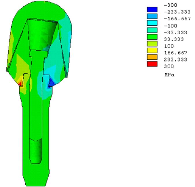
F. Felli et alii, Frattura ed Integrità Strutturale, 18 (2011) 14-22; DOI: 10.3221/IGF-ESIS.18.02

work the authors tried to replicate this loading condition to verify possible behaviour similarities between the retrieved
implants and the laboratory tested samples. After the experiments performed with the bore cylinder type, which
demonstrated a similarity of failure mode between retrieved and tested implants, another kind of dental prosthetic implant
has been tested. For these implants, more recent than the previous ones, there was no availability of implants broken "in
situ". Thus, a finite element analysis was required to assess the most stressed area of the implant under mastication-like
loading scheme. After fatigue testing, aim of this work was to verify whether fatigue failures occurred in the regions
suggested by FEA. Further studies on these implants concerned other aspects, involved in the component failure, such as
loosening of screws and flexural deformation.
This paper, for the first implant, aims at comparing service failure and simulated failure behaviour to build up a valid
testing method and to estimate the fatigue limit under which the implant could resist indefinitely. As far as the second
implant is concerned the aim of the work is to provide information on its fatigue behaviour in order to provide a possible
fatigue limit under loading conditions similar to those involved in the actual mastication.

MATERIALS AND METHODS

Implants

T       he tested implants belong to two different types:
        - Titanium (grade 2, according to the ASTM F-67 standards) hollow cylinder with holes on the side surface to
        promote osseointegration with the bone tissue (Bonefit hollow cylinder, ITI).
- Screw implant (Branemark system, Nobelbiocare) with threaded fixture in titanium (grade 2) with chemically etched and
anodic passivated surface; titanium abutment and connecting screw, Cr-Co alloy dental capsule with hemispherical profile,
coated with dental ceramic.
In Figs. 1 and 2 the two types of implants and their dimensions expressed in millimeters are reported.

                                                       Figure 1: Hollow cylinder type implant.

                                                             Figure 2: Screw type implant.

Mechanical stress
Implants are tested under fatigue loading in different ways. The first implant (hollow cylinder) is subjected to tensile stress
while the second one (screw type) is dynamically loaded with a complex stress system of compression-bending-torsion
loads similar to the one that takes place in the actual mastication action.

16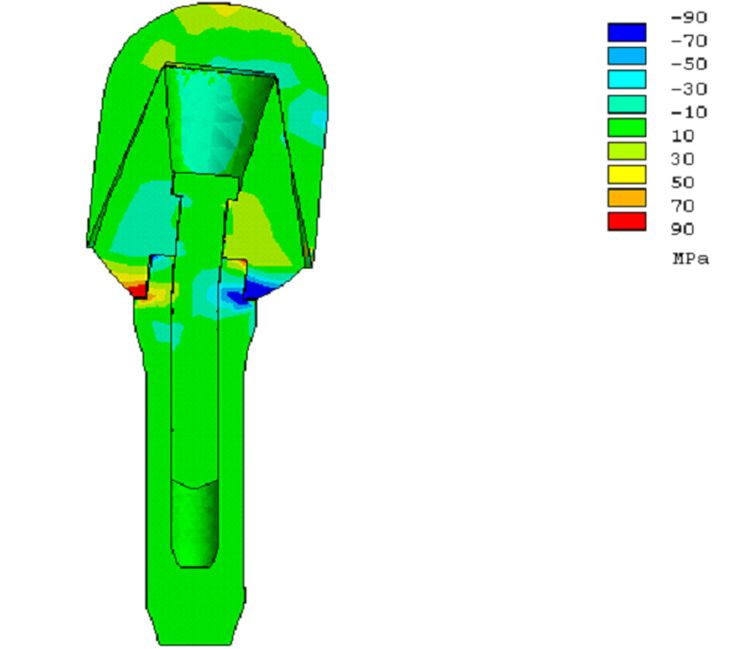
F. Felli et alii, Frattura ed Integrità Strutturale, 18 (2011) 14-22; DOI: 10.3221/IGF-ESIS.18.02
It is known that the load stress regime on the implant during service cannot be simply reduced to the elementary
compressive stress. Upon mandible closing, horizontal forces arise. These forces depend both on the dental cusps
profiles, differently inclined relatively to the occlusive force which is substantially vertical, and on the mastication motion
including side and protrusion movements of the mandible.
Moreover, the vector sum of vertical forces acting on a tooth is not directed along the longitudinal axis of the tooth itself,
thus bending moments arise. These bending moments added to those resulting from the horizontal forces, determine a
flexural stress which is not negligible. Since the horizontal force components generally do not lay on a plane formed by
their points of application and the symmetry axis of the implant (the tooth longitudinal axis) a torsion stress arises in
addition to existing compressive and flexural stresses.
In the cyclic fatigue regime, bending moments determine the necessary conditions for the initiation and subsequent
propagation of fatigue cracks in the portion of the tooth which is in tension.
Torsion moments, besides contributing to overall tension stress, can lead implant to mobilizing problems due to the
decrease of the screw clamping torque and shear actions on the fixture-bone interface.
Tests description
The fatigue tests performed on the two dental implants are executed using a hydraulic-drive fatigue test machine, while the
fracture surface analyses are carried out by a scanning electron microscope (SEM).
The first implant (hollow and bored cylinder) is incorporated in an aluminium cylinder for a depth corresponding to the
"implantantion-depth" (that is the same depth at which the implant should be inserted in the bone when in service) using
an epoxy resin. The aluminium cylinder allows the connection with the test machine grippers. The adhesion between
implant and cylinder is also increased by means of steel wires connected to the implant and immersed in the interface
epoxy resin which is, specifically, a double-component epoxy resin Mecaprex MA. Firstly, this implant system is tested in
air; three fatigue tests are performed using sinusoidal tension loads having increasing maximum values equal to 500, 750,
1000 N. The tests are repeated 3 times in order to achieve an acceptable statistical value considering the limited number of
samples available.
The selected maximum tension loads take into account the real average stress in the mastication which is, on the most
stressed teeth (molar and pre-molar), about 770 N. The minimum value of the sinusoidal load is fixed and constant for all
the performed tests and it is equal to 100 N. The loading frequency, fixed at 1 Hz, is comparable with the real average
mastication frequency. Then, other three tests are performed using the same set-up and loading system, but in a different
environment; the implant works in aqueous solution containing 3%wt NaCl in order to simulate, to a certain extent , the
corrosive environment established in the mouth during the mastication. The tension load is selected in order to simulate
the stress regime that occurs in the tension area of an implant when subjected to bending moments.
As far as the second type of implant (screw type) is concerned, the complex stress regime to which it is subjected is firstly
analysed by means of a finite elements solver provided by a software tool (ANSYS 7.0) for the Branemark type implant;
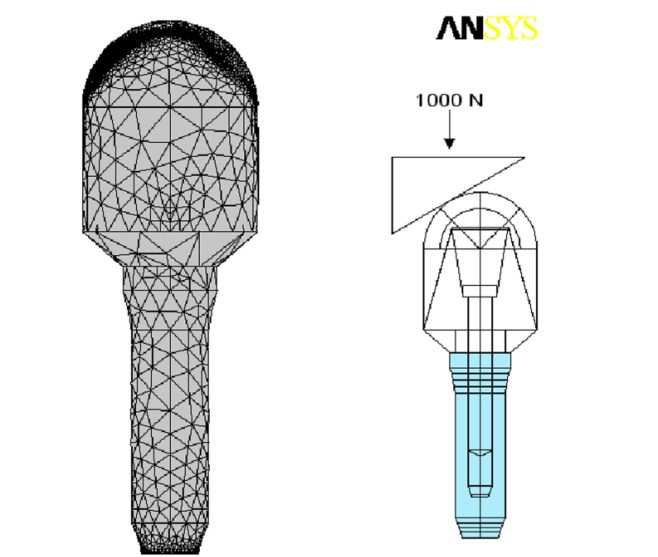
the loading scheme and the results are shown in Figs. 3, 4, and 5. In the left part of Fig. 3, the 3D-mesh used for the finite
elements calculation is shown. On the right part it is possible to observe the loading scheme with the punch having the
contact plane, transmitting the load, inclined of 30° on the horizontal, on which is applied a 1000 N force. The surface in
light blue is the part of the implant (fixture) that is constrained by the bone.
Figure 3: 3D mesh and loading scheme.
17F. Felli et alii, Frattura ed Integrità Strutturale, 18 (2011) 14-22; DOI: 10.3221/IGF-ESIS.18.02
Figure 4: Visualization of tensile stress along implant long Figure 5: Visualization of shear stress perpendicular to implant long
axis. axis.
The second implant is then tested against fatigue by means of the same test machine using a particular specimen-carrier
specifically designed for this implant and made with brass (UNI P-CuZn40Pb2 Brass type). In this specimen carrier a
round housing is drilled for the incorporation of the implant by means of a dental resin. The interface between implant
and specimen-carrier is established at two levels: the first resin layer abuts on the threaded fixture and it is constituted by
an acrylic thermosetting resin for dental uses (CEMEX), which has mechanical properties similar to the cortical bone
tissue. For the second layer, in contact with the specimen-carrier, a dental thermosetting epoxy resin (JET REPAIR) is
used to approximate the mechanical behavior of the inner sponge-like bone tissue. The implant on which a Cr-Co dental
alloy capsule having an hemispherical profile is mounted, is stressed by means of brass punches. These punches have
three different inclinations of the contact plane (the plane that transmits the force from the test machine to the implant):
0°, 15°, 30° relative to the horizontal.
The stress acting on the implant, with the 0° angled punch, is nominally only compressive while using the 15° angled
punch, and even more the 30° angled punch the bending and torsion stress components arise and become rather large.
The first set of tests, very similar to those performed by other researchers 24, consists in applying a vertical compressive
sinusoidal loading to the punch, with a frequency of 3 Hz and an amplitude of 700 N with a minimum value set to zero.
RESULTS AND DISCUSSION
C oncerning the first type of implant, the results of the above described tests together with a conventional static
tensile test are reported in two Wohler-type diagrams (maximum load - cycles to failure), one for each test
environment (Fig. 6).
By examining the figure it can be immediately noticed only a little difference in the resistance observed during air tests and
saline solution tests: this confirms the good behavior of titanium as implant material and shows a fatigue limit of about
500 N.
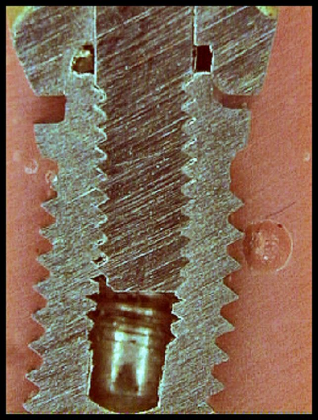
The macroscopic analysis shows the fatigue fracture initiation in near-bores regions, which are areas of maximum stress
intensification. Therefore the bores, although promote osseointegration act as stress intensifiers when the implant is in a
tensile stress condition due to bending moments acting on the implant .
SEM analyses show a typical fatigue fracture characterized by brittle type crack advancing (Figs. 7 and 8) with a
substantially transgranular damage propagation and with evident cleavage planes. On these cleavage planes, at higher
magnification, the typical fatigue striations are observed.
The results of the tests have been compared with a batch of cylinder implants which have broken in service. The fractures
occurred in normal use condition in a period ranging between eight months and ten years (Figs. 9 and 10). All these
hollow cylinder prostheses show a typical fragile transgranular failure morphology, with clear cleavage planes and fatigue
striations. This failure morphology, very similar to the one obtained in low frequency (1 Hz) laboratory tests in an
18F. Felli et alii, Frattura ed Integrità Strutturale, 18 (2011) 14-22; DOI: 10.3221/IGF-ESIS.18.02
aggressive environment, shows how the mastication motion has evident similarity with this kind of mechanical load
condition.
Figure 6: Wohler-type diagram for cylindrical implant.
Figure 7: Fracture surface of tested implant. Figure 8: Fracture surface of tested implant.
Figure 9: Fracture surface of implant failed in service. Figure 10: Fracture surface of implant failed in service.
19F. Felli et alii, Frattura ed Integrità Strutturale, 18 (2011) 14-22; DOI: 10.3221/IGF-ESIS.18.02
For the second implant type ( screw implant), the solution of the loading scheme is reported in Fig 4, showing the cross-
section view of the deformed implant and the tension/compression stress in the direction of the implant long axis
(symmetry axis). This image highlights that the most stressed areas, both in tension (red) and in compression (blue), are
the contact regions between the fixture and the stump. Upon breaking down this interface, there will occur a re-
distribution of the stresses and strains in which the maximum stress intensification will be on the connecting screw. The
connecting screw, before interface failure, is already subjected to a tension of about 100 MPa both in tension and
compression. This stress intensification, in the portion of the implant subjected to tensile stress, may easily lead to crack
initiatiation when the applied load becomes cyclic and high enough.
Fig. 5 shows the deformed implant and the stresses in the direction perpendicular to the implant long axis, torsion
moments and shear stresses in the horizontal plane, due to horizontal forces. Shear stresses reach the maximum value on
the contact surfaces between the fixture and the stump causing the implant to be mobilized and subjected to partial
rotation around his long axis. These shear actions can loosen the screw and act on the implant-bone tissue interface to
rotate the whole implant.
The first fatigue test carried out on this implant with the flat punch (0° angled), extended for 250000 cycles does not lead
to any damage and mobilizing effect on the implant. The other two tests, performed with inclined punches, showed a
mobilizing effect after the same number of cycles (250000). By using the 15° angled punch this mobilizing appears to be
slight and caused by the screw-fixture clamping torque decrease. With the 30° angled punch, the axial deformation due to
the bending moment is evident (Fig. 11) and mobilizing phenomena due to the torsion moment are still noticeable and
similar to the previous case.
Figure 11: Screw implant, deformed after the test.
The other six tests are performed using the most severe loading scheme (30° angled punch) and sinusoidal stress
maximum values growing over the range 700 N - 3500 N, with minimum load set to zero. The maximum value (3500 N)
represents the stress at which the implant fails under static load, as in common tensile test (it would be the static
resistance of the implant). The test results are summarized in Wohler-like plot, reported in Fig. 12 and relative to this
implant.
From the diagram analysis it can be noticed the existence of a fatigue limit at about 600-700 N. The fracture analysis
showed that the damage has firstly affected the connecting screw, thus the fracture itself is promoted by a decrease in the
clamping torque of the screw and by the subsequent deformation of the hexagonal head. Then the crack triggers and
starts advancing in the proximity of the threads corresponding to the first section immersed in the bone (in the resin in
20F. Felli et alii, Frattura ed Integrità Strutturale, 18 (2011) 14-22; DOI: 10.3221/IGF-ESIS.18.02
our tests). The failure of the screw causes the implant fixture to be subsequently broken due to the reduction of the
resisting cross section.
The SEM image (Fig. 13) shows the crack initiation site, the propagation area and the final rupture region.
Figure 12: Wohler diagram for screw type implant.
Figure 13: Wide angle SEM image of the fracture surface of the screw implant.
CONCLUSIONS
T wo dental implants are tested against fatigue by using different loading schemes. For the first implant (hollow
cylinder with bored side surface) is selected a tensile cyclic stressing so that it is possible to simulate the tension
stress, which actually occurs during mastication motion in a portion of the implant. The second implant is fatigue
tested using a mixed loading scheme comprising all the mechanical stresses that can act on an implant during its service
life. This composite load is constituted by compression/tension, bending, and torsion components. The performed tests
are summarized in the Wohler-type diagrams that exhibit the static resistance, which can be assumed as the strength of the
whole implant, and a fatigue limit, that is the load below which the implant could resist indefinitely or the limit load at
which no damage can start.
Moreover, the analysis on the hollow cylinder implant has provided other results:
- the difference in air and saline solution tests is small. This can confirm the effectiveness of the titanium for the
production of such implants.
21F. Felli et alii, Frattura ed Integrità Strutturale, 18 (2011) 14-22; DOI: 10.3221/IGF-ESIS.18.02
- the fracture surface morphology of the specimens broken in our test is very similar to the fracture surface of the
implants broken in service. It means that the tensile stress occurring in service life is the main reason of the fatigue failure
of these implants. The crack initiate near the holes and then propagates through the section of the implant. So the holes
on the side surface while promoting osseointegration, are adverse for mechanical strength.
The analysis performed on the second implant (the screw type) leads to the following results:
- the fatigue tests displayed a fatigue limit of about 600-700 N. This range is high enough to consider valid this kind of
implant; the limit is roughly comparable with the actual average stress on most stressed tooth but the implant, in the tests,
was not inserted in a dental arch and then it has to bear the whole load applied.
- The finite element analysis shows that the most stressed areas are the ones on which the crack actually initiates and
propagates. The stress values from the FE analysis are in a good agreement with the static values measured for this
implant.
REFERENCES
[1] P. I. Branemark, B. O. Hansson, R. Adell, U. Breine, J. Lindstrom, O. Hallen, A. Ohman, Scand. J. Plast. Reconstr.
Surg., 3(2) (1969) 8.
[2] L. Carlsson, T. Rostlund, B. Albrektsson, T. Albrektsson, P. I. Branemark, Acta Orthop. Scand., 57 (1986) 2885.
[3] H. A. Luckey, F. Kubli, ASTM Special Techn. Publs., 796 (1983).
[4] D. F. Williams, Titanium and titanium alloys. Fundamental aspects of biocompatibility. Boca Raton FL: CRC Press
(1981).
[5] B. Rangert, T. Jemt, L. Jorneus, Int. J. Oral Maxillofac. Implants, 4 (1989) 241.
[6] A. Wennenberg, T. Alberktsson, B. Andersson, J. J.Krol, Clin. Oral Implants Res., 6 (1995) 24.
[7] Y.S. Al Jabbari, R. Fournelle, G. Ziebert, J. Toth, A. M. Iacopino, Journal of Prosthodontics, 17 (3) (2008) 168.
[8] W. Slot, G. M. Raghoebar, A. Vissink, J. J. Huddleston Slater, H. J. A. Meijer, Journal of Clinical Periodontology, 37
(1) (2010) 98.
[9] A. Behneke, N. Behneke, B. D'hoedt, W. Wagner, Int. J. Oral Maxillofac. Implants, 12 (1997) 749.
[10] B. Friberg, H. Nilson, M. Olsson, C. Palmquist, Clin. Oral Implants Res., 8 (1997) 279.
[11] R. Leimola-Virtanen, J. Peltola, E. Oksala, H. Helenius, R.P. Happonen, Int. J. Oral Maxillofac. Implants, 10 (1995)
373.
[12] D. Buser, R. Merickse-Stern, J.P. Bernard, A. Behneke, N. Behneke, H.P. Hirt, U.C. Belser, N.P. Lang, Clin. Oral
Implants, 8 (1997) 161.
[13] C. J. Goodacre, J. Y. Kan, K. Runcgharassaeng, J. Prosthet. Dent., 81 (1999) 537.
[14] F. M. Saliba, M. Cardoso, M. F. Torres, A. C. Teixeira, E. J. V. Lourenço, D. T. De Moraes, Journal of Applied Oral
Science, 19 (1) (2011) 63.
[15] D. H. Kohn, J. Oral Implantol., 11 (1992) 391.
[16] R. Bedini, G. De Angelis, G. Di Cintio, R. Ielapi, M. Tallarico, U. Romeo, Evaluation of surface treatment on
mechanical fatigue performance of titanium plasma-sprayed and sandblasted large-grid and acid-etched titanium
dental implants. Rapporti ITISAN (2001).
[17] R. Bedini, G. De Angelis, A. Fasano, R. Ielapi, M. Tallarico, L. Pacifici, Mechanical fatigue performance of an
experimental dental implant. Rapporti ITISAN (2001).
[18] P. I. Branemark, G. A. Zarb, T. Alberktsoon, Tissue-integrated prostheses, osseointegration in clinical dentistry.
Chicago Quintessence Publshing Co. Inc. (1985).
[19] L. Carlsson, T. Haraldson, In: T. Tissue-integrated prostheses, Eds: P. I. Branemark, G. A. Zarb GA, T. Alberktsoon,
Chicago Quintessence Publshing Co. Inc., (1986) 153.
[20] M.Weinlander, Dent. Clin. North. Amer., 35 (1991) 585.
[21] A. Schroeder, O. Pohler, F. Sutter, SSO Schweiz Monatsschr Zahnheilkd, 86(7) (1976) 713.
[22] D. Buser, R. K. Schenk, S. Steinemann, J. P. Fiorellini, C. H. Fox, H. Stich, J. Biomedic Mater. Res., 25 (1991) 889.
[23] K. A. Thomas, S. Cook, J. Biomed. Mater. Res., 19 (1985) 875.
[24] ISO SC 8 WG 3 Working Draft - CEN/TC 55 Dentistry. Dental Implants - Dynamic continuous fatigue test.
Geneva: International Organization for Standardization (1994).
22You can also read