MITUS Minimally Invasive Technique for LINK Unicondylar Sled Prosthesis - | Surgical Technique - Link Nederland
←
→
Page content transcription
If your browser does not render page correctly, please read the page content below
MITUS®
Minimally Invasive Technique for
LINK® Unicondylar Sled Prosthesis

                             | Surgical Technique
Presented by:

Waldemar Link GmbH & Co. KG
Barkhausenweg 10 · 22339 Hamburg, Germany
P.O. Box 63 05 52 · 22315 Hamburg, Germany
Tel.: +49 40 53995-0 · Fax: +49 40 538 6929
E-mail: info@linkhh.de · www.linkorthopaedics.com
Contents

MITUS®
Minimally Invasive Technique for
LINK® Unicondylar Sled Prosthesis

		   System Description
02   LINK® Unicondylar Sled Prosthesis
03   Femoral Components and Tibial Plateaus
03   LINK PorEx® Surface Modification (TiNbN =Titan-Niob-Nitrid)
04   Minimally Invasive Surgical Technique,   Rünow

05   Indications / Contraindications
06   Case History
07   Literature

		   Surgical Technique
08   Patient Positioning
10   Tibial Resection
17   Femur Resection
19   Trial Reduction
23   Cementation

		   Instruments
25   MITUS® Instrument Set of Minimally Invasive Surgical Technique
     for LINK® Unicondylar Sled Prosthesis

26   Accessories: X-ray Templates, further Information

		   Important Information regarding the use of our implants

                                                                                 01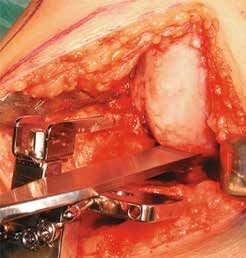
System Description

        LINK® Unicondylar Sled Prosthesis

     The successful design of LINK‘s Unicondylar Sled Prosthesis which was originated in 1969 has remained
     unchanged since its last modification in 1981. This extraordinary time period and the outstanding long-term
     clinical results have been reported in a number of publications *.

     Further advantages:
     • high joint mobility
     • short recovery period

     The design of the femoral component preserves bone substance and permits femoral resurfacing.
     This treatment is therefore available as a fall-back option.

     The instruments and the surgical technique are regularly optimised to ensure ease of use and reliable
     implantation.

     The LINK® Unicondylar Sled Prosthesis is available in four sizes.

     * Exemplary: Annual Report, The Swedish Knee Arthroplasty Register, www.knee.nko.se

02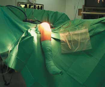
System Description

Femoral Components
The large radii of the femoral surface distributing
the contact stress more homogenously. The glo-
bular structure of the concave inner surface of the
sled provides optimal bonding between implant and
cement. The design incorporates two posts whose
shape and alignment aid in positioning the sled. The
implant is easy to remove should revision become
necessary.

Tibial Plateaus
The tibial plateaus can be used medially as well
as laterally owing to their symmetrical shape. The
sizing is adapted to the anatomical shape of the
head of the tibia. Two designs are available:

• Type all-polyethylene (non metal-backed)
  This design is available in four heights and four
  diameters. The structured underside allows a very
  good interface between implant and bone cement.

• Type metal-backed
  In this design, the tibial plateaus are available in
  three heights and three diameters. The globular
  structure on the underside of the plateau offers
  optimum bonding between the implant and bone
  cement.

LINK PorEx® (TiNbN = Titan-Niob-Nitrid)
Surface modification
The hypoallergenic LINK PorEx® surface modification
leads to a ceramic-like surface, which significantly
reduces the release of ions and can improve tole-
rance in patients who are sensitive to metal 1).

This surface is extremely hard and possesses abra-
sion properties similar to those of ceramics. These
qualities and the wetting angle of the surface give it
a low friction coefficient when in contact with fluids 1).

1)
     Study of the influence of TiNbN-coating on the ion release of
     CoCrMo-alloys in SBF buffer simulator testing.

                                                                     03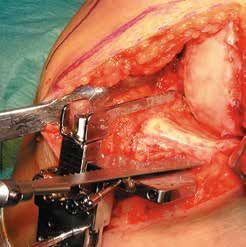
System Description

         Rünow Minimally Invasive Surgical Technique
     For implantation of a sled prostheses it is essential to select the correct
     indication. The concept is based on the fact that in early stages of knee
     osteoarthritis (OA) the cartilage damage is limited to a single compart-
     ment within the knee joint.

     The design of the LINK® Unicondylar Sled Prosthesis ensures that
     only minimal bone resection is required when preparing the bone to
     receive the femoral and tibial components. This preserves high-quality
     bone, particularly the hard sub-chondral bone, which is important for
     secure long-term fixation of the implant.

     The Tibial Saw Guide supports resection according to anatomical
     conditions and ensures precise, reproducible bone cuts.

     The MITUS® Instrument Set offers distinct advantages to the surgeon:

     • minimal bone resection
     • full control over the level of tibial resection
     • opportunity to try out different sizes using trial implants
     • option to perform the surgery using either conventional or
       minimally invasive surgical techniques
     • medial or lateral use of instruments possible

     Two different forms of surgical approach can be used

     Conventional Approach: through a midline or a medial parapatellar
     skin incision. The joint cavity is reached via a medial parapatellar
     incision and splitting of the quadriceps tendon. The patella is
     everted laterally.

     Minimally Invasive Approach: through a short parapatellar skin
     incision. The capsular incision is also parapatellar allowing access
     to the joint with minimal disturbance of the extensor mechanism
     and without dislocating the patella.

     The minimally invasive technique reduces complications and can
     be performed with great precision provided the LINK® instruments
     are used correctly.

04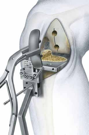
Indications/Contraindications

   Specified Indications and Contraindications

                                                                                          additional with
  Product: LINK® Unicondylar Sled Prosthesis                    LINK® Sled Prosthesis      PorEx® (TiNbN)
                                                                                        Surface Modification

General Indications
• Severe joint diseases with limitation of mobility due to
  degenerative, rheumatoid or post-traumatic arthrosis or
                                                                          X                      X
  arthritis. Joint fractures which disallow an osteosynthetic
  reconstruction.

Indications
• Unicondylar arthrosis by intact ligaments including both
                                                                          X                      X
  cruciate ligaments.
Differential Indications
• Valgus/Varus deformities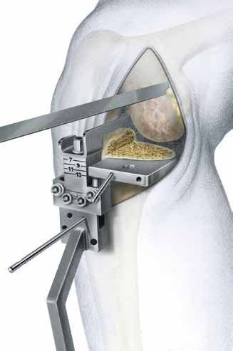
Case History

          Case Studies

     1a                                   1b                                    1c
     Male, age 75 years

     Fig. 1a: Medial compartment OA, Ahlbäck Grade II, with pain after 15 minutes walking.

     Fig. 1b,1c: Following minimally invasive technique of an LINK® Sled Prosthesis, postoperative X-rays
     show horizontal positioning of the Tibial Plateau in the coronal plane (Fig. 1b), a slight posterior slope
     of the plateau in the sagittal plane (Fig. 1c). RSA beads are issued in bone and implants. Two days after
     surgery, the patient was able to walk with crutches. His active ROM was 5 - 120°. At one week, he walked
     without crutches; at six weeks, he walked 5 km without any pain, and had ROM of 0 - 130°.

     2a                                           2b

     Female, age 62 years

     Fig. 2a: Medial compartment OA, Ahlbäck Grade II, unable to walk without crutches, walking distance 500m.

     Fig. 2b: Following minimally invasive technique of a LINK® Sled Prosthesis, good alignment and horizontal
     positioning of the Tibial Plateau was achieved. At four postoperative days, her ROM was 0 - 95°. By the end
     of the first month, the ROM was 0 - 115°.

06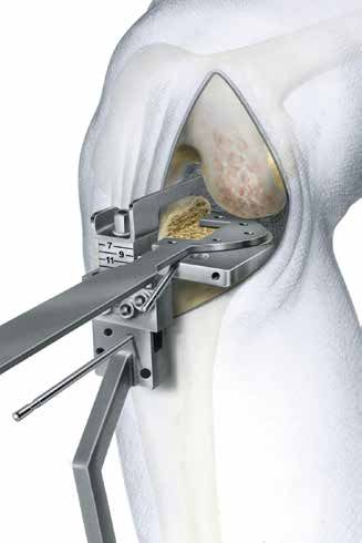
Literature

J. Dreyer, H. J. Späh, A. Teichner                                       T. Ashraf, C. E. Ackroyd, J. H. Newman, R. Evans
Längerfristige Erfahrungen mit Schlittenendoprothesen St. Georg®         Lateral unicompartmental knee replacement – survivorship and cli-
Zeitschrift für Orthopädie u. I. Grenzgebiete,1984; 122:71-77 (K11)      nical experience over 21 years; JBJS, 2002, 84-B: 1126-30 (K81)

N. J. Olsen, R. Ejsted, P. Krogh                                         C.E. Ackroyd
St. Georg® Modular Knee Prosthesis. A two-and-a-half to six-year         Medical Compartment Arthroplasty of The Knee; JBJS (Br), 2003,
follow-up; JBJS, 1986; 68-B: (K18)                                       83-B: 919-922 (K 83)

K. Heinert, E. Engelbrecht                                               R.E. Gleeson, R. Evans, C.E. Ackroyd, J. Webb, J.H. Newman
Total Knee Replacement, Ten-Year Follow-up Results of St. Georg®         „Fixed or mobile bearing unicompartmental knee replacement? A
Knee Prosthesis Systems, 2400 Sledges and Hinges. Proceeding of          comparative cohort study“; The Knee 11, Issue 5, October 2004,
the International Symposium on Total Knee Replacement; Springer          pages 379-384 (K 90)
Verlag: Tokyo, Heidelberg, New York (1987); 111-122
                                                                         R.G. Steele, S. Hutabarat, R.L. Evans, C.E. Ackroyd and, J.H. Newmann,
E. Nieder, E. Engelbrecht, A. Keller                                     „Survivorship of medial St. Georg Sled Unicompartmental Knee Re-
Totale intrakondyläre Scharniergelenksendoprothese mit Rotations-        placement during and beyond the second decade“; JBJS (Br), 2006,
möglichkeit Endo-Modell®; Orthopädische Praxis, 1987; 5; 402-412 (K34)   88-B: 1164-1168 (K 88)

K. Heinert, E. Engelbrecht                                               T.M. Bakhsh et al.
Langzeitvergleich der Knie-Endoprothesensysteme St. Georg®               „Results of unicompartmental knee replacement“; Saudi Med J 2007,
10-Jahres-Überlebensraten von 2236 Schlitten- und Scharnier-             Vol. 28(7): 477-480 (K 103)
Endoprothesen; Der Chirurg 1988; 59:755-762 (K38)
                                                                         J. Newman, R.V. Pydisetty, C. Ackroyd
J. Mackinnon, S. Young, R. A. J. Baily                                   „Unicompartmental or total knee replacement – The 15-year results
The St. Georg® Sledge for Unicompartmental Replacement of the Knee,      of a prospective randomised controlled trial“; JBJS (Br), 2009, Vol.
a prospective study of 115 cases; JBJS, 1988; 70-B:217-222 (K37)         91-B: 52-57 (K 95)

I. Stockley et al.
Bicondylar St. Georg® Sledge Knee Arthroplasty; Clinical Orthopae-
dics and Related Research, 1990; 255:228-234 (K47)

E. Nieder
Schlittenprothese, Rotationsknie und Scharnierprothese Modell St.
Georg® und Endo-Modell®, Differentialtherapie in der primären Knie-
gelenkalloarthroplastik; Orthopäde (1991) 20:170-180 (K45)

T. Gabrielidis, A. Eghbal
Mittelfristige Ergebnisse nach Implantationen von Schlittenprothesen
des Typs St. Georg® bei medialer Gonarthrose; Orthop. Praxis, 1992;
28-5:361-364 (K44)

S. Ansari, J. H. Newman, C. E. Ackroyd
St. Georg® sledge for medial compartment knee replacement 461
arthroplasties followed for 4 (1-17) years; Acta Orthopedica Scandi-
navica 1997; 68-5:430-434 (K58)

F. Alt, U. Sonnekalb, N. Walker
Unikondyläre Schlittenprothesen versus scharniergeführte Totalen-
doprothesen des Kniegelenkes; Orthop. Praxis 1998; 1:20-24 (K61)

J. H. Newman, C. E. Ackroyd, N. A. Shah
Unicompartmental or total knee replacement. Five-year results of a
prospective, randomized trial of 102 osteoarthritic knees with uni-
compartmental arthritis; JBJS, 1998; 80-B:996-1000 (K62)

A. E. Weale, D. W. Murray, J. H. Newman, C. E. Ackroyd
The length of the patellar tendon after unicompartmental and total
knee replacement; JBJS, 1999; 81-B:790-795 (K69)

A. E. Weale, D. W. Murray, J. Baines, J. H. Newman
Radiological changes five years after unicompartmental knee replace-
ment; JBJS, 2000; 82-B:996-1000 (K73)

O. Robertsson, K. Knutson, S. Lewold, L. Lidgren
The Swedish Knee Arthroplasty Register Outcome with special em-
phasis on 1988-1997; Handout Scientific Exhibition AAOS San Fran-
cisco 2001(The Swedish Knee Arthroplasty Register 2001) (K77)

LINK® NEWS 12 – Orthopädie Aktuell
MITUS™ Minimal Invasive Technik für Unikondyläre Schlitten Endo-
Modell® nach Rünow – schont Weichteile; Februar 2002, Waldemar
Link GmbH & Co. KG, Hamburg (K79)

C. E. Ackroyd, S. L. Whitehouse, J. H. Newman, C. C. Joslin
A comparative study of the medial St. Georg® Sled and Kinematic
total knee arthroplasties – ten year survivorship; JBJS, 2002, 84-B:
667-672 pp. (K80)

                                                                                                                                                  07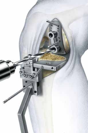
Surgical Technique

     Patient Positioning

                           The limb is placed in a thigh support with
                           45° flexion of the hip. The leg is hanging
                           down. It should be possible to flex the
                           knee at least 120°. When using a medial
                           incision a lateral thigh support is needed.

                           The operation is performed with the surgeon
                           sitting in front of the flexed knee. The other
                           leg is placed in a leg support leaving plenty
                           of space for the surgeon and the assistant.
                           The operation is performed in a bloodless
                           field.

08
Surgical Technique
Patient Positioning
With the knee flexed 90°, a medial parapatellar incision is made starting at the margin of the vastus
medialis 2–3 cm medial to the patella and extending distally and diagonally to the tibial tuberosity.
A medial parapatellar capsule incision is made. For better visualisation the incision is angulated in its
proximal part. The vastus medialis is detached. The capsule is released from the tibia almost to the front
of the medial collateral ligament. The meniscus is removed. Partial excision of the retropatellar fat pad is
necessary to gain better exposure of the intercondylar notch.
A retractor is placed in the lateral recess, allowing inspection of this compartment. To examine the
patellar articulation, the knee is extended. If there are any doubts preoperatively about the condition of
the other compartments diagnostic arthroscopy or MRI can be performed prior to the operation. After
inspection, the retractor is placed in the intercondylar notch and the curved retractor behind the femoral
condyle, to get a full view of the medial compartment.
09Surgical Technique
Tibial Resection
The purpose of the LINK® Unicondylar Sled Prosthesis is to restore the damaged joint surfaces and the
mechanical axis; a slight under-correction is desirable.
The Tibial Saw Guide allows the surgeon to determine and achieve the desired cutting depth precisely
and to control the cutting in the frontal and the sagittal planes. The Saw Guide can be used with either
a minimally invasive technique or the traditional exposure.
10Surgical Technique
Tibia Resection
Grade I
Grade II
Grade III
In knee replacement surgery by the traditional technique, the deepest point and the most damaged area
of the tibial plateau are taken as the basis for determining the depth of the tibial resection. The depth of the
resection is then highly dependent on the surgeon‘s experience. Often further resection is needed or the
height of the Tibial Plateau must be changed to obtain the desired alignment and stability of the knee. The
best aid to determining the depth of the horizontal cut is weight-bearing radiographs of the knee and pre-
operative observations of the degree of cartilage damage. These allow a slight undercorrection of only a
few degrees of varus to be achieved. The analysis of the weight-bearing radiographs is based on the
classification of Ahlbäck.
The proposed resection depths are based on the use of a 9-mm high Tibial Plateau.
Grade I The joint space is reduced by one-half. The cartilage of the tibial condyle is preserved but reduced
in height. The Cutting Platform should be adjusted to 11 mm depth. The stylus is placed at the deepest point
of the remaining cartilage of the tibial condyle.
Grade II Total loss of the cartilage on both the femoral and the tibial condyles.The Cutting Platform should
be adjusted to 9 mm depth and the stylus placed at the deepest point of the exposed bone of the tibial
condyle.
Grade III Half a centimeter bone attrition of the femoral and tibial condyles on the frontal view weightbearing
radiograph. The Cutting Platform should be adjusted to 7 mm and the stylus placed at the border between
the exposed and the eroded bone.
The stylus is not placed at the level of the planned surface of the Tibial Plateau. In Grade I the surface of
the Tibial Plateau will be lower than the surface of the tibial condyle, and correspondingly in Grade III the
surface of the Tibial Plateau will be higher than the surface of the damaged tibial condyle.
11Surgical Technique
Tibial Resection
Resection Height
Height of
Grade I Grade II Grade III
Tibial Plateaus
7 mm 9 7 –
9 mm 11 9 8
11 mm 13 11 9
Table 1:
Depth of the tibial resection (mm) in relation to the chosen height
of the Tibial Plateau.
Height of Tibial Plateaus
Resection
Grade I Grade II Grade III
Height
7 mm – 7 9
9 mm 7 9 11
11 mm 9 11 13
Table 2:
Height of the Tibial Plateau (mm) in relation to the depth of the
tibial cutting.
Table 1
When a 7-mm high Tibial Plateau is used, the tibial resection depth should be 9 mm in Grade I knees and
7 mm in Grade II knees. Because the construction of the Tibial Saw Guide does not permit less than 7 mm
resection depth between the tip of the stylus and the Cutting Platform a 7-mm Tibial Plateau cannot be used
in Grade III osteoarthrosis, and such knees must therefore be undercorrected. According to suggestions given
above, the depth of the resection when using an 11-mm Tibial Plateau will be 13 mm in Grade I, 11 mm in
Grade II, and 9 mm in Grade III. These resection depths will unnecessarily be too deep and will remove more
bone than necessary.
Table 2
It is convenient to use the same resection depth independent of the degree of cartilage and bone damage.
This means that a resection depth of 9 mm in relation to the tibial surface is needed in order to use a 7-mm
Tibial Plateau in Grade I, a 9-mm Tibial Plateau in Grade II and an 11-mm Tibial Plateau in Grade III to achieve
the same degree of alignment.
12Surgical Technique
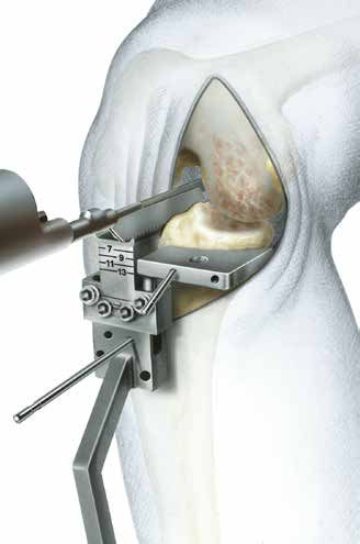
Tibial Resection
B
A
The clamp of the Tibial Saw Guide is placed at the level of the ankle directly proximal to the malleoli.
The posterior slope of the Tibial Component
Note that the Cutting Platform has a posterior slope of 6° in relation to the long axis of the Guide. The
Tibial Saw Guide should be adjusted in the vertical plane parallel to the long axis of tibia by moving the
vertical rod ventrally. In most cases the Guide needs to be moved 20–25 mm anteriorly to obtain the
required posterior angle of a 6°. Lock Screw A.
The horizontal slope of the Tibial Component
The horizontal slope of the Tibial Component can be adjusted by placing the distal fixation of the long
rod beneath the actual tibia condyle. In women the rod is moved approximately 20–25 mm and in men
25–30 mm from the centre to achieve a cutting surface perpendicular to the long axis of tibia. The hori-
zontal slope is controlled with the Alignment Rod. Lock Screw B.
13Surgical Technique
Tibial Resection
E
P
A
B
The Eminentia Saw Guide (E) is placed close and parallel to the eminentia along the planned sagittal cut.
There are Cutting Platforms (P) for the medial as well as the lateral compartments. The cutting depth
can be set between 7 and 13 mm by using a Screwdriver in the adjustment Hole (B). The Cutting
Platform is secured and locked with Screw (A).
The Tibial Saw Guide is fixed with a Fixation Pin in the central hole of the platform. The Pin is angulated
centrally towards the eminentia. A second Fixation Pin is placed in the Tibial Saw Guide to secure the
position.
14Surgical Technique
Tibial Resection
Bone Cuts
The vertical cut is performed along the Eminentia Saw Guide. The horizontal cut is guided by the
Cutting Platform.
The resected Tibial Plateau and remaining parts of the meniscus are then removed.
15Surgical Technique
Tibial Resection
Templates for Tibial Plateaus all-Poly-
ethylene (3 sizes: 45, 50, 55 mm)
Templates for Tibial Plateaus metal-
backed (3 sizes: 45, 50, 55 mm)
Depending on implant selection a Template is used for the sizing of the Tibial Plateau. Both are available
in three sizes (45, 50 and 55 mm).
The size of the Tibial Plateau in the sagittal plane is determined by placing the hook of the Template
behind the tibial condyle. If the anterior part of the Template is in alignment with the anterior border of
the tibia, that is the right size.
The size must be checked medially to ensure there is no medial overhang.
16Surgical Technique
Femur Resection
Do not remove the Tibial Saw Guide during the preparation for the Femoral Component.
Begin the preparation of the femoral condyle by cutting 3–5 mm of its posterior aspect to remove
undamaged cartilage.
Resect central and medial osteophytes, with attention to osteophytes behind the medial collateral
ligament.
17Surgical Technique
Femur Resection
There are four sizes of the Femoral Components (40, 46, 52 and 60 mm) and corresponding Drill Guides to
determine the correct size. The selected femoral Drill Guide is placed centrally on the femoral condyle and
fixed with two short Fixation Pins.
18Surgical Technique
Trial Reduction
Drill the anchoring holes. If it is difficult to drill the lower hole at 100-110° of flexion of the knee, the
Femoral Drill Guide is either too large or has been placed too far dorsally. Either change its position
or chose a smaller Drill Guide.
Mark the borders of the Drill Guide. Remove any cartilage inside the area marked for the Femoral
Component.
19Surgical Technique
Trial Reduction
Corresponding to the Femoral Drill Guides are four Femoral Trial Sled Prostheses. Before trialing the
chosen size, use a chisel or a saw to prepare a groove between the two anchoring holes. Place the
Femoral Trial Sled Prosthesis using the Inserting Forceps.
Test knee flexion and extension to make certain that the Femoral Trial Sled Prosthesis does not make
contact with the patella at any point during the movement. If it does, remove that part of the patella
that made the contact.
20Surgical Technique
Trial Reduction
The Tibial Plateaus (all-polyethylene) are available in 4 heights (7, 9, 11 and 13 mm) and the Tibial Plateaus
(metal-backed) in 3 heights (9, 11 and 13 mm).
With the Femoral Trial Sled Prosthesis in place, a 9-mm Tibial Trial Plateau is positioned. This is easiest
when the knee is flexed at least 90°. Some valgus load may be needed. If the Tibial Component has a
tendency to tilt anteriorly, the posterior angle of slope is too small. This can be corrected with a rasp.
Extend the knee to test the stability. In a normal knee there should be only a few millimeters’ space bet-
ween the components under valgus stress in a neutral position. If the gap is too wide change to a higher
Tibial Component. In genu recurvatum, the gap is wider in the neutral position and the knee is stable only
in hyperextension. Try to obtain the same degree of hyperextension of the knee as was present preopera-
tively, otherwise there is a risk that the knee will be overcorrected in valgus.
21Surgical Technique
Trial Reduction
A
B
If the knee is too tight, remove the Tibial Trial Component and the Fixation Pin in the Cutting Platform
and loosen Screw (A). Deepen the resection by lowering the platform to the appropriate level by turning
Screw (B) using a Screwdriver. As a rule 1-mm increase in resection depth increases varus angulation
by 2 degrees.
Secure the Cutting Platform by tightening Screw (A) and stabilize it with a Fixation Pin through one of
the unused holes in the Cutting Platform.
Perform the cut and repeat the trial by using the same height of the Tibial Trial Component.
22Surgical Technique
Cementation
Prepare the space for the keel of the Tibial Plateau (metal-backed), place the head of the Cancellous
Bone Compressor into the recess of the tibial Template and impact it using the Impactor.
The keel of the Tibial Plateau (all-polyethylene) is larger. To prevent fractures of the tibial condyle remove
some bone with a chisel before impacting the Bone Compressor.
Whichever Tibial Plateau is being used, the tibial surface needs to be protected during the compression
of the bone with the tibial Template, which is laid on the sawing platform. Test that the final choice of Tibial
Plateau fits and can be placed easily. Some valgus stress will be needed. The keel slot may be extended
anteriorly if necessary.
23Surgical Technique
Cementation
Before cementing the prosthesis remove the Tibial Saw Guide.Using an appropriate cementing technique,
cement the Femoral Prosthesis first. Remove excess cement with the curette.
Extend the knee to a neutral position and allow the cement to harden. Remove any remaining excess
cement.
Release the tourniquet and carry out careful hemostasis. The capsule and skin are sutured with the knee
flexed at 90°.
24Instruments
MITUS® Instrument Set
for Minimally Invasive OP-Technique of the LINK® Unicondylar Sled Prosthesis
Container 2
Container 1
Item no. Instrument Set, complete (Container 1 and 2)
Set complete, in 2 standard containers, on 3 trays with storage inserts
15-2201/01
Consisting of:
05-2001/03 N11 Standard Container, empty, 575 x 275 x 100 mm 1 ea.
05-2002/03 N21 Standard Container, empty, 575 x 275 x 130 mm 1 ea.
Lower Tray (Container 1), empty,
15-2200/02
stainless steel, 550 x 265 x 50 mm 1 ea.
Upper tray (Container 1), empty,
15-2200/03
stainless steel, 550 x 265 x 50 mm 1 ea.
Tray (Container 2), empty,
15-2200/01
stainless steel, 550 x 265 x 50 mm 1 ea.
25Accessories
X-rays
X-ray Templates, 110% actual size, 1 sheet
Item no. Application
15-2021/10 for Unicondylar LINK® Sled Prosthesis
15-2020/40 to 15-2020/60
15-2021/11 for Tibial Plateaus (metal-backed)
15-2030/01 to 15-2030/12
15-2021/13 for Tibial Plateaus (all-polyethylene)
15-2028/01 to 15-2028/12
Further Information
Catalogue:
LINK® Unicondylar Sled Prosthesis
with MITUS® Instruments
Implants & Instuments
available on request.
26Notes
27Notes 28
Important Information

Please note the following regarding the use of our implants:

1. Choosing the right implant is very important.
   The size and shape of the human bone determine the size and shape of the implant and also limit the load
   capacity. Implants are not designed to withstand unlimited physical stress. Demands should not exceed
   normal functional loads.

2. Correct handling of the implant is very important.
   Under no circumstances should the shape of a finished implant be altered, as this shortens its life span.
   Our implants must not be combined with implants from other manufacturers.

   The instruments indicated in the Surgical Technique must be used to ensure safe implantation of the components.

3. Implants must not be reused.
   Implants are supplied sterile and are intended for single use only. Used implants must not be reused.

4. After-treatment is also very important.
   The patient must be informed of the limitations of the implant. The load capacity of an implant cannot compare
   with that of healthy bone!

5. Unless otherwise indicated, implants are supplied in sterile packaging.
   Note the following conditions for storage of packaged implants:
• Avoid extreme or sudden changes in temperature.
• Sterile implants in their original, intact protective packaging may be stored in permanent buildings up until the
   “Use by” date indicated on the packaging.
• They must not be exposed to frost, dampness or direct sunlight, or mechanical damage.
• Implants may be stored in their original packaging for up to 5 years after the date of manufacture. The “Use by”
   date is indicated on the product label.
• Do not use an implant if the packaging is damaged.

6. Traceability is important.
   Please use the documentation stickers provided to ensure traceability.

7. Further information on the material composition is available on request from the manufacturer.

Follow the instructions for use!

Waldemar Link GmbH & Co. KG, Hamburg

All content in this catalog, including text, pictures and data, is protected by law. Every instance of use, whether in part or
in whole and which is not permitted by law, is subject to our prior consent. In particular, this applies to the reproduction,
editing, translation, publishing, saving, processing, or passing on of content stored in databases or other electronic media
and systems, in any manner or form. The information in the catalogs is solely intended to describe the products and does
not constitute a guarantee.

The Surgical Technique described has been written to the best of our knowledge and belief, but it does not relieve the
surgeon of his/her responsibility to duly consider the particularities of each individual case.
© LINK • 739_MITUS_OP_en_2017-07_003

                     Waldemar Link GmbH & Co. KG
                     Barkhausenweg 10 · 22339 Hamburg, Germany
                     P.O. Box 63 05 52 · 22315 Hamburg, Germany
                     Tel.: +49 40 53995-0 · Fax: +49 40 5386929
                     E-mail: info@linkhh.de · www.linkorthopaedics.com
You can also read