Field indicator for current loops with HART communication Models DIH50, DIH52 Feldanzeige für Stromschleifen mit HART-Kommunikation Typen DIH50 ...
←
→
Page content transcription
If your browser does not render page correctly, please read the page content below
Operating instructions
                                            Betriebsanleitung

Field indicator for current loops with HART® communication
                                                           EN
Models DIH50, DIH52

Feldanzeige für Stromschleifen mit HART®-Kommunikation
                                                                     DE
Typen DIH50, DIH52

            Field display models DIH5x-F, DIH5x-I, DIH5x-S
EN Operating instructions models DIH50, DIH52                                           Page      3 - 32

DE Betriebsanleitung Typen DIH50, DIH52                                                 Seite 33 - 59

    Further languages can be found at www.wika.com.

   © 05/2011 WIKA Alexander Wiegand SE & Co. KG
   All rights reserved. / Alle Rechte vorbehalten.
   WIKA® is a registered trademark in various countries.
   WIKA® ist eine geschützte Marke in verschiedenen Ländern.
                                                                                                             14008548.06 09/2021 EN/DE

   Prior to starting any work, read the operating instructions!
   Keep for later use!

   Vor Beginn aller Arbeiten Betriebsanleitung lesen!
   Zum späteren Gebrauch aufbewahren!

    2                                                      WIKA operating instructions models DIH50, DIH52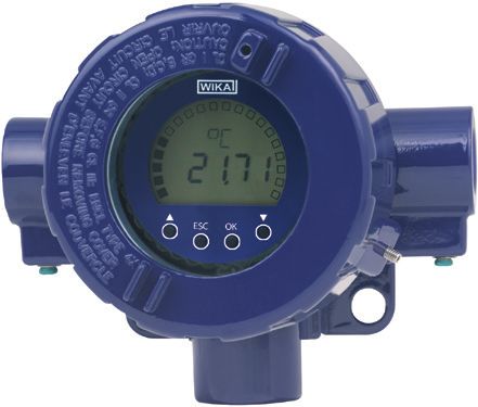
Contents

                            Contents                                                               EN

                            1. General information                                             4
                            2. Safety                                                          5
                            3. Specifications                                                  9
                            4. Design and function                                            10
                            5. Transport, packaging and storage                               12
                            6. Commissioning, operation                                       13
                            7. Electrical connection                                          15
                            8. Menu guidance                                                  17
                            9. Information on mounting and operation in hazardous areas 22
                            10. Maintenance and cleaning                                      25
                            11. Faults                                                        26
                            12. Dismounting, return and disposal                              27
                            Appendix 1: EU declaration of conformity                          28
                            Appendix 2: FM/CSA installation drawing                           29
                            Appendix 3: ATEX/IECEx installation drawing                       30
                            Appendix 4: Manufacturer's statement                              31

                            Declarations of conformity can be found online at www.wika.com.
14008548.06 09/2021 EN/DE

                             WIKA operating instructions models DIH50, DIH52                   3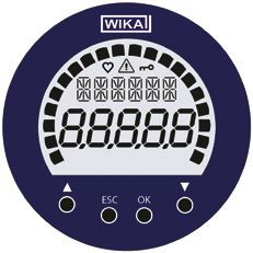
1. General information

     1. General information
     ■ The field indicators described in the operating instructions have been designed and
          manufactured using state-of-the-art technology. All components are subject to stringent
          quality and environmental criteria during production. Our management systems are
EN        certified to ISO 9001 and ISO 14001.
     ■ These operating instructions contain important information on handling the instrument.
          Working safely requires that all safety instructions and work instructions are observed.
     ■ Observe the relevant local accident prevention regulations and general safety
          regulations for the instrument‘s range of use.
     ■ The operating instructions are part of the product and must be kept in the immediate
          vicinity of the instrument and readily accessible to skilled personnel at any time.
     ■ Skilled personnel must have carefully read and understood the operating instructions,
          prior to beginning any work.
     ■ The manufacturer‘s liability is void in the case of any damage caused by using the
          product contrary to its intended use, non-compliance with these operating instructions,
          assignment of insufficiently qualified skilled personnel or unauthorised modifications to
          the instrument.
     ■ The general terms and conditions contained in the sales documentation shall apply.

     ■ Subject to technical modifications.

     ■ Further information:
          - Internet address:            www.wika.de / www.wika.com
          - Relevant data sheet:         AC 80.10
          - Application consultant:      Tel.: +49 9372 132-0
                                         Fax: +49 9372 132-406
                                         info@wika.com

     Explanation of symbols

                  WARNING!
                  ... indicates a potentially dangerous situation which can result in serious injury or
                  death if not avoided.

                  CAUTION!
                  ... indicates a potentially dangerous situation which can result in light injuries or
                                                                                                          14008548.06 09/2021 EN/DE

                  damage to the equipment or the environment if not avoided.

                  Information
                  ... points out useful tips, recommendations and information for efficient and
                  trouble-free operation.

      4                                                WIKA operating instructions models DIH50, DIH52
1. General information / 2. Safety
DANGER!
... identifies hazards caused by electric power. Should the safety instructions not
be observed, there is a risk of serious or fatal injury.
WARNING! EN
... indicates a potentially dangerous situation in the hazardous area that can
result in serious injury or death, if not avoided.
2. Safety
WARNING!
Before mounting, commissioning and operation, make sure that the display is
suitable for the application.
Non-observance can result in serious injury and/or damage to the equipment.
WARNING!
This is protection class 3 equipment for connection at low voltages, which
are separated from the power supply or voltage by greater than AC 50 V or
DC 120 V. Preferably, a connection to an SELV or PELV circuit is recommended;
alternatively protective measures from HD 60346-4-41 (DIN VDE 0100-410).
Alternatively for North America:
The connection can be made in line with “Class 2 Circuits” or “Class 2 Power
Units” in accordance with CEC (Canadian Electrical Code) or NEC (National
Electrical Code).
Further important safety instructions can be found in the individual chapters of
these operating instructions.
2.1 Intended use
The field indicators models DIH50, DIH52 are used for converting an analogue current
signal (4 … 20 mA) into an indication of the corresponding measured value and are
intended for mounting in the field.
They comprise a display and operating unit without power supply for looping in 4 … 20 mA/
HART® circuits.
The instrument has been designed and built solely for the intended use described here,
14008548.06 09/2021 EN/DE
and may only be used accordingly.
The technical specifications contained in these operating instructions must be observed.
Improper handling or operation of the instrument outside of its technical specifications
requires the instrument to be taken out of service immediately and inspected by an
authorised WIKA service engineer.
WIKA operating instructions models DIH50, DIH52 52. Safety
If the instrument is moved from a cold into a warm environment, the formation of
condensation may result in the instrument malfunctioning. Before putting it back into
operation, wait for the instrument temperature and the room temperature to equalise.
The manufacturer shall not be liable for claims of any type based on operation contrary to
EN the intended use.
2.2 Personnel qualification
WARNING!
Risk of injury if qualification is insufficient!
Improper handling can result in considerable injury and damage to equipment.
■ The activities described in these operating instructions may only be carried
out by skilled personnel who have the qualifications described below.
■ Keep unqualified personnel away from hazardous areas.
Skilled personnel
Skilled personnel are understood to be personnel who, based on their technical training,
knowledge of measurement and control technology and on their experience and
knowledge of country-specific regulations, current standards and directives, are capable of
carrying out the work described and independently recognising potential hazards.
Special operating conditions require further appropriate knowledge, e.g. of aggressive
media.
2.3 Additional safety instructions for instruments per ATEX
WARNING!
Non-observance of these instructions and their contents may result in the loss
of explosion protection.
WARNING!
Do not use field indicators with any damage to the exterior!
CAUTION!
■ Repairs are strictly prohibited.
■ Do not use displays presenting externally visible damage.
14008548.06 09/2021 EN/DE
■ Observe the instructions for mounting and operation as well as the
requirements for the use of the devices in hazardous areas.
6 WIKA operating instructions models DIH50, DIH522. Safety
2.4 Special hazards
WARNING!
Observe the information given in the applicable type examination certificate and
the relevant country-specific regulations for installation and use in hazardous
areas (e.g. IEC/EN 60079-14, NEC, CEC). Non-observance can result in serious EN
injury and/or damage to the equipment.
For further important safety instructions for instruments with ATEX approval, see
chapter 9 “Information on mounting and operation in hazardous areas”.
WARNING!
For hazardous media such as oxygen, acetylene, flammable or toxic gases or
liquids, and refrigeration plants, compressors, etc., in addition to all standard
regulations, the appropriate existing codes or regulations must also be followed.
WARNING!
To ensure safe working on the instrument, the operating company must ensure
■ that suitable first-aid equipment is available and aid is provided whenever
required,
■ that the operating personnel are regularly instructed in all topics regarding
work safety, first aid and environmental protection, and know the operating
instructions, in particular the section on safety instructions.
WARNING!
When working during a running process operation, measures to prevent
electrostatic discharge from the connecting terminals should be taken, as a
discharge could lead to temporary corruption of the measured value.
DANGER!
Danger of death caused by electric current
Upon contact with live parts, there is a direct danger of death.
■ The instrument may only be installed and mounted by skilled personnel.
■ Operation using a defective power supply unit (e.g. short circuit from the
mains voltage to the output voltage) can result in life-threatening voltages at
the instrument!
14008548.06 09/2021 EN/DE
WARNING!
Residual media in the dismounted instrument can result in a risk to persons, the
environment and equipment. Take sufficient precautionary measures.
WIKA operating instructions models DIH50, DIH52 72. Safety
2.5 Labelling, safety marks
■ Product label for whole instrument
EN
■ Product labels for indicator module
DIH50-B 2016 XXXXXXXX
4 ... 20 mA
2-wire HART ® Made in
WIKA Alexander Wiegand SE & Co. KG D-63911 Klingenberg Germany
DIH50-B 2016 XXXXXXXX
4 ... 20 mA
2-wire HART ® Made in
BVS 16 ATEX E 112 X IS, CL 1, DIV 1, Grp. A-D, T4/T5/T6
WIKA Alexander Wiegand SE & Co. KG D-63911 Klingenberg Germany
CL 1, DIV 2, Grp. A-D, T4/T5/T6
IECEx BVS 16.0075X
150135
Tamb T4/T5/T6: -40 ... +85 °C/+70 °C/+55 °C
WARNING! POTENTIAL ELECTROSTATIC CHARGING HAZARD Inst. Dwg. 11315741 0158
BVS 16 ATEX E 112 X IS, CL 1, DIV 1, Grp. A-D, T4/T5/T6
CL 1, DIV 2, Grp. A-D, T4/T5/T6
IECEx BVS 16.0075X
Tamb T4/T5/T6: -40 ... +85 °C/+70 °C/+55 °C
150135
WARNING! POTENTIAL ELECTROSTATIC CHARGING HAZARD Inst. Dwg. 11315741 0158
Model
Serial number
Ex marking
Warning note
Year of manufacture
Information on version (output signal, measuring range...)
14008548.06 09/2021 EN/DE
HART® symbol
Logos
FM marking
Installation drawing
Before mounting and commissioning the instrument, ensure you read
the operating instructions!
8 WIKA operating instructions models DIH50, DIH523. Specifications
3. Specifications
Specifications Model DIH50 Model DIH52
Display principle LCD, rotatable in 10° steps
Display measured value 7-segment LCD, 5-digit, character size 9 mm
EN
Bar graph 20-segment LCD
Information line 14-segment LCD, 6-digit, character size 5.5 mm
Status indicators ♥ : HART® mode (signalling of HART® parameter adoption)
: Unit lock
: Warnings or error messages
Indication range -9999 ... 99999
Measuring rate 4/s
Accuracy ±0.1 % of the measuring span ±0.05 % of the measuring span
Temperature coefficient ±0.1 % of the measuring span/10 K
Permitted current 100 mA
carrying capacity
Voltage drop < DC 3 V (< DC 2 V at 20 mA); supply via current loop
HART® functionality
■ Access control - Secondary master
■ Automatically set Unit, measuring range
parameters
■ Available commands - Unit, measuring range start/end,
format, zero point, span, damping,
polling address
■ Identified commands Generic mode: Generic mode:
1, 15, 35, 44 0, 1, 6, 15, 34, 35, 36, 37, 44
■ Multidrop Not supported Measured values are automatically
taken from the HART® digital data and
displayed
EMC directive EN 61326 emission (group 1, class B) and interference immunity
(industrial application)
Ambient conditions
14008548.06 09/2021 EN/DE
Ambient temperature -60 1) / -40 ... +85 °C
Functional area of the display -20 2) ... +70 °C
Vibration resistance 3 g per EN 60068-2-6
Shock resistance 30 g per EN 60068-2-27
1) Special version on request (only available with selected approvals)
2) In previous ambient temperatures < -20 °C a delayed recovery of the indication function could be expected, especially in
case of low loop current.
WIKA operating instructions models DIH50, DIH52 93. Specifications / 4. Design and function
Field case
Material Aluminium, stainless steel;
window in polycarbonate
Colour Aluminium: night blue, RAL 5022
EN Stainless steel: silver
Cable glands 3 x M20 x 1.5 or 3 x ½ NPT
Ingress protection IP66
Weight Aluminium: approx. 1.5 kg
Stainless steel: approx. 3.7 kg
Dimensions see drawing
Basic module Models DIH50-Z, DIH50-B, DIH52-Z, DIH52-B
Material Polycarbonate
Ingress protection IP20
Weight approx. 80 g
Dimensions see drawing
For further specifications see WIKA data sheet AC 80.10 and the order documentation.
For further important safety instructions for operation in hazardous areas, see
chapter 9 “Information on mounting and operation in hazardous areas”.
4. Design and function
4.1 Description
The field indicators are external display and operating units without separate power supply
for 4 … 20 mA/HART® sensors. The instruments are used for measured value display and
operation remote from the measuring point. They are looped anywhere in the 4 … 20 mA
signal line and measure the current in the current loop. At the same time, they read and
display the measured values with unit via the HART® signal.
The field indicators are powered directly from the 4 ... 20 mA current loop, with a resultant
voltage drop of less than 3 V.
14008548.06 09/2021 EN/DE
The field indicators meet the requirements of:
■ Explosion protection (depending on the version)
■ Electromagnetic compatibility in accordance with DIN EN 61326 and NAMUR
recommendation NE21
10 WIKA operating instructions models DIH50, DIH524. Design and function
Versions
Model DIH5x-Z Basic module without field case, no Ex protection
Model DIH5x-B Basic module without field case, Ex protection (intrinsically safe)
Model DIH5x-S Field indicator, no Ex protection (standard)
Model DIH5x-F Field indicator, Ex protection (flameproof enclosure) EN
Model DIH5x-I Field indicator, Ex protection (intrinsically safe)
Model DIH50 HART® slave (standard)
Model DIH52 HART® master
4.1.1 Basic module (DIH50-B, DIH50-Z, DIH52-B, DIH52-Z)
The basic modules comprise a mounting adapter with two integrated connection terminals
and connecting cables, as well as a display unit including the display and the electronics.
Both parts are connected via a cable with plug-in coupling. Depending on their design, the
basic modules can be mounted in different cases or thermometer connection heads.
1920741.01
Use cases suitable for field mounting which comply with the valid regulations and
requirements. In particular, observe the ambient conditions defined in chapter 3
“Specifications” and the requirements defined in chapter 9 “Information on mounting and
operation in hazardous areas”.
14008548.06 09/2021 EN/DE
WIKA operating instructions models DIH50, DIH52 114. Design and function / 5. Transport, packaging and storage
4.1.2 Field indicators (DIH5x-S, DIH5x-I, DIH5x-F)
The field indicators comprise a case with integrated display and operation module and a
terminal insert with two terminal blocks.
1556707.01
EN
4.2 Operation in safety-related applications
The field indicators are suitable for use in safety-related applications (required
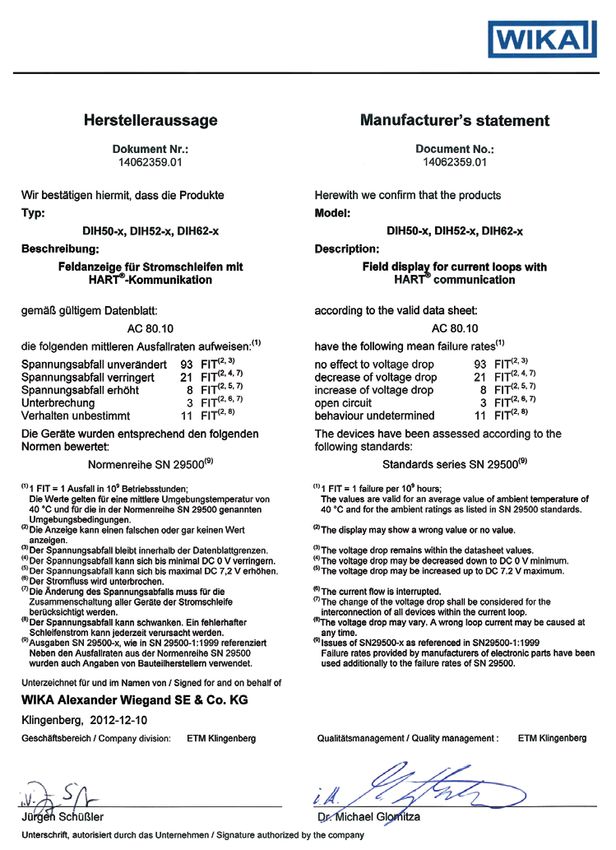
SILIEC 61508 / IEC 61511 characteristics see Appendix 4 “Manufacturer's statement”).
4.3 Scope of delivery
Cross-check the scope of delivery with the delivery note.
5. Transport, packaging and storage
5.1 Transport
Check the instrument for any damage that may have been caused by transport.
Obvious damage must be reported immediately.
5.2 Packaging
Do not remove packaging until just before mounting.
Keep the packaging as it will provide optimum protection during transport (e.g. change in
installation site, sending for repair).
14008548.06 09/2021 EN/DE
5.3 Storage
Permissible conditions at the place of storage:
■ Storage temperature: -40 ... +85 °C
■ Humidity: 35 ... 85 % relative humidity (without condensation)
12 WIKA operating instructions models DIH50, DIH525. Transport, packaging ... / 6. Commissioning, operation
Avoid exposure to the following factors:
■ Direct sunlight or proximity to hot objects
■ Mechanical vibration, mechanical shock (putting it down hard)
■ Soot, vapour, dust and corrosive gases
EN
6. Commissioning, operation
In hazardous areas, only use field indicators that are approved for those
hazardous areas. The approval is marked on the product label.
6.1 Operating modes
The following operating modes are possible:
■ HART® slave / basic mode (4 ... 20 mA)
■ HART® master / basic mode / multidrop (model DIH52)
6.1.1 Operating mode: HART® slave (models DIH50, DIH52)
The digital indicators powered via the same current loop as the corresponding transmitters
monitor permanently the HART® communication. When modifying the unit or measuring
range of the connected transmitter, the unit of the digital indicator and the corresponding
indication range are adapted automatically.
However, it is required that the unit set in the transmitter is also set in the devices.
A flashing ♥ symbol is shown on the display when a HART® communication takes place for
the first time and the digital indicators are thus switched to the HART® mode. The ♥ symbol
is displayed permanently when the HART® communication is terminated and the digital
indicator is configured according to the measuring range and the unit of the connected
transmitter.
After the power supply was interrupted or the digital indicator was set manually, the ♥
symbol is no longer displayed.
During operation in the basic mode, the ♥ symbol is not displayed.
CAUTION!
The instruments react only to the HART® standard commands 15 and 35. If
a connected HART® transmitter is configured by means of other commands,
automatic setting is not possible!
14008548.06 09/2021 EN/DE
The HART® function, i.e. the automatic adaptation of the display to the
configured data of the transmitter, requires a HART® communication between
the transmitter and the HART® software (e.g. WIKA_T32) or between the
transmitter and the field communicator (e.g. FC375/FC475, MFC4150 etc.).
WIKA operating instructions models DIH50, DIH52 136. Commissioning, operation
6.1.2 Operating mode: HART® master (model DIH52)
The master mode enables the modification of the measuring range, the unit, the format,
the damping and the polling address of the connected HART® transmitter. Further
modifications to the configuration of the transmitter (e.g. selection of the sensor) are not
possible.
EN
During the starting procedure, the field indicators try to contact the connected HART®
transmitter in the master mode and to apply its settings (unit and measuring range). During
the connection establishment, the status line shows the message “Connecting HART®”.
When a HART® sensor is detected, the HART® symbol is displayed. The field indicator
switches to the HART® mode and starts operation using the settings received from the
transmitter. This procedure is repeated whenever the power supply is switched on.
When pressing any key during the starting process or the device has not detected any
HART® transmitter during approx. 70 seconds, the digital indicator switches to the basic
mode and starts operation on the basis of the factory settings.
6.1.3 Operating mode: Multidrop (model DIH52)
In this specially defined operating state for HART® transmitters, the current signal is firmly
set to 4 mA and the measuring information is transmitted via the HART® communication
to the control room. To enable the displaying of the measured value of a transmitter, the
address of the desired transmitter must be set in the "Address" menu item.
If the HART® address is modified during operation, the establishment of a new connection
is started during which, however, the sensor must respond immediately in order to
complete the connection establishment.
The digital indicators show the measured values of the primary variable transmitted via
HART® to the control room. The display is passive, i.e. the transmission of the measured
values must be requested by the control room. The devices function as secondary master
with respect to the sensor during the parameterisation.
6.1.4 Operating mode: Basic mode, 4 ... 20 mA (models DIH50, DIH52)
In the basic mode, all settings of the digital indicator must be carried out manually by
means of the front-side keys.
To navigate in the menu levels, four keys with the following functions are available:
▲ (UP) One menu item up
▼ (DOWN) One menu item down
OK Calls the programming menu
14008548.06 09/2021 EN/DE
ESC Exits the programming menu
- Back to the previous menu level in the menu guidance
- Return from the edit function without saving the modification
see also chapter 8 “Menu guidance”
14 WIKA operating instructions models DIH50, DIH526. Commissioning, operation / 7. Electrical connection
6.2 User interface
Status data
Unit line, info line EN
Measured value
Bar graph
Operating keys
7. Electrical connection
WARNING!
Observe the safety-relevant maximum values for the connection of the power
supply and the sensors defined in chapter 9.1 “Model overview and their
approvals”.
When working on the field indicators (e.g. installation/removal, maintenance work) take
measures to prevent electrostatic discharge from the terminals.
WARNING!
Carry out mounting work only with power disconnected!
Use the recommended cables and tighten the cable gland. Lead the connecting cable
downward before of the cable gland in order to provide additional protection of the device
against penetration of liquids. Rain water and condensed water can thus drip.
The device is connected by means of a commercially available two-wire cable without
screen. If electromagnetic interference exceeding the test values of EN 61326 for industrial
areas is to be expected or the HART® multidrop mode is used, a screened cable must
be used. Use cables with round cross section. An outside diameter of cable of 5 ... 9 mm
(0.2 … 0.35 inch) guarantees the tightness of the cable gland. When using other diameters
or cross sections, the gasket must be replaced or a suitable cable gland must be used.
14008548.06 09/2021 EN/DE
Connect the cable screen on both sides to earth potential if a screened cable is required.
Connect the screen in the sensor directly to the internal earth terminal. The external earth
terminal of the case must be connected with low impedance to the equipotential bonding.
WIKA operating instructions models DIH50, DIH52 157. Electrical connection
CAUTION!
If equipotential bonding currents are to be expected, a ceramic capacitor
(e.g. 1 nF, 1,500 V) must be used for the connection on the evaluation side. The
low-frequency equipotential bonding currents are thus suppressed, but the
high-frequency interference signals remain.
EN
Field indicators models DIH50, DIH52
Open the case cover, push one of the two black fastening clips backwards and pull the
display module upwards. The power supply is connected at the front via the Philips screws
of the display module. Connect the positive pole of the power supply to the terminal marked
with ⊕ and the negative pole of the power supply to the terminal marked with ⊖.
The signal line of the transmitter is to be connected to the terminal blocks inside the field
case. To do so, connect the positive pole of the signal line to the terminal marked with ⊕
(red cable) and the negative pole of the signal line to the terminal marked with ⊖ (black
cable).
Non-hazardous area Ex area
Voltage supply DIH50, DIH52
spring-loaded
Transmitter
push terminals
red
black
Load
With flexible leads we recommend the use of crimped
connector sleeves.
The integrated reverse polarity protection (wrong polarity
on the terminals ⊕ and ⊖) prevents the digital indicator
from damage.
The following maximum values are applicable:
without explosion protection: 42 V
with explosion protection: 30 V
The connected wires must be checked to ensure they are connected properly. Only
well-secured wires can guarantee a fault-free operation.
14008548.06 09/2021 EN/DE
Recommended tools for terminal screws:
Model Screwdriver Tightening torque
DIH50, Cross head ('Pozidriv' tip) 0.4 Nm
DIH52 size 2 (ISO 8764)
16 WIKA operating instructions models DIH50, DIH528. Menu guidance
8. Menu guidance
Main menu Submenu 1 Submenu 2
Measurement Unit EN
Measuring range start
Measuring range end
Measuring range format
Span
Zero
Damping
Adress
Display Unit
Unit lock
Display format
Filter
Alarm on/off
Low alarm
High alarm
Min/Max memory delete
display yes/no
Configuration Language
Contrast
Reset
User unit
Min. failure message
14008548.06 09/2021 EN/DE
Max. failure message
Firmware version
Password
Logout
WIKA operating instructions models DIH50, DIH52 178. Menu guidance
8.1 Main menu “Measurement”
EN
Function Factory setting
Unit mA
Setting the unit of the measuring range of the connected transmitter
Setting range:
mA → Ω → bar → mbar → psi → hPa → kPa → mmH2O → mH2O → inHg → °C →
°F → K → % → USER → V
Measuring range start 4,000
Setting of the start value of the measuring range of the connected transmitter
(e.g. -30 for a measuring range of -30 ... +120 °C)
Setting range: -9999 ... 99999
Measuring range end 20,000
Setting the end value of the measuring range of the connected transmitter (e.g.
120 for a measuring range of -30 ... +120 °C)
Setting range: -9999 ... 99999
Measuring range format 0.000
Setting the decimal point for the measuring range of the connected transmitter.
Setting range: 0 ↔ 0.0 ↔ 0.00 ↔ 0.000 ↔ 0.0000
Span (only DIH52) -----
The current measured value is applied as max. adjustment for the sensor.
Attention: Cannot be used for all HART® transmitters
Zero point (only DIH52) -----
The current measured value is applied as min. adjustment for the sensor.
Attention: Cannot be used for all HART® transmitters
Damping (only DIH52) 0.0
Input damping for damping the measured value.
Setting range: 0.0 … 999
Adress (only DIH52) 0
Setting the HART® address of the assigned transmitter in the multidrop mode;
for the standard current loop mode, this address must always be set to 0.
Setting range: 0 ... 15
14008548.06 09/2021 EN/DE
18 WIKA operating instructions models DIH50, DIH528. Menu guidance
8.2 Main menu “Display”
EN
Function Factory setting
Unit mA
Setting the unit for the display of the digital indicator
Here, you can select a unit deviating from the unit of the measuring range of the
connected transmitter. The measured values are then converted automatically
into the deviating unit.
However, only units of the same unit group as the set unit of the measuring
range may be selected.
Setting range (according to unit groups):
- Electrical measurement parameters: V, mA, Ω
- Pressure: bar, mbar, psi, hPa, kPa, mmH2O, mH2O, inHg
- Temperature: °C, °F, K
- Others: %, USER
Unit lock UnLoC
By activating the unit lock, the set display unit is locked to protect the unit
against modifications. The display shows the sign . Modifications of the
measuring range are converted automatically.
The unit lock only functions if the units of the measuring range and the display
originate from the same unit group.
When connecting a transmitter and its configuration via HART® with a unit of
another unit group, then the unit lock is deactivated. In this case, the display unit
is set according to the configured measuring range unit.
Setting range:
- not locked (UnLoC)
- locked (LoC)
Indication range format 0.000
Setting the decimal point for the indication range of the digital indicator
Setting range: 0 ↔ 0.0 ↔ 0.00 ↔ 0.000 ↔ 0.0000
Filter 0
Activation of the digital filter of the 1st order;
Setting range: 0 ... 10
Alarm -----
14008548.06 09/2021 EN/DE
From this menu item it is possible to branch into the submenu 2 for the alarm
configuration by selecting SELECT.
Min/Max memory -----
From this menu item it is possible to branch into the submenu 2 for the min./
max. memory by selecting SELECT.
WIKA operating instructions models DIH50, DIH52 198. Menu guidance
8.2.1 Submenu “Alarm”
EN
Function Factory setting
On/off OFF
Activating or deactivating the alarm function;
if a value exceeds or falls below a set alarm limit, the display shows the warning
symbol and the measured value starts flashing.
Setting range:
- OFF
- ON
Low alarm 4,000
Setting the value which releases the alarm function when this value is not
reached.
Setting range:
Start value of the indication range up to the set value of the high alarm
High alarm 20,000
Setting the value upon exceeding of which the alarm function is released.
Setting range:
Set value of the low alarm up to the end value of the indication range
8.2.2 Submenu “Min/Max memory"
Function Factory setting
Delete min/max dEL
Function for deleting the maximal value memory
Pressing the SELECT key twice deletes the maximum value memory.
Min/max on/off OFF
Activation of the min./max. display;
If the min./max. display is switched on, the display switches cyclically between
14008548.06 09/2021 EN/DE
the current measured value (display time 5 s), the minimum value and the
maximum value (display time 2 s).
For the display of the maximum values, the unit on the display is replaced by
min. or max.
Setting range:
- OFF
- ON
20 WIKA operating instructions models DIH50, DIH528. Menu guidance
8.3 Main menu “Configuration”
EN
Function Factory setting
Language EnG
Setting the language
Setting range:
- dEU (GEr): German
- EnG: English
Contrast 2
Setting range:
1-4
Reset -----
A reset is used to reset all settings of the digital indicator to the factory settings.
The SELECT key must be pressed twice to activate the reset.
After pressing the key once, the RESET display starts flashing and after the
second actuation of the key, the display is completely hidden and the reset is
carried out.
USER-unit USER
The user can freely program a 6-digit user unit.
The 6 characters can be selected from an alphanumeric character set.
By pressing the SELECT key, the first digit is enabled and starts flashing. Use
the arrow keys to select the desired character. By pressing the SELECT key
again, the character is confirmed and the next digit is enabled.
Min. failure message 3.6
Setting the current value which releases the min. failure message when this
value is reached or not reached.
The min. failure message is displayed with 5 underscores (_ _ _ _ _) and the
message OUTMIN.
Setting range: 3.5 ... 3.9 mA
Max. failure message 21.0
Setting the current value upon reaching or exceeding of which the max. failure
message is released.
The max. failure message is displayed with 5 upper scores (_ _ _ _ _) and the
message OUTMAX.
Setting range: 20.1 ... 21.5 mA
14008548.06 09/2021 EN/DE
Firmware version -----
The number of the firmware version used is displayed.
WIKA operating instructions models DIH50, DIH52 218. Menu guidance / 9. Information on mounting and ...
Function Factory setting
Password 123456
The menu area “Measurement” as well as the function “Reset” are protected by
a password. For the access, a login by entering the password is required. The
EN login is displayed, if you try to use one of the protected functions. All functions
are accessible after a successful login. The logoff is carried out in the menu
item “Logout” or automatically after 3 minutes without user activity.
The password has max. 6 characters and can be modified in the menu item
“Password”. For this purpose, the actual password is entered and confirmed
with “OK” until the string “******” appears. With “OK” the entered password is
edited again and can now be modified.
Logout -----
This menu item enables the early logout after entering the password.
9. Information on mounting and operation in hazardous areas
In hazardous areas, only use field indicators that are approved for those hazardous areas.
The approval is marked on the product label.
When connecting them to other devices or component, observe the connection
requirements regarding explosion protection, such as maximum admissible voltage, power
or load with capacitances (see chapter 9.2 to 9.4).
9.1 Model overview and their approvals
Model Approvals Ambient/storage Safety-related Power
temperature (in maximum supply
accordance with the values for UB (DC)
relevant temperature current loop
classes) (± connections)
DIHxx-S without -20 ... +85 °C - 14.5 ... 42 V
DIHxx-Z without -20 ... +85 °C - 14.5 ... 42 V
DIH50-B BVS 16 ATEX E 112 X -40 ... +85 °C at T4 Ui < 29 V 14.5 ... 29 V
DIH52-B IECEx BVS 16.0075X -40 ... +70 °C at T5 Ii < 100 mA
-40 ... +55 °C at T6 Pi < 680 mW
BVS 16 ATEX E 112 X -40 ... +40 °C Ci = 13.2 nF
IECEx BVS 16.0075X (Pi = 680 mW) Li = 1.2 μH
-40 ... +70 °C
(Pi = 650 mW)
14008548.06 09/2021 EN/DE
DIH50-B CSA (1946893, LR 66027) -40 ... +85 °C at T4 Ui = 29 V 14.5 ... 29 V
Class I, Division 1 + 2, Groups A, B, -40 ... +70 °C at T5 (Vmax < 29 V)
C, D -40 ... +55 °C at T6 Ii = 100 mA
(Imax < 100 mA)
Pi = 660 mW
(Pmax < 660 mW)
Ci = 12 nF
Li = 2.2 μH
22 WIKA operating instructions models DIH50, DIH529. Information on mounting and operation in hazardous areas
Model Approvals Ambient/storage Safety-related Power
temperature (in maximum supply
accordance with the values for UB (DC)
relevant temperature current loop
classes) (± connections)
DIH50-B FM (FM19US0033X) -40 ... +85 °C at T4 Ui = 29 V 14.5 ... 29 V EN
Class I, Division 1, Groups A, B, C, D -40 ... +70 °C at T5 Ii = 100 mA
(IS/I/1/ABCD/T* + IS/I/0AEx ia/IIC/T*) -40 ... +55 °C at T6 Pi = 680 mW
Ci = 13.2 nF
Class I, Division 2, Groups A, B, C, D Li = 1.2 μH
NI/I/2/ABCD/T* + NI/I/2/IIC/T*
DIH50-B EAC (ТС RU C-DE.ГБ08.02128) -60 1) /-40 ... +85 °C at T4 Ui = 29 V 14.5 ... 29 V
0 Ex ia IIC T4/T5/T6 -60 1) /-40 ... +75 °C at T5 (Vmax < 29 V)
1 Ex ib [ia] IIC T4/T5/T6 -60 1) /-40 ... +55 °C at T6 Ii = 100 mA
(Imax < 100 mA)
DIP A20 Ta 120 °C
Pi = 660 mW
DIP A21 Ta 120 °C
(Pmax < 660 mW)
Ci = 12 nF
Li = 2.2 μH
DIH5x-F Flameproof enclosure -40 ... +85 °C at T4 UM = 30 V 14.5 ... 30 V
BVS 10 ATEX E 158 -40 ... +75 °C at T5 PM = 2 W
IECEx BVS 10.0103 -40 ... +60 °C at T6
II 2G Ex db IIC T4/T5/T6 Gb
Ex db IIC T4/T5/T6 Gb
DIH5x-F Flameproof enclosure -60 1) /-40 ... +85 °C at T4 UM = 30 V 14.5 ... 30 V
ТС RU C-DE.ГБ08.02128 -60 1) /-40 ... +75 °C at T5 PM = 2 W
1 Ex d IIC T6 ... T4 -60 1) /-40 ... +55 °C at T6
DIH5x-I Intrinsically safe equipment 2) -40 ... +85 °C at T4 Ui ≤ 29 V 14.5 ... 29 V
BVS 16 ATEX E 112 X -40 ... +70 °C at T5 Ii ≤ 100 mA
IECEx BVS 16.0075X -40 ... +55 °C at T6 Pi ≤ 680 mW
-40 ... +40 °C Ci = 13.2 nF
II 2(1)G IIC T4/T5/T6 Gb
(Pi = 680 mW) Li = 1.2 μH
II 2(1)D Ex ia [ia Da] IIIC T135 °C Db
II 2G Ex ia IIC T4/T5/T6 Gb -40 ... +70 °C
II 2D Ex ia IIIC T135 °C Db (Pi = 650 mW)
DIH5x-I Intrinsically safe equipment 2) -60 1) /-40 ... +85 °C at T4 Ui ≤ 29 V 14.5 ... 29 V
ТС RU C-DE.ГБ08.02128 -60 1) /-40 ... +70 °C at T5 Ii ≤ 100 mA
0 Ex ia IIC T4/T5/T6 -60 1) /-40 ... +55 °C at T6 Pi ≤ 680 mW
1 Ex ib [ia ] IIC T4/T5/T6 -60 1) /-40 ... +40 °C Ci = 13.2 nF
(Pi = 680 mW) Li = 1.2 μH
DIP A20 Ta 120 °C
DIP A21 Ta 120 °C -60 1) /-40 ... +70 °C
(Pi = 650 mW)
1) Special version on request (only available with selected approvals)
14008548.06 09/2021 EN/DE
2) The installation conditions for the display must be considered for the final application.
Output circuit DIH50-B, DIH52-B, DIH50-I, DIH52-I:
Uo = DC 29.8 V
Io = 109.2 mA
Po = 680 mW
WIKA operating instructions models DIH50, DIH52 239. Information on mounting and operation in hazardous areas
9.2 Specific conditions for safe use, models DIH5x-I
Installation in areas requiring EPL Ga or EPL Gb equipment
■ Electronic assemblies of field indicator models DIH5x-I shall be mounted inside a case
suitable for installation in EPL Ga or Gb area respectively, wherein electrostatic charge
EN effects are excluded. The case shall provide, as a minimum, a degree of protection of
IP20 according to IEC 60529.
■ Wiring inside this case shall satisfy the conditions of clause 6.3.12 and clause 7.6.e of
IEC 60079-11:2011.
■ Terminals or connectors for the intrinsically safe circuits shall be arranged in line with
clause 6.2.1 or 6.2.2 of IEC 60079-11:2011, respectively.
Installation in areas requiring EPL Da or EPL Db equipment
■ Electronic assemblies of field indicator models DIH5x-I shall be mounted inside a case
suitable for installation in EPL Da or Db area respectively, wherein electrostatic charge
effects are excluded. The case shall provide, as a minimum, a degree of protection of
IP5x (group IIIB application) or IP6x (group IIIC application) according to IEC 60529.
■ Wiring inside this case shall satisfy the conditions of clause 6.3.12 and clause 7.6.e of
IEC 60079-11:2011.
■ Terminals or connectors for the intrinsically safe circuits shall be arranged in line with
clause 6.2.1 or 6.2.2 of IEC 60079-11:2011, respectively.
9.3 Intrinsically safe supply and signal circuit, models DIHxx-B, DIHxx-NT
(4 ... 20 mA loop; terminal ⊕ and ⊖)
Parameters Models DIH5x-B, DIH5x-I
Voltage Ui / U0 29 V
Strenght of current Ii / I0 100 mA
Power Pi 680 mW
Effective internal capacitance Ci 13.2 nF
Effective internal inductance Li 1.2 μH
14008548.06 09/2021 EN/DE
24 WIKA operating instructions models DIH50, DIH529. Information on mounting ... / 10. Maintenance and cleaning
According to the temperature class, these field indicators may only be used in the following
ambient temperature ranges:
Application Ambient temperature range Temperature Power Pi
class Models DIH5x-B, DIH5x-I
Group II -60 3) / -50 4) / -40 °C ≤ Ta ≤ +85 °C T4 < 680 mW EN
-60 3) / -50 4) / -40 °C ≤ Ta ≤ +70 °C T5 < 680 mW
-60 3) / -50 4) / -40 °C ≤ Ta ≤ +55 °C T6 < 680 mW
Dust Ex -60 3) / -50 4) / -40 °C ≤ Ta ≤ +70 °C n.a. < 650 mW
-60 3) / -50 4) / -40 °C ≤ Ta ≤ +40 °C n.a. < 680 mW
n. a. = not applicable
3) Special version on request (only available with selected approvals)
4) Special version
9.4 Specific conditions for safe use, models DIH50-F, DIH52-F
Cables, insertions and blind plugs must be suitable for the corresponding operating
temperature. You must therefore check in the application case (e.g. ambient temperature
plus 5 K) whether the components used are suitable. The instruments may not be opened
while they are under voltage.
Observe the warnings on the instruments:
“WARNING! - do not open while under voltage”
10. Maintenance and cleaning
10.1 Maintenance
The field indicators described here are maintenance-free.
The electronics are completely encapsulated and incorporate no components which could
be repaired or replaced.
Repairs must only be carried out by the manufacturer.
10.2 Cleaning
CAUTION!
■ Prior to cleaning, switch off and disconnect the instrument from the mains.
■ Clean the instrument with a moist cloth.
14008548.06 09/2021 EN/DE
■ Electrical connections must not come into contact with moisture.
■ Wash or clean the dismounted instrument before returning it in order to protect
personnel and the environment from exposure to residual media.
For information on returning the instrument see chapter 12.1 “Return”.
WIKA operating instructions models DIH50, DIH52 2511. Faults
11. Faults
Fault-tree
Current loop disconnected
EN
l = 0 mA Transmitter not connected
Voltage supply connected incorrectly
(wrong polarity)
l > 20 mA Process temperature out of range
l < 4 mA Sensor break or short circuit
Sensor connected incorrectly
4 mA < l < 20 mA Wrong transmitter configuration
but wrong values
Error messages
HART® communications errors are reported with the numerical codes 1 - 9. An error
message occurs when a transaction is not successful, despite being retried several times.
An error message is only displayed when an error occurs as a consequence of a command
sent from the display, i.e. only when an operation by the user leads to the error. Errors in the
communication between the control system and sensor are detected but not displayed.
The measuring value line shows “ERROR”, the status line shows “HART® n” whereby “n”
represents the numeric error code. The error message remains displayed until the next key
actuation takes place.
The following table shows the error codes and information regarding the failure cause and
elimination.
Error code Description Causes
1 Transmitter does not respond
2 Communication error ■ Parity, check sum, package length incorrect
upon receiving
■ Transmitter signals receive error
14008548.06 09/2021 EN/DE
3 Command not implemented Command not supported by the transmitter
4 Range error ■ The value is outside the range supported by
the sensor
■ The desired unit of measure is not supported
5 Unspecified error of the The sensor signals an error in the status byte that
transmitter is not broken down
26 WIKA operating instructions models DIH50, DIH5211. Faults / 12. Dismounting, return and disposal
CAUTION!
If faults cannot be eliminated by means of the measures listed above, the
instrument must be shut down immediately, and it must be ensured that signal
is no longer present, and it must be prevented from being inadvertently put back
into service. In this case, contact the manufacturer.
If a return is needed, follow the instructions given in chapter 12.1 “Return”. EN
12. Dismounting, return and disposal
WARNING!
Residual media in the dismounted instrument can result in a risk to persons, the
environment and equipment. Take sufficient precautionary measures.
12.1 Return
WARNING!
Absolutely observe the following when shipping the instrument:
All instruments delivered to WIKA must be free from any kind of hazardous
substances (acids, leachate, solutions, etc.).
When returning the instrument, use the original packaging or a suitable transport package.
To avoid damage:
1. Wrap the instrument in an antistatic plastic film.
2. Place the instrument, along with shock-absorbent material, in the packaging.
Place shock-absorbent material evenly on all sides of the shipping box.
3. If possible, place a bag containing a desiccant inside the packaging.
4. Label the shipment as carriage of a highly sensitive measuring instrument.
The return form can be found under the heading 'Service' at www.wika.com.
12.2 Disposal
Incorrect disposal can put the environment at risk.
Dispose of instrument components and packaging materials in an environmentally
compatible way and in accordance with the country-specific waste disposal regulations.
14008548.06 09/2021 EN/DE
WIKA operating instructions models DIH50, DIH52 27Appendix 1: EU declaration of conformity
EN
14008548.06 09/2021 EN/DE
28 WIKA operating instructions models DIH50, DIH52Appendix 2: FM/CSA installation drawing
EN
14008548.06 09/2021 EN/DE
WIKA operating instructions models DIH50, DIH52 29EN
30
Installation drawing field indicators: DIH50-I, DIH52-I with built in WIKA digital indicator module DIH50-B
Hazardous area Non-hazardous area
Example for information only! Models DIH50-I, DIH52-I Example for information only!
Provided by end-user in the Provided by end-user in the end
end use application! Transmitter use application!
spring-loaded
push terminals DIH5x-B
Cable Cable
Sensor
Power supply
Example: External transmitter Marking field indicator DIH50-I Example: Power supply
(e.g. T32.1S.0IS) ATEX (e.g. P&F KFD2-STC4 Ex1)
Ui = DC 30 V IECEx U0 = DC 25.4 V
Ii = 130 mA II (1) 2G Ex ia [ia Ga] IIC T4/T5/T6 Gb I0 = 86.8 mA
Pi = 800 W II (1) 2D Ex ia [ia Da] IIIC T120 °C Db P0 = 551 mW
Ci = 7.8 nF + Cicable C0 = 93 nF
Li = 100 µH + Licable L0 = 4,600 µH
Entity parameters DIH50-I, Entity parameters
DIH52-I: DIH50-I, DIH52-I: Example: Entity parameters comparison
Example: Entity parameters comparison U0 = DC 29.8 V Ui = DC 29 V DIH50-I, DIH52-I: KFD2-STC4 Ex1:
T32.1S.0IS: DIH50-I, DIH52-I (with power I0 = 109.2 mA Ii = 100 mA Ui = DC 29 V ≥ U0 = DC 25.4 V
supply and reduction): P0 = 680 mW Ii = 100 mA ≥ I0 = 86.8 mA
C0 = value according to the Pi = 680 mW
Ui = DC 30 V ≥ U0 = DC 26.2 V Pi = 680 mW ≥ P0 = 551 mW
certified IS power supply Ci = 13.2 nF *
Ii = 130 mA ≥ I0 = 96 mA Ci = 13.2 nF 1) ≤ C0 = 93 nF
reduced by 13.2 nF Li = 1.2 µH *
Pi = 800 mW ≥ P0 = 551 mW Li = 1.2 µH 2) ≤ L0 = 4,600 µH
Ci = 7.8 nF + CiCable ≤ C0 = 93 nF - 13.2 nF = 79.8 nF L0 = value according to the U0 = DC 29.8 V
Li = 100 µH + LiCable ≤ L0 = 4,600 µH - 1.2 µH certified IS power supply *The internal wiring is l0 = 109.2 mA
= 4,598.8 µH reduced by 1.2 µH negligible (≤ 3 m) 1) Ci = 13.2 nF + Ci-value of the connected and certified
transmitter + CiCable
Appendix 3: ATEX/IECEx installation drawing
2) Li = 1.2 µH + Li-value of the connected and certified
transmitter + LiCable
Remark: Summarised requirements for field indicator WIKA DIH50-I, DIH52-I:
Due to the segregation requirements Special conditions for a safe use: None
of the applied standards, IS-supply- Ambient temperature range and temperature classification
and signal-circuit and the IS sensor field indicator DIH50-I, DIH52-I
circuit shall be considered as being Ambient IIC (-50) 1) -40 °C ≤ Ta ≤ +85 °C (T4)
galvanically connected to each other; temperature (-50) 1) -40 °C ≤ Ta ≤ +70 °C (T5)
functional separation provided. range (-50) 1) -40 °C ≤ Ta ≤ +55 °C (T6)
IIIC (-50) 1) -40 °C ≤ Ta ≤ +40 °C (Pi = 680 mW)
(-50) 1) -40 °C ≤ Ta ≤ +70 °C (Pi = 650 mW)
1) The values in brackets are valid for special low temperature versions 14041464.02
WIKA operating instructions models DIH50, DIH52
(only limited transmitter combination for series DIHxx-I possible).
14008548.06 09/2021 EN/DEAppendix 4: Manufacturer's statement
EN
14008548.06 09/2021 EN/DE
WIKA operating instructions models DIH50, DIH52 31EN
14008548.06 09/2021 EN/DE
32 WIKA operating instructions models DIH50, DIH52Inhalt
Inhalt
1. Allgemeines 34 DE
2. Sicherheit 35
3. Technische Daten 39
4. Aufbau und Funktion 40
5. Transport, Verpackung und Lagerung 42
6. Inbetriebnahme, Betrieb 43
7. Elektrischer Anschluss 45
8. Menüführung 47
9. Hinweise zu Montage und Betrieb im explosionsgefährdeten
Bereich 52
10. Wartung und Reinigung 55
11. Störungen 56
12. Demontage, Rücksendung und Entsorgung 57
Anlage 1: EU-Konformitätserklärung 58
Anlage 2: Installation drawing FM/CSA 59
Anlage 3: Installation drawing ATEX/IECEx 60
Anlage 4: Herstelleraussage 61
Konformitätserklärungen finden Sie online unter www.wika.de.
14008548.06 09/2021 EN/DE
WIKA Betriebsanleitung Typen DIH50, DIH52 331. Allgemeines
1. Allgemeines
■ Die in der Betriebsanleitung beschriebenen Feldanzeigen werden nach dem aktuellen
Stand der Technik konstruiert und gefertigt.
Alle Komponenten unterliegen während der Fertigung strengen Qualitäts- und Umwelt-
kriterien. Unsere Managementsysteme sind nach ISO 9001 und ISO 14001 zertifiziert.
■ Diese Betriebsanleitung gibt wichtige Hinweise zum Umgang mit dem Gerät. Voraus-
setzung für sicheres Arbeiten ist die Einhaltung aller angegebenen Sicherheitshinweise
DE und Handlungsanweisungen.
■ Die für den Einsatzbereich des Gerätes geltenden örtlichen Unfallverhütungsvorschrif-
ten und allgemeinen Sicherheitsbestimmungen einhalten.
■ Die Betriebsanleitung ist Produktbestandteil und muss in unmittelbarer Nähe des
Gerätes für das Fachpersonal jederzeit zugänglich aufbewahrt werden.
■ Das Fachpersonal muss die Betriebsanleitung vor Beginn aller Arbeiten sorgfältig
durchgelesen und verstanden haben.
■ Die Haftung des Herstellers erlischt bei Schäden durch bestimmungswidrige Verwen-
dung, Nichtbeachten dieser Betriebsanleitung, Einsatz ungenügend qualifizierten
Fachpersonals sowie eigenmächtiger Veränderung am Gerät.
■ Es gelten die allgemeinen Geschäftsbedingungen in den Verkaufsunterlagen.
■ Technische Änderungen vorbehalten.
■ Weitere Informationen:
- Internet-Adresse: www.wika.de / www.wika.com
- zugehöriges Datenblatt: AC 80.10
- Anwendungsberater: Tel.: +49 9372 132-0
Fax: +49 9372 132-406
info@wika.de
Symbolerklärung
WARNUNG!
... weist auf eine möglicherweise gefährliche Situation hin, die zum Tod oder zu
schweren Verletzungen führen kann, wenn sie nicht gemieden wird.
VORSICHT!
... weist auf eine möglicherweise gefährliche Situation hin, die zu geringfügigen
14008548.06 09/2021 EN/DE
oder leichten Verletzungen bzw. Sach- und Umweltschäden führen kann, wenn
sie nicht gemieden wird.
Information
... hebt nützliche Tipps und Empfehlungen sowie Informationen für einen
effizienten und störungsfreien Betrieb hervor.
34 WIKA Betriebsanleitung Typen DIH50, DIH521. Allgemeines / 2. Sicherheit
GEFAHR!
... kennzeichnet Gefährdungen durch elektrischen Strom. Bei Nichtbeachtung der
Sicherheitshinweise besteht die Gefahr schwerer oder tödlicher Verletzungen.
WARNUNG!
... weist auf eine möglicherweise gefährliche Situation im explosionsgefährdeten
Bereich hin, die zum Tod oder zu schweren Verletzungen führen kann, wenn sie
nicht gemieden wird.
DE
2. Sicherheit
WARNUNG!
Vor Montage, Inbetriebnahme und Betrieb sicherstellen, dass die Anzeige für
den Anwendungsfall geeignet ist.
Bei Nichtbeachten können schwere Körperverletzungen und/oder Sachschäden
auftreten.
WARNUNG!
Dies ist ein Betriebsmittel der Schutzklasse 3 zum Anschluss an Kleinspan-
nungen, die von der Netzspannung oder Spannung größer AC 50 V bzw.
DC 120 V getrennt sind. Zu bevorzugen ist ein Anschluss an SELV- oder
PELV-Stromkreise; alternativ ist eine Schutzmaßnahme aus HD 60346-4-41
(DIN VDE 0100-410) zu empfehlen.
Alternativ für Nordamerika:
Der Anschluss kann auch an „Class 2 Circuits“ oder „Class 2 Power Units“
gemäß CEC (Canadian Electrical Code) oder NEC (National Electrical Code)
erfolgen.
Weitere wichtige Sicherheitshinweise befinden sich in den einzelnen Kapiteln
dieser Betriebsanleitung.
2.1 Bestimmungsgemäße Verwendung
Die Feldanzeigen Typen DIH50, DIH52 dienen der Umwandlung eines analogen Strom-
signals (4 … 20 mA) in eine Anzeige des entsprechenden Messwertes und sind zur
Montage im Feld bestimmt.
Sie bestehen aus Anzeige- und Bedieneinheit ohne Hilfsenergie zum Einschleifen in
14008548.06 09/2021 EN/DE
4 … 20 mA/HART®-Stromkreise.
Das Gerät ist ausschließlich für den hier beschriebenen bestimmungsgemäßen Verwen-
dungszweck konzipiert und konstruiert und darf nur dementsprechend verwendet werden.
WIKA Betriebsanleitung Typen DIH50, DIH52 352. Sicherheit
Die technischen Spezifikationen in dieser Betriebsanleitung sind einzuhalten. Eine
unsachgemäße Handhabung oder ein Betreiben des Gerätes außerhalb der technischen
Spezifikationen macht die sofortige Stilllegung und Überprüfung durch einen autorisierten
WIKA-Servicemitarbeiter erforderlich.
Wird das Gerät von einer kalten in eine warme Umgebung transportiert, so kann durch
Kondensatbildung eine Störung der Gerätefunktion eintreten. Vor einer erneuten Inbetrieb-
nahme die Angleichung der Gerätetemperatur an die Raumtemperatur abwarten.
DE Ansprüche jeglicher Art aufgrund von nicht bestimmungsgemäßer Verwendung sind
ausgeschlossen.
2.2 Personalqualifikation
WARNUNG!
Verletzungsgefahr bei unzureichender Qualifikation!
Unsachgemäßer Umgang kann zu erheblichen Personen- und Sachschäden
führen.
■ Die in dieser Betriebsanleitung beschriebenen Tätigkeiten nur durch Fachper-
sonal nachfolgend beschriebener Qualifikation durchführen lassen.
■ Unqualifiziertes Personal von den Gefahrenbereichen fernhalten.
Fachpersonal
Das Fachpersonal ist aufgrund seiner fachlichen Ausbildung, seiner Kenntnisse der Mess-
und Regelungstechnik und seiner Erfahrungen sowie Kenntnis der landesspezifischen
Vorschriften, geltenden Normen und Richtlinien in der Lage, die beschriebenen Arbeiten
auszuführen und mögliche Gefahren selbstständig zu erkennen.
Spezielle Einsatzbedingungen verlangen weiteres entsprechendes Wissen, z. B. über
aggressive Medien.
2.3 Zusätzliche Sicherheitshinweise für Geräte nach ATEX
WARNUNG!
Die Nichtbeachtung dieser Inhalte und Anweisungen kann zum Verlust des
Explosionsschutzes führen.
WARNUNG!
Äußerlich beschädigte Feldanzeige nicht verwenden!
14008548.06 09/2021 EN/DE
VORSICHT!
■ Reparaturen sind grundsätzlich verboten.
■ Anzeigen mit äußerlichen Beschädigungen nicht verwenden.
■ Hinweise zur Montage und zum Betrieb beachten, ebenso die Vorschriften für
den Einsatz von Geräten in Ex-Bereichen.
36 WIKA Betriebsanleitung Typen DIH50, DIH522. Sicherheit
2.4 Besondere Gefahren
WARNUNG!
Die Angaben der geltenden Baumusterprüfbescheinigung sowie die jeweiligen
landesspezifischen Vorschriften zur Installation und Einsatz in explosionsgefähr-
deten Bereichen (z. B. IEC/EN 60079-14, NEC, CEC) einhalten. Bei Nichtbeach-
ten können schwere Körperverletzungen und/oder Sachschäden auftreten.
Weitere wichtige Sicherheitshinweise für Geräte mit ATEX-Zulassung siehe
Kapitel 9 „Hinweise zu Montage und Betrieb im explosionsgefährdeten Bereich“. DE
WARNUNG!
Bei gefährlichen Messstoffen wie z. B. Sauerstoff, Acetylen, brennbaren oder
giftigen Stoffen, sowie bei Kälteanlagen, Kompressoren etc. müssen über die
gesamten allgemeinen Regeln hinaus die einschlägigen Vorschriften beachtet
werden.
WARNUNG!
Für ein sicheres Arbeiten am Gerät muss der Betreiber sicherstellen,
■ dass eine entsprechende Erste-Hilfe-Ausrüstung vorhanden ist und bei
Bedarf jederzeit Hilfe zur Stelle ist.
■ dass das Bedienpersonal regelmäßig in allen zutreffenden Fragen von
Arbeitssicherheit, Erste-Hilfe und Umweltschutz unterwiesen wird, sowie die
Betriebsanleitung und insbesondere die darin enthaltenen Sicherheitshinwei-
se kennt.
WARNUNG!
Bei Arbeiten während eines laufenden Prozessbetriebes Maßnahmen zur
Vermeidung elektrostatischer Entladung auf die Anschlussklemmen treffen,
da Entladungen zu vorübergehenden Verfälschungen des Messwertes führen
können.
GEFAHR!
Lebensgefahr durch elektrischen Strom
Bei Berührung mit spannungsführenden Teilen besteht unmittelbare
Lebensgefahr.
■ Einbau und Montage des Gerätes dürfen nur durch Fachpersonal erfolgen.
■ Bei Betrieb mit einem defekten Netzgerät (z. B. Kurzschluss von Netzspan-
14008548.06 09/2021 EN/DE
nung zur Ausgangsspannung) können am Gerät lebensgefährliche Spannun-
gen auftreten!
WARNUNG!
Messstoffreste im ausgebauten Gerät können zur Gefährdung von Personen,
Umwelt und Einrichtung führen. Ausreichende Vorsichtsmaßnahmen ergreifen.
WIKA Betriebsanleitung Typen DIH50, DIH52 372. Sicherheit
2.5 Beschilderung, Sicherheitskennzeichnungen
■ Typenschild Gesamtgerät
DE
■ Typenschilder Anzeigemodul
DIH50-B 2016 XXXXXXXX
4 ... 20 mA
2-wire HART ® Made in
WIKA Alexander Wiegand SE & Co. KG D-63911 Klingenberg Germany
DIH50-B 2016 XXXXXXXX
4 ... 20 mA
2-wire HART ® Made in
BVS 16 ATEX E 112 X IS, CL 1, DIV 1, Grp. A-D, T4/T5/T6
WIKA Alexander Wiegand SE & Co. KG D-63911 Klingenberg Germany
CL 1, DIV 2, Grp. A-D, T4/T5/T6
IECEx BVS 16.0075X
150135
Tamb T4/T5/T6: -40 ... +85 °C/+70 °C/+55 °C
WARNING! POTENTIAL ELECTROSTATIC CHARGING HAZARD Inst. Dwg. 11315741 0158
BVS 16 ATEX E 112 X IS, CL 1, DIV 1, Grp. A-D, T4/T5/T6
CL 1, DIV 2, Grp. A-D, T4/T5/T6
IECEx BVS 16.0075X
Tamb T4/T5/T6: -40 ... +85 °C/+70 °C/+55 °C
150135
WARNING! POTENTIAL ELECTROSTATIC CHARGING HAZARD Inst. Dwg. 11315741 0158
Typ
Seriennummer
Ex-Kennzeichnung
Warnhinweis
Herstellungsjahr
Angaben zur Ausführung (Ausgangssignal, Messbereich...)
14008548.06 09/2021 EN/DE
HART®-Symbol
Logos
FM-Kennzeichnung
Installationszeichnung
Vor Montage und Inbetriebnahme des Gerätes unbedingt die Betriebs-
anleitung lesen!
38 WIKA Betriebsanleitung Typen DIH50, DIH52You can also read