Fresh Heaven MAXX O / POWER - TECHNICAL DATA - FläktGroup
←
→
Page content transcription
If your browser does not render page correctly, please read the page content below
Fresh Heaven MAXX O / POWER
                     TECHNICAL DATA
Contents                                                                    Fresh Heaven MAXX O / POWER

           Application field .................................................................................. 4

           Model range ......................................................................................... 4

           Unit components Fresh Heaven MAXX O
           and Fresh Heaven MAXX O POWER .................................................. 5

           Fresh Heaven MAXX O ........................................................................ 6
               Functional description ................................................................... 6
               Operating principle ........................................................................ 6
               Unit sizes, variants and air flow range ........................................... 7
               Air-supply connections .................................................................. 9
               Rigid connection ........................................................................... 9
               Limitations for supply connections ................................................ 9
               Control dampers ......................................................................... 10

           Fresh Heaven MAXX O POWER ....................................................... 11
               Functional description.................................................................. 11
               Operating principle ...................................................................... 11
               Distribution of air flow ................................................................. 11
               Ratio of outside air ...................................................................... 11
               Unit variants................................................................................. 12
               Configurations of FHMO POWER units ...................................... 13
               Sizes of FHMO POWER units .................................................... 15
               Technical data ............................................................................. 15

           General description of components ................................................ 16
               Casing ......................................................................................... 16
               Laminarizer ................................................................................. 16

           Components for Fresh Heaven MAXX O POWER .......................... 16
              POWER module ......................................................................... 16
              Pre-filter for POWER module ...................................................... 16
              Fans ............................................................................................ 17
              Air-mixing module ....................................................................... 17
              Sound attenuator (optional) ........................................................ 17
              Junction duct (optional) ............................................................... 17
              Cooling assembly (optional for PTE and PTI) ............................. 17

           HEPA filters ........................................................................................ 18
              Filter data H13 ............................................................................ 18
              Filter data H14 ............................................................................ 18

2                                                            FG-DC-2017-1046-GB • Subject to changes • R0-05/2018
Fresh Heaven MAXX O / POWER                                                                                                 Contents

                                Unit controls and selectable components .......................................19
                                     Unit controls .................................................................................19
                                     Lighting ........................................................................................19
                                     Soft wall .......................................................................................19

                                Accessories not included in scope of supply .................................20

                                Layout tips ..........................................................................................21
                                    Delivery ........................................................................................21
                                    Transportation ..............................................................................21
                                    Dimensions and tolerances .........................................................21
                                    Installation ....................................................................................21
                                    Operation manual ........................................................................22

                                Unit type code Fresh Heaven MAXX O / POWER .............................23

FG-DC-2017-1046-GB • Subject to changes • R0-05/2018                                                                                       3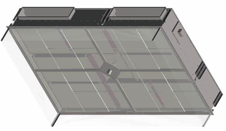
Unit series                                                                              Fresh Heaven MAXX O / POWER

Fresh Heaven MAXX O application field

                            The Fresh Heaven MAXX O series comprises low-turbulence flow units for pressurized
                            fields in operating theaters. The purpose of units is to prevent contamination of
                            operating zone through airborne particles by creating a protective zone of fully filtered
                            air around the patient.
                            Fresh Heaven MAXX O units control levels of contamination and safeguard full and
                            unidirectional air filtration across the entire outlet surface.
                            Low-turbulence flow units are intended for operating theaters with the highest require-
                            ments for uniform vertical air flow in hospitals complying with the local requirements
                            and standards.

Fresh Heaven MAXX O model range
                            Individual components are selected in the layout stage and meet customized require-
                            ments on site. Units are designed according to the requirements of DIN 1946-4 for
                            rooms of Class Ia.
                            For delivery - large-size units are divided into sections which are supplied separately
                            and connected together on site. Fresh Heaven MAXX O unit range in presented by two
                            unit series:
     Fresh Heaven MAXX O
                            Supply air is delivered by a central-plant air handling unit into the pressure chamber
                            and then filtered and delivered into the operating area.

     Fresh Heaven MAXX O
                  POWER
                            This unit design is based on the Fresh Heaven MAXX O version and is equipped with
                            a recirculating POWER module which sucks air within a room. Recirculated air from
                            the POWER module can be mixed with outside air supplied from central plant air-hand-
                            ling unit in the mixing chamber. This air flow is then delivered into the pressure cham-
                            ber, filtered and diffused into the operating area.

Parameter                   Fresh Heaven MAXX O                              Fresh Heaven MAXX O POWER

Air flow speed              0.18 - 0.38 m/s                                  0.25 - 0.38 m/s

                            1.83 m x 1.23 m (min.)                           2.40 m x 2.40 m (min.)
Dimensions                  3.20 m x 3.20 m (max.)                           3.20 m x 3.20 m (max.)

Number of model sizes       8                                                5

Central passage             For mounting surgical lighting                   For mounting surgical lighting

                                                                             Supplied by AHU (20-30% of total volume)
Operating mode/air supply   Supplied by AHU                                  and mixed with recirculated air

                            varnished steel sheet RAL 9010                   varnished steel sheet RAL 9010
Casing material             or stainless steel sheet V2A / AISI 304          or stainless steel sheet V2A / AISI 304

Filter seal                 Gel-type                                         Gel-type

                            Single-layer laminarizer or                      Single-layer laminarizer or
Outlets                     double-layer laminarizer (differential air flow) double-layer laminarizer (differential air flow)
                            PES fabric on aluminium frame                    PES fabric on aluminium frame

                            Tab. 1: Overview of basic unit parameters

4                                                                         FG-DC-2017-1046-GB • Subject to changes • R0-05/2018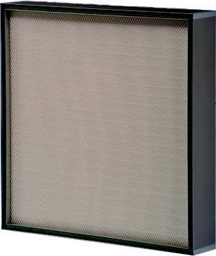
Fresh Heaven MAXX O / POWER                                                                                      Unit components

Unit components Fresh Heaven MAXX O and Fresh Heaven MAXX O POWER

                                                                               1

                                                                                                                              2

                                         8                                                                                             3

                                               7

                                                        6                             5                      4

                                                                               1                      16             9

                                                                                                                          10
                                                            13
                                                11

                                                                                                                                  15

                                                                                                                 4

                                                                                                         7

                                                                                                    12
                                                                                                                         17

                                                   14

                                    Fig. 1:        Overview of Fresh Heaven MAXX O and Fresh Heaven MAXX O POWER

                                    1:       Rectangular supply-air ducts                    10: PTI POWER module for circulating air
                                    2:       Power supply and differential pressure switch       (installed inside room)
                                    3:       Suspension points                               11: PU4 POWER module for circulating air
                                    4:       Central passage for lighting                    12: PCS POWER module for circulating air
                                    5:       Laminarizer                                     13: Mixing chamber
                                    6:       Soft wall                                       14: CGO unit for exhaust air
                                    7:       Pressure chamber                                15: Sound attenuator
                                    8:       HEPA filters                                    16: Extension air duct
                                    9:       PTE POWER module for circulating air            17: Suction air intake grille
                                             (installed outside room)

FG-DC-2017-1046-GB • Subject to changes • R0-05/2018                                                                                       5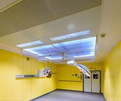
Fresh Heaven MAXX O                                                                          Fresh Heaven MAXX O / POWER

Fresh Heaven MAXX O

Functional description

                                                 1

    Extract air (ETA) Qe                                                   Outside air (ODA)

    Supply air (SUP) Qf                                                    Exhaust air Qe(EHA)

                      2                                                       2
                              3                                  3
                                        4                4
                                  5                              5                                          Power supply line
                                                 8                                                          230 V, 50 Hz

           7              9                                               9              7

                                                6

           7                                                                             7

                                  Fig. 2:   Fresh Heaven MAXX O functional scheme

Operating principle
                                  A central-plant air handling unit (1) supplies primary pre-treated air through rectangular
                                  air inlets (2). Pre-treated air is discharged into the pressure chamber (3) above a set
                                  of filters (4). The filters are fixed via clamps to a welded frame. Clean air, after filtering,
                                  flows out of a single or double-layer laminarizer (5) stretched across an aluminium
                                  frame into the operating theater (6) and forms the protection zone. Double-layer lami-
                                  narizer makes it possible to create differential air flow with a higher air speed within the
                                  area of surgical lighting.
                                  Contaminated air is then extracted from the room via extract-air grilles (7) into a central
                                  air handling unit (1). The unit design of Fresh Heaven MAXX O provides a space (8) in
                                  the centre to enable installation of surgical lighting.
                                  The circumference of the laminarizer is lit from above by LED lighting integrated into
                                  the sides of the casing. A PET-G soft wall (9) with an optional media bridge for supply
                                  connections may be installed around the unit.
                                  FHMO is not equipped with sound attenuating elements.

6                                                                             FG-DC-2017-1046-GB • Subject to changes • R0-05/2018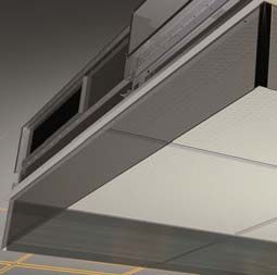
Fresh Heaven MAXX O / POWER                                                                            Fresh Heaven MAXX O

Unit sizes, variants and air flow range
                                     The Fresh Heaven MAXX O series comprise 8 unit sizes.
               Modular setup         Unit sizes A to F are combined of modules M1 and M2. These unit models comprise
                                     two M1 and two M2 modules. Unit sizes Y and Z can only include M1 module.
                                     Sample modular setup of Fresh Heaven MAXX O and overall unit sizes are presented
                                     as follows. Also refer to Fig. 4 for individual sizes and filter setup.
                     Air volume      Different air volumes are specified at three average air velocities of 0.24, 0.30 and 0.38
                                     m/s. Air volume is specified on the basis of the overall unit surface calculated by mul-
                                     tiplying unit nominal length by width.

                                                                       Module          Module      Inlet                           Weight
                            Air volume Air volume Air volume                                                    Max.
     Length Width      Area                                            M1 (2x)         M2 (2x)    length                Central     w/o
Size                     2  at 0.24 m/s at 0.30 m/s at 0.38 m/s                                                QTY of
     L (cm) W (cm)     (m )                                                                          IL                 passage    filters
                               (m3/h)      (m3/h)      (m3/h)                                                  inlets
                                                                      L1xW1 (cm)   L2xW2 (cm)       (cm)                            (kg)

A    320       320     10.2   8850        11060        14010      130 x 190        190 x 130     100       4            yes       280

B    300       300     9,0    7770        9720         12310      120 x 180        180 x 120     100       4            yes       230

C    300       240     7.2    6220        7780         9850       120 x 150        180 x 90      100       4            yes       200

D    300       200     6.0    5180        6480         8210       120 x 130        180 x 70      100       4            yes       190

E    240       240     5.8    4980        6220         7880       90 x 150         150 x 90      70        4            yes       170

F    240       180     4.3    3730        4670         5910       90 x 120         150 x 160     70        4            yes       150

                                                                  183 x 180
Y    183       180     3.3    2840        3560         4500       (1x)             -             100       2            no        130

                                                                  183 x 123
Z    183       123     2.2    1940        2430         3080       (1x)             -             100       1            no        110

                                     Tab. 2: Overview of data with 8 unit sizes and modules

                                                                              Cross section B-B

     B                                                                  B

                                                                              Cross section A-A
           A                                                      A

                                     Fig. 3:   Sample of Fresh Heaven MAXX O modular setup, bottom view and cross sections

FG-DC-2017-1046-GB • Subject to changes • R0-05/2018                                                                                         7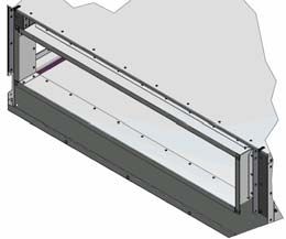
Fresh Heaven MAXX O                                                                Fresh Heaven MAXX O / POWER

             FEY

                                                                             FE4

                      Fig. 4:   Eight possible unit sizes, dimensions in mm and filter configuration

8                                                                 FG-DC-2017-1046-GB • Subject to changes • R0-05/2018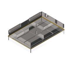
Fresh Heaven MAXX O / POWER                                                                    Fresh Heaven MAXX O

Air-supply connections
                                    The unit can be equipped with a maximum of 4 air-supply connections, which are
                                    located on the vertical panels of the casing. These connections are used for air ducts
                                    from the central-plant air-handling system.

Rigid connection
                                    As standard units are equipped with rigid connections. All dimensions are specified in
                                    mm.

                                    Fig. 5:   Fresh Heaven MAXX O rigid connection, side and face views

Limitations for supply connections
                                    Maximum 4 connections are possible. Maximum 2 connections can be blocked.
                                    FläktGroup recommends to use 2 symmetrical supply connections. Unused connec-
                                    tions are blocked. 4 air inlets are marked as I1, I2, I3 and I4.

                                                  D                            D                          D

                                              U                                 U                         U

                                    Fig. 6:   Limitations for air-supply connections

                                    • Consider the restrictions in the configuration of air-supply connections in the code
                                       when ordering the unit. A sample code is presented as follows.
                                    • For the complete designation of the unit code refer to “Unit Type Code” on page 23.

FG-DC-2017-1046-GB • Subject to changes • R0-05/2018                                                                     9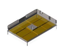
Fresh Heaven MAXX O                                                                  Fresh Heaven MAXX O / POWER

                                                                                                      Connections/inlets
                                                                                       Material       I1 I2 I3 I4
                            Order code              Outlet                                            R - rigid duct
                                                                      Unit version     2 - RAL9010
                            LxWxH (cm)               L/D                                              0 - blocked
                                                                                       3 - V2A        - stands for null
                                                                                                     inlets
                      FHM300x300x045           D                  O                    2             RRRR

                      FHM300x240x045           L                  O                    3             R0R0

                      FHM183x180x045           L                  O                    2             RR--

                      FHM183x123x045           L                  O                    2             R---

                      Tab. 3: Sample of partial code designation for units of different sizes

Control dampers
                      Each branch of the air-supplying duct must be equipped with air-flow control device.

10                                                                FG-DC-2017-1046-GB • Subject to changes • R0-05/2018
Fresh Heaven MAXX O / POWER Fresh Heaven MAXX O POWER
Fresh Heaven MAXX O POWER
Functional description
1
Extract air (ETA) Qe Outside air (ODA)
Supply air (SUP) Qf Exhaust air Qe(EHA)
Service room
AHU control panel
Power supply
3 4 5 5 4 3
230 VAC, 50 Hz
6 6
7 7
2 10 2
10 9
9 8
Communication cable 2.5 m (max. 10 m)
Control panel FHMO P
9 9
Fig. 7: Fresh Heaven MAXX O POWER functional scheme
Operating principle
Air flow from the air-handling unit (1) is mixed with the recirculated air (2) from the
POWER module (3) in the mixing chamber (4) and discharged into the pressure cham-
ber (5) above a set of filters (6).
After passing through full-area HEPA (H13/H14) filters (6) air creates a low-turbulent
displacement flow. The filters are fixed via clamps to a welded frame. Clean air, after
filtering, flows out of a single or double-layer laminarizer (7) stretched across an alumi-
nium frame into the operating theater (8) and forms the protection zone. This area
encompasses the operating and sterile instrument tables. Double-layer laminarizer
makes it possible to create differential air flow with a higher air speed within the area
of surgical lighting.
Smaller portion of polluted air is then extracted from the room via extract-air grilles (9)
into a central air handling unit.
Distribution of air flow
A central-plant air handling unit (1) supplies QF which is between 20-30% of the total
air volume. The required outside air flow rate is primarily determined by internal loads
and its minimum can depend on country regulations. Supply air is pre-treated in a cen-
tral air-handling unit, which is located outside an operating theater, and delivered to the
mixing chamber (4) of FHMO.Px units. There the supply air is mixed with pre-filtered
(F7) recirculated air portion QR, extracted from the operating theatre. FHMO.P units
are also equipped with flaps to avoid backflow through pre-filters in case of fan and
power failure. Part of the polluted air flow is then extracted and directed to the air-han-
dling unit (QEFresh Heaven MAXX O POWER Fresh Heaven MAXX O / POWER
QR regardless of clogging of filters with consideration of residual static pressure of
fans. To ensure the correct ratio and air-output velocity each outside-air duct must be
equipped with constant airflow regulators, which is not part of FHMO.P delivery.
The mixing ratio is preset to a constant value. To change the ratio the operator needs
to change air volume QF of AHU, recirculated air volume QR at the fans of FHMO.P
and the settings of air flow controllers (CAV) on inlet air ducts. The operator must
ensure that the total air volume Q100 remains unchanged.
Unit variants
The unit variants are performed as:
– Ceiling version where air intake for recirculating puproses is performed on the
ceiling level or in upper or lower wall corners
– Tower version where air intake for recirculating puproses is performed on the floor
level through rectangular vertical sections which are either installed in or outside the
operating theater
12 FG-DC-2017-1046-GB • Subject to changes • R0-05/2018Fresh Heaven MAXX O / POWER Fresh Heaven MAXX O POWER
Configurations for FHMO POWER units
The following table shows 6 unit configurations and their dimensions.
• For CGx and OT/OT+ panels refer to separate catalogs.
Configuration Top view Description
4 recirculation PU4 modules installed in false
ceiling.
Suction is performed through the grille on bot-
tom side of PU4
• Total length 5400 mm (size E) -
6200 mm (size A)
• Total width 2400 mm (size E) -
3200 mm (size A)
• Total height 450 mm
FHMO.PU4 Exhaust air ductwork not displayed.
28
0
Light fixtures not part of delivery.
4 recirculation PCB modules installed in false
ceiling.
Suction is performed through connecting ducts
(diameter 355 mm) on the back side of PCB con-
nected to e.g. CGx installed in false ceiling or
lower or upper wall corners.
• Minimum total length 4800 - 5600 mm
(without air ducts and CGx)
• Total width 2400 - 3200 mm
(without air ducts and CGx)
FHMO.PCB • Total height 450 mm (CGX in false ceiling
28
0
requires up to 600 mm)
Exhaust air ductwork not displayed.
4 recirculation PCS modules (2x L + 2x R)
installed in false ceiling.
Suction is performed through connecting ducts
(diameter 355 mm) on lateral sides of PCS con-
nected to e.g. CGx installed in false ceiling or
lower/upper corners (not part of delivery).
• Minimum total length 5200 – 6000 mm
(without air ducts and CGx)
• Total width 2400 - 3200 mm
(without air ducts and CGx)
FHMO.PCS • Total height 450 mm
28
0
(CGx in false ceiling requires up to 600 mm)
Exhaust air ductwork not displayed.
FG-DC-2017-1046-GB • Subject to changes • R0-05/2018 13Fresh Heaven MAXX O POWER Fresh Heaven MAXX O / POWER
Configuration Top view Description
4 recirculation PCU modules installed in false
ceiling. Suction is performed through OMF
grilles (above floor and optionally under ceiling)
connected to rectangular channels in OT/OT+
partition/facing (not part of delivery). Additional
attenuators (AA) and/or extension rectangular
air ducts (ED) may be needed to reach required
room dimension.
• Minimum total length 4800 - 5600 mm
(without AA or ED)
• Total width 2400 - 3200 mm
FHMO.PCU • Total height 450 mm
28
0
(without suction channels)
Exhaust air ductwork not part of delivery.
2 recirculation PTI towers installed in operating
room.
Suction is performed through grilles in towers
(above floor)
Extension air ducts (ED) and/or additional atten-
uators (AA) may be needed to reach required
room dimension.
• Minimum total length 4800 - 5600 mm
(without AA or ED)
• Total width 2400 - 3200 mm
FHMO.PTI • Total height according to false ceiling height
28
0
Exhaust air ductwork not part of delivery.
2 recirculation PTE towers installed outside op-
erating room (in the adjoining room).
Suction is performed through grilles in towers
(above floor).
Extension air ducts (ED) and/or additional atten-
uators (AA) may be needed to reach required
room dimension.
• Total length = room length + thicknesses of
walls + 1100
• Total width 2400 - 3200 mm
FHMO.PTE • Total height according to false ceiling height
28
0
Exhaust air ductwork not part of delivery.
14 FG-DC-2017-1046-GB • Subject to changes • R0-05/2018Fresh Heaven MAXX O / POWER Fresh Heaven MAXX O POWER
Sizes for FHMO POWER units
Size Separate outside-air inlets
A
FHMO-A.PU4
BCD
FHMO-B.PU4
E
FHMO-E.PU4
Tab. 4: Overview of FHMO.P sizes
Technical data
Electric Max. Electric Max.
100% Airflow at power Max. static electric Airflow at power Max. static electric
recirculation 0.30 m/s consumption pressure power 0.38 m/s consumption pressure power
at 200 PA consumption at 200 PA consumption
FHMO size m3/h kW Pa kW m3/h kW Pa kW
A 11059 1.5 560 3.4 14008 2.0 420 3.9
B 9720 1.4 500 3.3 12312 1.7 440 3.6
C 7776 1.1 550 3.0 9850 1.4 500 3.3
D 6480 0.9 600 2.9 8208 1.2 550 3.1
E 6221 0.9 620 2.9 7880 1.1 555 3.0
Tab. 5: Specifications for airflow, power consumption and pressure
Important note!
Minimum recirculated air volume Qr is 4400 m3/h.
Consider this when selecting FHMO size and outdoor air volume, especially for
smaller units.
FG-DC-2017-1046-GB • Subject to changes • R0-05/2018 15Description of components Fresh Heaven MAXX O / POWER
General description of components
Casing
– Used as a pressure chamber with 1 mm steel sides and top panels
– Can be performed in stainless steel V2A ~AISI 304 or varnished steel RAL 9010
– Joints are riveted and sealed with silicone
– Welded and sealed frame made of U/Z profiles
– Resistant to disinfectants and mechanical damage, easy to clean
– Independent suspension
– Probes for measuring pressure drop of filters and aerosol concentration
– Central passage 60 x 60 cm for mounting surgical lighting, the passage is sealed
with elastic sealant
– Casing height 450 mm
Laminarizer
– Single-layer polyester fabric (PES)
– Double-layer outlet using differential air flow with higher air velocity in the central
area of 100 x 200 cm
– Both types are performed with an aluminium frame
Components for Fresh Heaven MAXX O POWER
POWER module
POWER fan module (dimension in mm)
PU4 PCB PCS PCU PTE PTI
Height 450 450 450 450
Width 1200 1200 1200 1200 1200 1200
Length 1000 700 900 900 500 500
Rectangular For installation outside For installation
Round connector on bot- operating theatre (in ser- inside operating theatre (in
Round connec-
Note connector on tor on legt/right tom side vice room), height and service room), height
back side for Inwall air length of passage through according to the project,
D=355 mm side D=355 mm exhaust duct the wall: according to the front panels & grilles
project match wall facing
For improved acoustic features the chamber of the POWER fan module is lined with mineral wool slabs
Sound insulation
16 FG-DC-2017-1046-GB • Subject to changes • R0-05/2018Fresh Heaven MAXX O / POWER Description of components
Pre-filter for POWER module
– F7 filtration class
– Pre-filters not part of PCB, PCS and PCU configurations
Fans
– EC motors
– Automatic constant flow control (Constant Airflow, Total Airflow Control)
– Direct and indirect energy efficiency thanks to low power consumption during fan
operation and reduced heat load with reduced cooling demand
– 4x 230 VAC power supply voltage with 10 A circuit breaker
– 1x 230 VAC power supply voltage with 8 A type C circuit breaker
– Soft-start / soft-stop; tmax = 50 °C
– Zinc-coated steel spiral casing
Air-mixing module
Mixing module
(dimension in mm)
M4L/M4R (left/right)
Height 450
Width 1200
Length 500
Supply-air side inlet
400x200, preparation for
Note
PURO light fixtures
Sound attenuator (optional)
– Lacquered steel, lined with mineral wool slabs
– Sound attenuator is installed between FHMO inlet and POWER module
Junction duct (optional)
– Performed in galvanized steel
– Length is determined by the project requirements
Cooling assembly (optional for PTE and PTI)
– FHMO.PT can be equipped with an air-water heat exchanger
– If ordered, a mixing assembly with valves and software control is available. To avoid
formation of condensate, water temperature must be kept adequately higher than
dew point.
FG-DC-2017-1046-GB • Subject to changes • R0-05/2018 17Description of components Fresh Heaven MAXX O / POWER
HEPA filters
– Full area filtration with micro-fibreglass paper
– Individual filter plates are arranged in a V-shape
– 60 mm pleating height for H13 and 73 mm - for H14 filter class
– Gel seal for ease of installation and guaranteed tightness
– Frame performed in anodized aluminium, 104 mm high to assure stable form of fil-
ter plates
– Fitted with a protective grid on clean-air side
– Low initial pressure drop with recommended final drop at Δpmax=650
– Easy clamping and fixation
Filter availability When the Fresh Heaven MAXX O is ordered, filters are included and must not be
ordered separately. When filters need exchange, refer to the following tables for order-
ing data. The relationship between all unit sizes and filter sizes is presented in Fig. 4
where sample filter elements are abbreviated as FE.
Air volume and Air volume is specified at average velocity (Q0.38 m/s or Q0.30 m/s) at ground area cal-
pressure drop culated by multiplying unit nominal length and width. For each average velocity - initial
pressure drop (Δp) is specified as well.
Filter data H13
Size
Module
(refer
Marking
(refer
Number
Article Nr.
Filter size
Length/Width/
Q0.38 Δpi38 Q0.30 Δpi30 Filtration Weight
of filters [m3/h] [Pa] [m3/h] [Pa] area [m2] [kg]
to Fig. 3) to Fig. 4) Depth [mm]
A M1, M2 FE1 12 H13FEG-1167/A1BR2 1205/585/104 1167 110 922 87 27.7 10.1
B M1, M2 FE2 12 H13FEG-1026/A1BR2 1105/552/104 1026 110 810 87 24.0 9.0
C M1 FE3 4 H13FEG-1305/A1BR2 1105/690/104 1305 110 1030 87 30.1 10.6
C M2 FE4 4 H13FEG-1157/A1BR2 840/805/104 1157 110 914 87 26.7 9.4
D M1 FE5 4 H13FEG-1153/A1BR2 1105/590/104 1153 115 910 91 25.7 9.5
D M2 FE6 4 H13FEG-899/A1BR2 840/605/104 899 115 710 91 20.0 7.6
E M1, M2 FE7 8 H13FEG-985/A1BR2 805/690/104 985 115 778 91 21.8 8.1
F M1 FE8 4 H13FEG-820/A1BR2 805/540/104 820 130 647 103 17.1 6.8
F M2 FE9 4 H13FEG-657/A1BR2 690/505/104 657 130 519 103 13.7 5.6
Y FEY 4 H13FEG-1200/A1BR2 840/825/104 1127 105 890 82 27.3 9.5
Z FE2 3 H13FEG-1026/A1BR2 1105/552/104 1026 110 810 87 24.0 9.0
Filter data H14
Size
Module
(refer
Marking
(refer
Number
Article Nr.
Filter size
Length/Width/
Q0.38 Δpi38 Q0.30 Δpi30 Filtra-
tion area
Weight
of filters [m3/h] [Pa] [m3/h] [Pa] [kg]
to Fig. 3) to Fig. 4) Depth [mm] [m2]
A M1, M2 FE1 12 H14FEG-1167/A1BR2 1205/585/104 1167 100 922 79 29.0 11.1
B M1, M2 FE2 12 H14FEG-1026/A1BR2 1105/552/104 1026 100 810 79 25.0 9.9
C M1 FE3 4 H14FEG-1305/A1BR2 1105/690/104 1305 100 1030 79 31.4 11.6
C M2 FE4 4 H14FEG-1157/A1BR2 840/805/104 1157 100 914 79 27.8 10.3
D M1 FE5 4 H14FEG-1153/A1BR2 1105/590/104 1153 105 910 83 26.8 10.4
D M2 FE6 4 H14FEG-899/A1BR2 840/605/104 899 105 710 83 20.8 8.3
E M1, M2 FE7 8 H14FEG-985/A1BR2 805/690/104 985 105 778 83 22.8 8.8
F M1 FE8 4 H14FEG-820/A1BR2 805/540/104 820 120 647 95 17.8 7.4
F M2 FE9 4 H14FEG-657/A1BR2 690/505/104 657 120 519 95 14.2 6.1
Y FEY 4 H14FEG-1185/A1BR2 840/825/104 1127 95 890 75 28.5 10.5
Z FE2 3 H14FEG-1026/A1BR2 1105/552/104 1026 100 810 79 25.0 9.9
18 FG-DC-2017-1046-GB • Subject to changes • R0-05/2018Fresh Heaven MAXX O / POWER Controls and selectable components
Unit controls and selectable components (included in unit code)
Unit controls
Differential-pressure switch
– Monitors differential pressure of filters
– Pressure connection via two plastic tubes
– Switching capacity 1.5 A (0.4) /250 VAC
– Can be equipped with connections to a filter-exchange indicator or other optional
pressure-measuring devices
Filter-exchange indicator
– Can be mounted in the cental passage of the low-turbulence flow unit
– Signals filter clogging via red LED as optional feature
Control panel
Fresh Heaven MAXX O POWER recirculating units are controlled via Siemens Logo!
PLC with display. Basic functions are include:
– Switching units ON/OFF
– Switchover to economy mode
– Activation and deactivation of lighting
– Alarm function (fan failure, clogged HEPA filters or pre-filters)
Customers can use the MODBUS interface of a BMS to establish connection and
regulate a FHMO.P unit with a central-plant air handling unit.
Lighting
– Light-emitting diode (LED) lighting can be installed around the entire circumference
of the unit
– Economical, maintenance-free, long service life
– Safe voltage 12 VDC (+ power supply 230 VAC)
Color assignment
– FHMO "C" version (RGB+W): control (assignment and switching) of colors is done
by customer
– FHMOP "C" version: standard WHITE is used for day mode; RED for night
(reduced) mode; others settings can be performed on request
Soft wall
To minimize air turbulences, maximize laminar air-flow zone and prevent reduction in
its cross-section - a soft wall can be integrated on the entire circumference of the unit
– Performed as peripheral screen in PET-G
(polyethylene terephthalate glycol-modified)
– Standard width 30 cm
FG-DC-2017-1046-GB • Subject to changes • R0-05/2018 19Accessories Fresh Heaven MAXX O / POWER
Accessories not included in scope of supply (not part of unit code)
The following component are not included in the scope of supply for FHMP.O units and
must be ordered separately:
– CGF/CGG air outlets with HEPA filters for connection with PCS and PCB modules
– Air-extraction ducts for recirculation of air for FHMO.PCU unit versions
– Ducts for air exhaust
– Ducts for delivery of outside-air. Dimensions are site specific. Made-to-measure
adapters ensure correct position of all parts of the system.
– PURO light fixture 298x1198x110 / ZC254/M598LOS+GLASS IP54
• Customers can select various components from a range for air-extraction solutions
• Refer to separate catalogs on Clean Rooms - Wall Panels and Partitions, Clean
Rooms Ceilings and CGx Air Outlets/HEPA Filter Diffusers with detailed
specifications on:
– Exhaust panels RA/MA
– Exhaust channels for OT/OT+ panels
– OMS/OMN/OMF grilles
– CGx air outlets
Monitoring panel
– Can be optionally installed in a wall panel and enables the following functions:
– Temperature control
– Activation of two additional lighting switches
– Regulation of lighting intensity
– Clock with stop watch
– Display of data on supply connections, such as vacuum function, air pressure,
nitrous oxide and oxygen pressure
20 FG-DC-2017-1046-GB • Subject to changes • R0-05/2018Fresh Heaven MAXX O / POWER Project design instructions
Layout tips
Delivery
Fresh Heaven MAXX O components are packed in wooden/OSB crates and
cardboard boxes. Quantity and dimensions are provided on request. Laminarizer,
filter inserts and joining material are supplied is a separate packing.
Transportation
Unit may only be transported in its original packing. A fork lifter is used to lift the unit
components on a pallet and maneuver on site. If the site-installation space is limited, a
ladder is used and unit components are moved manually.
Dimensions and tolerances
The size of the unit is limited by structural, manufacturing and transport options and is
determined upon agreement between the manufacturer, designer and end user.
• Consider manufacturing and assembly tolerances when designing the dimensions of
the FHMO unit
• We recommend to keep a tolerance of 5 mm
Installation
The FHMO modules, mixing and recirculation modules are suspended on mounting
lugs using M8 threaded rods and special anchors.
• ensure to prepare M8 threaded rods in the concrete ceiling before suspension
• ensure access to outer sides of the unit
A sample installation sequence of low-turbulence flow casing components, operating
lamp pendant, filter inserts, laminarizer and soft wall screen is presented as follows:
FG-DC-2017-1046-GB • Subject to changes • R0-05/2018 21Project design instructions Fresh Heaven MAXX O / POWER
Operation manual
For detailed procedures and instruction on unit transportation, installation, commis-
sioning, operation and service
• refer to the operation manual “Laminar/Low-Turbulence Flow Units for Ceiling
Installation - Fresh Heaven MAXX - Fresh Heaven MAXX POWER”
• if required, contact your local FläktGroup sales office for any additional information
Ordering codes on page 23 indicate only the basic data for unit (type, dimensions and
features). When placing an order
• specify a range of parameters such as the filter class, mean air outlet speed, etc.
22 FG-DC-2017-1046-GB • Subject to changes • R0-05/2018Fresh Heaven MAXX O / POWER Unit type code Fresh Heaven MAXX O / POWER
R R R R
F H M 3 0 0 x 2 0 0 x 0 4 5 L O 2 S W M . P U4 _
I1 I2 I3 I4
Length L [cm]
Width W [cm of laminar field FHMO]
Height H [cm]
Diffusers/Laminarizer
R Perforated steel painted RAL9010
S Perforated steel, electropolished
L Single-layer PES (polyester) fabric
D Double-layer with differential airflow
O Operating theater, side inlets
Casing properties
2 Varnished steel RAL 9010
3 Stainless steel V2A ~AISI304
Air inlets I1, I2, I3, I4 (for FHMO.P only RRRR apply)
R Rigid connection
0 Blinded inlet
- Null inlets (types Y and Z don’t have inlets I2, I3, I4)
Pressure drop measurement and HEPA filter exchange signalling
0 without
P Differential pressure switch w/o LED signaling
S Differential pressure switch with LED signaling
Peripheral LED lighting
0 without
W white LED lighting
C RGB + white LED
Border soft wall as PET-G screen
0 without
M 300 mm-long transparent soft wall
. Air supply mode with active POWER module, applies only to FHMO.P
P Air-mixing chamber and fan module in RAL9010
U4 Suction from below (ceiling)
CB Backside connections for round duct
CU Connection for extract duct
CS Side connection for round duct
TE Tower installed in service room
TI Tower installed in operating theater
_ Standard (this code can describe unit)
! Atypical (specify in note)
FG-DC-2017-1046-GB • Subject to changes • R0-05/2018 23Notes Fresh Heaven MAXX O / POWER 24 FG-DC-2017-1046-GB • Subject to changes • R0-05/2018
Fresh Heaven MAXX O / POWER                            Notes

FG-DC-2017-1046-GB • Subject to changes • R0-05/2018      25
FG-DC-2017-1046-GB-Fresh Heaven MAXX O/POWER-DF-R0-2018-05 © Copyright 2018 FläktGroup
                                                                                                         FRESH HEAVEN
                                                                                   WWW.FLAKTGROUP.COM
                                                                                                        MAXX O / POWER

FläktGroup is the European market leader for smart and energy efficient Indoor Air
and Critical Air solutions to support every application area. We offer our customers
innovative technologies, high quality and outstanding performance supported by more
than a century of accumulated industry experience. The widest product range in the
market, and strong market presence in 65 countries worldwide, guarantee that we
are always by your side, ready to deliver Excellence in Solutions.

PRODUCT FUNCTIONS BY FLÄKTGROUP
Air Treatment | Air Movement | Air Diffusion | Air Distribution | Air Filtration
Air Management | Air Conditioning & Heating | Controls | Service

» Learn more on www.flaktgroup.com
  or contact one of our office
You can also read