Gen6 INSTALLATION INSTRUCTIONS - TITAN Fuel Tanks
←
→
Page content transcription
If your browser does not render page correctly, please read the page content below
TITAN pt. no.: 02 0000 0209

Important: Please read these instructions carefully and completely before
starting the installation.

                                  TITAN Fuel Tanks™
                         INSTALLATION INSTRUCTIONS

                              Gen6

           Extended Capacity Replacement Tanks for FORD Diesel Trucks

7020211 For 2011+ FORD truck models F250 & F350 : Crew Cab, Short Bed (6 ½ ft.)
7020311 For 2011+ F250, F350 & F450 (with pickup bed): Crew Cab, Long Bed (8 ft.)

Required Tools:                                  Recommended Optional Tools:

1 ea.   Ratcheting socket driver                 1 ea. Hydraulic transmission jack
1 ea.   13 mm socket                             1 ea. Vehicle hoist
1 ea.   12 inch long socket driver extension     1 ea. Impact wrench
1 ea.   13 mm end wrench
1 ea.   5/8 inch socket
1 ea.   9/16 end wrench
1 ea.   Medium flat blade screw driver
1 ea.   Large flat blade screw driver or punch
1 ea.   Needle nose pliers
1 ea.   Torque wrench handle for socket
1 ea.   Mallet or small hammer
1 ea.   Razor blade or sharp bladed
        knife.
Parts List:

1ea. Extra heavy-duty cross-linked polyethylene (XLHDPE) fuel tank for one of the
following Ford Motor Company diesel trucks:

               Crew Cab, Short Bed 2011
                     “Super Series”               Tank Identification: “FORD CCSB”

               Crew Cab, Long Bed 2011
                     “Super Series”               Tank Identification: “FORD CCLB,
                                                                        02 0000 0129”

Note: Each tank has an identification on its top. Please check to be
      sure the tank is properly identified as the one to fit your vehicle.

       1 ea. 02 0000 0197           TITAN Gen6 O-Ring (packaged in warranty envelope)

       1 ea. 02 0000 0112           ½” NPT x ¾” x 90 elbow (installed in top of
                                    tank by fill hose king nipple, extra in war. envelope)

       1 ea.   (See nos. below)   Rear tank strap, long strap (Short and Long Beds)
       1 ea.   (See nos. below)   Middle tank strap, intermediate strap (Long Bed only)
       1 ea.   (See nos. below)   Front tank strap, short strap (Short and Long Beds)
       3 ea.   99 0000 0103       Extruded Flexible Bushings (IF optional Titan Shield
                                  was ordered, the bushings are NOT included) 4 ea. for
                                  Long Bed.

       1 ea. 02 0118 0000 FORD, Front Tank Support Assembly, CC Short/Long Bed,
                           2011(Included complete in 22”x10”x4” box)

1 ea. 99 0102 0000 Roll Over Valve Vent Assembly with hose and vent cap.

Note: The Ford tank straps are identified by designations cut into the very bottom of the
      strap and/or on one side. These designations are:

                                      Crew Cab, Short Bed

       Rear Tank Strap:             1 ea.   02 0117 0000      Long Strap
       Front Tank Strap:            1 ea.   02 0117 0000      Short Strap

                                      Crew Cab, Long Bed
       Rear Tank Strap:            1 ea. 02 0121 0000         Long Strap: “3” or “R”++
       Middle Tank Strap:          1 ea. 02 0121 0000        Intermediate Strap: “2” or
                                                              “M”++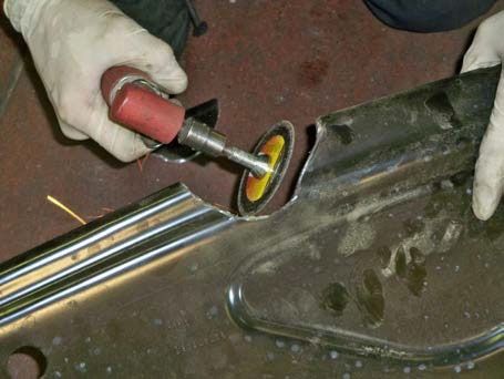
Front Tank Strap:             1 ea. 02 0121 0000        Short Strap: “1” or “F”++

++ The Long Bed straps will be stamped with a numeral or have a cut-out letter identifying their
position. This numeral or letter will be located on the in-board, vertical leg of the strap.

IMPORTANT NOTICE: Before installation, be sure to thoroughly inspect
inside of the tank for ANY foreign debris!
NOTE: TITAN 2011+ FORD Crew Cab, Short Bed and 2011+ FORD Crew Cab, Long
Bed products are extremely similar when it comes to installation procedures. Most of
the photos in these instructions show a Crew Cab Short Bed tank, but the procedures in
the pictures are the same for both.

Step Description

1      Using best, safe practices, place the vehicle on a hoist that leaves the entire
         underside of the frame unobstructed.
2      Drain all the fuel from the original equipment tank using a pump or siphon.
3      Remove original equipment tank plastic side shield and bottom shield (if
        applicable) from vehicle.
4      Disconnect the ¾” vent line hose and the larger fill hose from the fill spout,
        leaving them attached to the tank.
5      Disconnect fuel gauge electrical connection, feed line and return line from the
        sending unit.
6      Support the original equipment tank.
7      Loosen original equipment tank straps by undoing inside bolts first.
8      Remove the original equipment tank with its straps from the vehicle.
9      Remove original equipment “bumper bracket”, located to the right of the front
        strap, (See Fig. 1) from vehicle.
10     Make sure the wiring harness and differential breather hose (if applicable) are
        securely fastened to the vehicle frame as the new tank will need to be
        positioned next to the frame for its entire length.
11     Use a mallet and screw driver or punch to loosen the hold-down ring on the
        sending unit by tapping it and turning it counter-clockwise (See Fig. 2). Remove
        the sending unit from the original equipment tank. Do NOT reuse factory O-
        Ring seal. Save the factory hold-down ring for use on the new TITAN tank.
12     Remove fill hose and vent line hose from original equipment tank, they will be
        installed the same way on the new tank.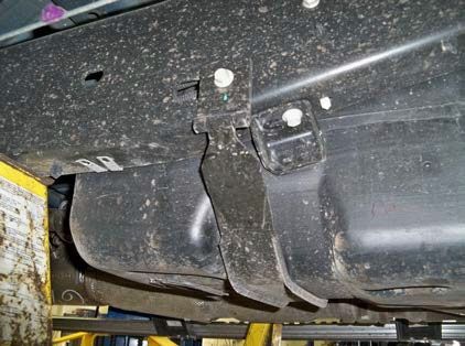
(Fig. 1) Remove original equipment strap and     (Fig. 2) Loosen hold-down ring on original
“bumper bracket”, shown here to the right-hand   equipment tank by tapping counter-clockwise,
side of the front strap.                         remove and lift out sending unit.

13     The new TITAN fuel tank comes with a new O-Ring to seal the sending unit. The
        O-Ring is packaged in the envelope with the warranty registration. Install
        the O-Ring as shown in Fig. 3.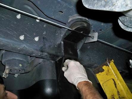
(Fig. 3) O-Ring gasket shown installed correctly.    (Fig. 4) Line the sending unit tab up with the
                                                     “Tab Location” markings on the tank.

14      Carefully place the sending unit into the new TITAN tank. Make sure the “O” ring
         gasket is placed properly under the sending unit to seal correctly. Before
         installing the sending unit into the TITAN Tank, BE SURE THE INSIDE OF THE
         TANK IS FREE OF DIRT OR DEBRIS OF ANY KIND.
15      After placing the sending unit into the tank on top of the “O” ring gasket, rotate it
         until the sending unit tab is lined up with the “Tab Location” markings on the
         tank’s top (See Fig. 4).
16      Place the factory (OEM) hold-down ring on top of the sending unit and use a
         hammer and punch, or screw driver to tap the ring clockwise until it is fully
         seated and locked (See Fig. 5).

(Fig. 5) Using a hammer and punch, or screw driver   (Fig. 6) Install fill and vent hoses from original
to tighten the hold-down ring clockwise.             equipment tank on TITAN tank as shown. Make
                                                     sure that ¾” vent line is lined up with orientation
                                                     mark on the tank.

17      Install the fill hose on the TITAN Tank King Nipple and the ¾” vent line hose on
          the ¾” elbow which is installed on top of the tank. Be sure all clamps are tight
          (See Fig. 6).
18      The TITAN tank straps will reuse the original equipment mounting bolts. Hang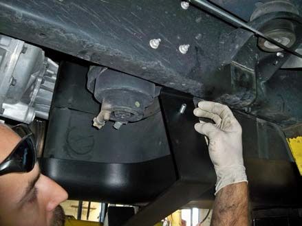
the outboard side of the straps first. The rear strap will attach to the underside
          of the frame and the front strap will attach to the outside. Start the stock bolt
          and make sure at least ½ of the thread is through. Leave the bolt loose. Note:
          The short bed tank comes with two straps, plus the front support bracket; the
          long bed tank comes with three straps, plus the front support bracket.
19      Place tank on a transmission jack. Lift the tank high enough to reconnect the
          sending unit electrical connection, as well as both the return, and feed lines.
          Line the straps up with the strap indentations in the tank.
20      Once all connections are securely attached, lift the tank the rest of the way into
          place with the jack.
21      Install the flexible bushings on both straps. Place it so it is centered in the
         bottom of the strap with the bushing’s channel side toward the strap. Press the
         bushings securely into place.
22      Attach the inboard sides of the straps. Tighten the bolt and bracket to
         factory specifications.
23      The “02 0118 0000 FORD, Front Tank Support Assembly” supports the front of
         the tank. It is made up of two major pieces: an upper and a lower. Hang the
         lower piece on the inside bottom lip of the vehicle’s frame. Slide it toward the
         rear of the vehicle until it lines up with the closest cab mount. Loosen the bolt
         from the cab mount and complete installation of the upper piece as shown in
         Figs. 7-12. If mounting the tank without a shield, be sure to place a flexible
         strap bushing on the load bearing surface of the lower piece under the tank.

(Fig. 7) Hang lower piece of support assembly           (Fig. 8) Place the supplied fender washer
on lower lip of vehicle frame and slide towards          into the center of the rubber cab mount above
the rear of vehicle until it lines up with cab mount.    the upper piece of the assembly.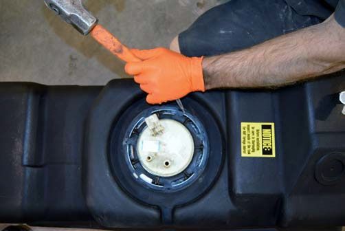
(Fig. 9) Mount the upper piece of the assembly to         (Fig. 10) Replace cab mount bolt with its existing
the lower piece using bolt provided.                      washers and tighten to factory specification.

     (Fig. 12) Installation of front support. Note the flexible bushings on the support and the straps.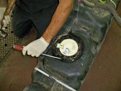
Installation Complete!

24     Attach the fill hose and the vent line hose to the vehicle’s fill spout as they were
        with the original equipment tank .
25     Make sure ALL mounting hardware, clamps, bolts, etc. are properly installed and
        TIGHT. Double check it.
26     Lower vehicle, fill tank completely with diesel fuel andcheck for
        leaks.                 IMPORTANT!

 Go to TITAN’s website to view video installation instructions and tips.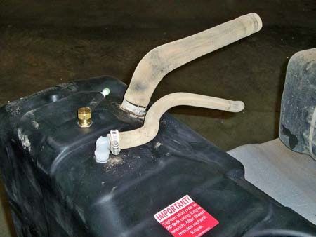
SPECIAL NOTE:
For 2011+ FORD truck models F250, F350 & F450 : Crew Cab
Short Bed or Crew Cab Long Bed
With FX4 Option Package
If the installation vehicle is equipped with Ford’s FX4 Option Package it will most likely
have a steel skid plate under the transmission and transfer case which may interfere
with the new TITAN fuel tank. If so, there are two courses of action: Remove and
dispose of the skid plate, OR “notch” the skid plate so as to allow the new TITAN tank to
fit with it.
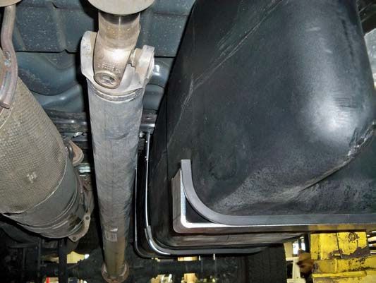
If you chose to notch the skid plate here are some suggestions:
A) If the skid plate interferes with the TITAN tank, loosen the skid plate, and detach
the driver’s side, before lifting the TITAN tank into place.
B) After the new TITAN tank is installed, hold the skid plate in place and mark it so
as to show where the notch for the new tank needs to be located. The “notch” does not
necessarily need to follow the contour of the front of the tank as illustrated below. It can
be circular, triangular, or rectangular and the skid plate will still function fine. The notch
can even be two parallel cuts made with a hack saw and the resulting flap bent up out of
the way over the plate to form the “notch”. One important thing is to be sure the
closest point on the “notch” is at least ½ inch (13 mm) away from the tank.
C) The skid plate may be cut with a grinding wheel, Sawzall, hack saw or other
suitable tool. Be sure to smooth the edges and touch up the exposed metal with paint.
D) Reinstall the skid plate and adjust to its lowest level on the passenger side.
See photos below.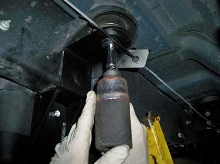
Be sure to return the completed warranty registration for your new Titan fuel tank; or you
                      can register on-line at www.titanfueltanks.com

You will find your tank’s serial number located approximately ½ way up the driver’s side
            located towards the rear of the tank; adjacent to the sending unit.

Write your tank’s Serial Number here:
 A tank must be registered within sixty (60) days of receipt for the warranty to be valid.

                   Warranty is void if product is improperly installed.
          For questions or customer service call (800) 728-4982

                                TITAN Fuel Tanks™
                                   P.O. Box 2225
                           Idaho Falls, ID 83403 USA
                  Telephone (208) 522-1325, FAX (208) 529-2162
                             www.titanfueltanks.com

                TITAN Fuel Tanks are PROUDLY MADE IN THE USA!

              Revised 06.04.2021     ©2021 Supertanks, LLC. All rights reserved.
You can also read