General Catalog UNDERWATER SCIENCE PRODUCTS - TECHNOLOGY FOR SUSTAINABLE FISHERIES
←
→
Page content transcription
If your browser does not render page correctly, please read the page content below
General Catalog
UNDERWATER SCIENCE
PRODUCTS

          TECHNOLOGY FOR SUSTAINABLE FISHERIES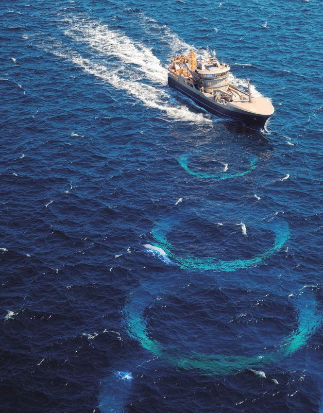
TRANSDUCERS
Transducers are the core of all SIMRAD
products. The ability to efficiently convert
the digital signal to sound in water, and
vice versa, is of great importance of any
acoustic system. Because of this SIMRAD
design and produce our own transducers
in order to secure the best performance
in all our products.

OMNIDIRECTIONAL SONARS                                        ECHO SOUNDERS
In SIMRAD omnidirectional sonars up to 480 elements           A good transducer makes a good echo sounder. SIMRAD produces
are used to create multiple beams, covering 360°              a variety of transducers with centre frequencies spanning from
horizontally and 180° vertically. All elements are designed   12 kHz to 333 kHz, and most of these come in a split beam
and produced in-house, thus the production of a single        configuration with multiple receiving channels. SIMRAD uses
transducer will take several days.                            only ceramics and composite material in our transducers and the
                                                              production is done using the latest in ceramic cutting machines and
                                                              production facility.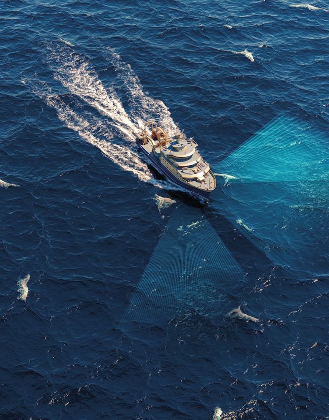
EK80 ADCP
The SIMRAD EK80 ADCP uses a phased
transducer array to produce 4 narrow acoustic
beams that can be used to calculate current
velocities by measuring the doppler effect. The
phased array can also produce a narrow echo
sounder split beam using the same transducer.

WIRELESS SYSTEMS
Wireless trawl sensors communicate acoustically
to the vessel and between sensors. To be able
to do this a transducer is needed to convert
electrical signals into acoustic signals and
vice versa. Small transducers in various
frequencies are then placed inside the net
sensor. Also, under the vessel a hydrophone
is placed to be able to communicate with the
sensor. A hydrophone is only listening, it is not
transmitting.

3RD WIRE SYSTEMS
A 3rd wire system gives you real time information
from the trawl. Along with other sensors, the trawl
sonar is scanning the opening of the net, providing
information of fish entry and trawl behaviour. Of
course, it also has a SIMRAD transducer inside!

MULTIBEAM SYSTEMS
A scientific multibeam transducer consists of 800
individual elements that create configurations of multiple
beams based on the user requirements. Combined
elements are used to form beams in the shape of a FAN or
MATRIX, allowing for real time 3D and 4D information to
be collected.


CONTENTS
SIMRAD: Innovation, values and history            4

TRANSDUCERS                                      10

TD50 SOFTWARE                                    14

SINGLE BEAM SYSTEMS                              18
       EK Systems                                20
       EK80 Software                             22
       EK Mission Planner                        24
       Calibration                               26
       Specifications                            27

EK80 ADCP                                        30
       Specifications                            32

MULTIBEAM SYSTEMS                                34
       ME70                                      36
       MS70                                      40
       Specifications                            42

SONARS                                           44
       ST90                                      46
       SU90                                      47
       SX90                                      48
       CS90                                      49
       SN90                                      50
       Specifications                            54

CATCH MONITORING SYSTEMS		                       60
       Receivers                                 62
       PX Sensors Family                         64
       PX TrawlEye                               66
       PX Flow Sensor                            67
       TV Software                               68
       FS Sonar                                  69
       FM Sonar                                  70
       FX System                                 72
       Sensor location and available functions   74
       Specifications                            76

SUPPORT SERVICE			                               80
4 SIMRAD Innovation, values and history

SIMRAD
MORE THAN 70 YEARS
OF INNOVATION
Since SIMRAD introduced the sonar technology
to the commercial fishery in Norway in the 1950s,
the products have always evolved around sound in
water. Through a close connection with the scientific
community, important developments such as
instruments for quantification of biomass, fish size
estimation and tools for species identification has
been commercialized and introduced to scientists
worldwide.

SIMRAD's slogan is “Technology for sustainable
fisheries” and we live by this slogan every day.
We believe that a sustainable fishery is dependent
on accurate tools to quantify and understand the
marine ecosystem, and the SIMRAD products have
always been in the forefront on providing for this.

Sustainability in this context also involves the
environment, and all SIMRAD products are designed
to facilitate efficient surveys. Scientific Multibeam
Systems are used to increase sampling volume with
less ship time needed to achieve the survey goal.
Trawl monitoring systems are used to monitor trawl
behaviour, as we believe optimal trawl performance
also leads to reduced fuel consumption, less impact
on the fauna and the right species and the right
amount in the catch.

Following the current mantra in management and
research communities, SIMRAD now offers products
for ecosystem monitoring, ranging from small
plankton to large mammals. As the focus shifts
from single fish stock management towards looking
at the whole food web, SIMRAD shall continue to
develop new and refine existing tools for mapping
the marine ecosystem.

                                                        Innovation, values and history SIMRAD   5
PHILOSOPHY AND VALUES
                                            All SIMRAD products shall reflect our set of common
                                            values. One of our core values is innovative and this
A tool must work                            is the basic of the SIMRAD soul. We always strive
                                            to find new ways to make your life at sea easier
every time you                              by refining the tools you use. After more than 70
need it and this                            years in the business we still come up with new and
                                            refined products.
is the foundation
of our design                               A collaborative and reliable partner is always
                                            important for any projects. Even more so when you
work. We know,                              work at sea or in remote areas. Regardless of the
after more than                             environment you operate in you shall never be in
                                            doubt that your SIMRAD equipment will perform.
70 years in the
same business,                              Determined we shall continue to refine existing
                                            products and come up with new ones. All with the
what it takes to                            same goal; to improve the acoustic tools available
make a reliable,                            for our valued users.

high performance
affordable tool for
the scientist.

6   SIMRAD Innovation, values and history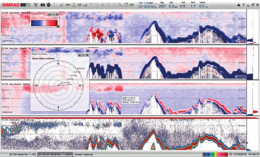
DETERMINED
We are known for our drive and persistence. We always strive to
meet our customers' expectations. We set ambitious goals for
ourselves and we are driven towards them with a clear and constant
focus.

WHAT WE START, WE FINISH. WE DO NOT GIVE IN.

                                                                     INNOVATIVE
                                                                     Always performing better is a vital part of who we are. We
                                                                     constantly innovate and implement improvements in all parts of
                                                                     our business - from our products, through our processes, to our
                                                                     customers' experiences.

                                                                     WE RELENTLESSLY PURSUE IMPROVEMENTS, NEW IDEAS AND
                                                                     NEW SOLUTIONS.

                                              RELIABLE
                                              Our customers and partners can trust SIMRAD to deliver, always.
                                              Dealing with SIMRAD means dealing with reliable people, a reliable
                                              corporation and reliable products. SIMRAD is a responsible
                                              organization characterized by integrity and concern for health,
                                              safety and the environment.

                                              WE ARE RELIABLE PEOPLE. WE ARE RESPONSIBLE CITIZENS.

                                                                     COLLABORATIVE
                                                                     Collaboration is fundamental to our business. We exchange
                                                                     ideas among ourselves, with our suppliers and partners, and we
                                                                     cooperate closely with our customers. We work as teams, we
                                                                     share knowledge and we value team success - to the benefit of our
                                                                     customers and our own competitiveness.

                                                                     WE COLLABORATE AS INDIVIDUALS AND AS AN ORGANIZATION.

                                                                                                         Innovation, values and history SIMRAD   7
The SIMRAD brand name is owned by the                                 Today KM manufactures a great variety of
                                                     Kongsberg Group, a Norwegian technology                               products, such as acoustic systems for mapping
                                                     company. The Kongsberg Group has a strong                             and positioning purposes, AUVs (Autonomous
                                                     position in the maritime sector through its company                   Underwater Vehicles), dynamic positioning,
                                                     Kongsberg Maritime (KM), where the SIMRAD                             MRUs (Motion Reference Units), high accuracy GPS
                                                     branded products are sold.                                            positioning systems, Engine control systems, Bridge
                                                                                                                           Navigation systems as well as all the SIMRAD
                                                                                                                           products.

                                                   1950

                                                          1951                             1960                                          1970
                                                          • First SIMRAD Echo sounder

                                                          1958                                    1968                                          1970
                                                          • First fishery research sonar          • First generation EK scientific              • Rack version of EK sounder,
    1940
                                                            and echo sounder,                       echo sounders with calibrated                 EK-S and the first analogue
                                                            Simrad 580-10                           output at 12,18, 38 and 120 kHz               Echo integrator Simrad QM

           1947
           SIMRAD foundation

    1950                                           1960                                    1970                                          1980

8          SIMRAD Innovation, values and history
HISTORY
SIMRAD was founded in 1947 by
Mr. Willy Simonsen. The name
SIMRAD derives from “SIMonsen
RADio” and, as the name indicates,
it all started with radios. But
this shortly developed into echo
sounders and sonars. Today
SIMRAD is recognized all over the
world for premium performance
products and manufactures sonars,
echo sounders and net monitoring
equipments.
2010
2000
2013
• RAW data output on omni
1980 directional sonars
• EK400 and digital echo
integrator Simrad QD
2015
2002 • Simrad EK80, first scientific
• First composite transducer wideband echo sounder
1984 2003
• Simrad ES400 First 2016
• EK60 introduced with BI60 post • WBAT, first wideband
split beam
processing software, computer style, autonomous echo sounder
echo sounder
with frequencies 12 to 400 kHz
1989 2017
• SIMRAD EK500. 2005 • TD50, first real time
First echo sounder • Simrad ME70, first scientific 3D visualization software
with high instantaneous multibeam echo sounder
dynamic range
2019
2006 • CS90 first broadband sonar
• Simrad MS70, first scientific • First Simrad EK80 ADCP
multibeam sonar
2010 2020
Innovation, values and history SIMRAD 9
1980 1990TRANSDUCERS
SIMRAD is one of the
very few producers
of transducers.
The transducer is an
important part of
an echo sounder's
performance.
A transducer is the
combination of a
microphone and a
loudspeaker, all in
one. The transducer is
converting electrical
energy into sound waves
and vice versa. What you
see on the echo sounder
screen is actually echoes
from transmitted sound.
10 SIMRAD TransducersFROM ELECTRICITY
TO SOUND
The transducers' ability to convert electrical
energy into sound depends on how it is built.
The more efficient it converts, the better the
transducer is. There are several ways to make
a transducer with different materials that can be
used. Today, ceramic is the best material to use
seen from a performance view. Other materials
such as nickel or ferrite have a lower price but
will not convert electrical energy as efficient as
the more costly ceramic material. The way the
material has been used in the production also
matters to the final performance. The latest
on the scene is to produce the transducers
using composite technology, which is a special
way of designing a ceramic transducer. The
advantages are that the transducer has an
efficiency of up to 75%, meaning if you put
1000W into the transducer 750W comes out
into the water. The same conversion is valid
when the signal comes back and it is vital for
detection of weak targets even when using low
powered transceivers.
The transducer also needs to be designed
in a way that avoids ringing. Unlike a church
bell that continues to ring after a strike, the
transducer needs to shut off immediately
after one ping in order not to disturb the next
ping. SIMRAD's design and choice of material
ensures a ring free transducer.
Transducers SIMRAD 11SPLIT BEAM, WIDEBAND AND DEPTH
RATED TRANSDUCERS
SIMRAD transducers are designed to work optimally
across a large bandwidth and in demanding environments.
We can divide the features of the transducers into three
main categories:
"We are at the forefront
of performance through
innovative design and
SPLIT BEAM TRANSDUCERS
a unique production
A Split Beam transducer is made to send out patterns, and in the end you can record calibrated
technology" one beam and receives the echo in three or four target tracks within the acoustic beam. SIMRAD
channels. Variations in phase of the returned echo commercialized this technology in the 1980’s and
KJELL GJESTAD enable us to locate the target within the acoustic our EK split beam echo sounders are now used
Value Chain Manager beam. Once you know the location of a target you to record data for marine resource management
can make up for variations in the beam worldwide.
COMMONLY USED SPLIT BEAM TRANSDUCERS
MODEL PART NUMBER NOMINAL FREQUENCY NOMINAL OPENING ANGLE MATERIAL
ES18 KSV-088694 18 kHz 11° Ceramic
ES38-7 321842 38 kHz 7° Ceramic
ES70-7C KSV-203678 70 kHz 7° Composite
ES120-7C KSV-204580 120 kHz 7° Composite
ES200-7C KSV-203003 200 kHz 7° Composite
ES333-7C 322598 333 kHz 7° Composite
WIDEBAND TRANSDUCERS
A Wideband transducer can transmit and receive on When the Simrad wideband transducer is combined
a wide frequency range, for example 45-90, 90-170 with Simrad wideband transceiver it is possible to
or 160 to 260. This means that with 3 transducers make sweep transmissions where the frequency
you cover a frequency range from 45 to 260 kHz. continuously increases throughout the transmitted
To make a transducer that is capable of doing this, pulse - also known as a chirp. It is also possible to
composite technology is our preferred production transmit on several discrete frequencies, one at a
technique. While composite transducers have the time. Advanced users may define an arbitrary signal,
highest bandwidth, some tonpilz transducers might such as a dolphin’s click. This opens up a whole new
still have some bandwidth available as seen in the world in interpretation of the echo, taking a great
ES38-7 in the table below. step forward towards the goal of providing a species
identification echo sounder, or “ecosounder”.
COMMONLY USED WIDEBAND TRANSDUCERS
MODEL PART NUMBER FREQUENCY NOMINAL OPENING ANGLE MATERIAL
ES38-7 321842 35 to 45 kHz 7° Ceramic
ES70-7C KSV-203678 50 - 90 kHz 7° Composite
ES120-7C KSV-204580 85 - 170 kHz 7° Composite
ES200-7C KSV-203003 160 - 300 kHz 7° Composite
ES333-7C 322598 250 - 500 kHz 7° Composite
12 SIMRAD TransducersDE TH RATED TRANSDUCERS
Sometimes collecting data from a vessel simply depth rated transducers have standard depth
does not do the job for you. Perhaps you need to rating to 1500 meters, but should you for some
get the transducer closer to the target for better reason need to go deeper feel free to contact us.
resolution, or perhaps you want to deploy echo
sounders in the deep for long term collection of A new range of compact depth rated transducers
data. SIMRAD has for many years built (model name ending in DK) has been developed for
transducers for applications like this. Our series of platforms where size is an important factor.
DE TH RATED TRANSDUCERS
MODEL PART NUMBER NOMINAL FREQUENCY NOMINAL OPENING ANGLE MATERIAL
ES38-DD S 11 8 Hz ° Ceramic
ES70-7CD 0 0 Hz ° Composite
ES70-18CD 1 0 Hz 18° Composite
ES120-7CD 4410 1 0 Hz ° Composite
ES200-7CD S 0 1 4 00 Hz ° Composite
ES333-7CD 1 0 Hz ° Composite
ES38-18DK 1 4 1 8 Hz 18 Ceramic
ES200-7CDK 40110 41881 00 Hz Composite
ES333-7CDK 401 04 41881 Hz Composite
* Standard depth rating: 1500 meters. Other depth rated transducers available on request.
** Split beam version / Single beam version
DID OU NO ...
The physical dimensions of a transducer can be traditional Simrad research transducers are given,
explained as a function of the beam opening at a where the maximum and minimum source level (SL)
given operating frequency. Traditionally 7° opening is calculated from the available power settings on
angle has been the standard for marine surveys, the Simrad EK 0 echo sounder and the near field
but for applications where size and weight is of is calculated by the formula:
great importance you can reduce the size of the
transducer by allowing a larger opening angle of
the acoustic beam. The effective transducer face
circular area is calculated from the general formula:
Where
A effective transducer circular area
=wavelength
ß =beamwidth in radians (-3 dB points)
In the table below some parameters from the
EFFECTIVE TRANSDUCER TRANSDUCER NEAR
FREQUENCY WAVELENGTH BEAMWIDTH MAX/MIN SL
CIRCULAR AREA FIELD
18 kHz 8 mm 11° 1 d 14 cm 1 8 cm
38 kHz mm ° 1 d 8 0 cm 08 cm
70 kHz 1 mm ° 1 d 4 cm 11 cm
120 kHz 1 mm ° 1 d 8 cm cm
200 kHz 8 mm ° 0 1 d 0 cm cm
333 kHz mm ° 1 0 d 11 cm 4 cm
Transducers SIMRAD 13SIMRAD TD50
3D VISUALIZATION SOFTWARE
The Simrad TD50 enables live streaming of 3D data accurate 3D visualisation is delivered in real-time, the
generated by scientific multibeam systems. The benefits are significant.
Simrad TD50 software reads the incredibly clean
raw data from the ME70 and MS70 in real time, and The TD50 provides researchers and vessel crew with
delivers accurate live visualisation of the oceanspace a highly effective decision tool, allowing for informed
beneath the vessel to the scientific lab as well as decisions to be taken immediately.
any other location onboard wtih network access.
Previously this data had to be post-processed before The TD50 also visualizes single beam EK80 echo
the 3D potential of the system was realised. sounder data and the current profile measured by the
ADCP in the same georeferenced framework.
Accurate 3D visualisation gives users a better
understanding of the marine ecosystem by i.e. The system is especially relevant to projects using
enabling precise measurement of schools of fish adaptive sampling, as the live 3D stream of the
rather than estimating size and shapes based on survey area enables researchers to see specific
models. Additionally, 3D view of bottom topography attributes as the vessel passes over them, allowing
and the relating bottom habitats further enhances action for further inspection to be taken immediately.
the understanding of the marine ecosystems. When
SITUATIONAL
AWARENESS
The live 3D stream can be delivered to
multiple locations on board which allows for
better interaction between scientists and the
vessel operators. This is typically important
in demanding operations where the vessel
interacts with objects in the water column.
Research vessels engaged in active sampling
of biology such as trawling can also impro-
ve their capabilities, with the Simrad TD50
system effectively providing a 'long range
camera' below the surface.
14 SIMRAD | TD SoftwareThe Simrad TD50 3D Visualisation Software is shown presenting sand eels on sand bottom. The raw data is taken from the
Simrad ME70 Scientific multibeam echo sounder on M/S Simrad Echo.
The TD50 can also import and display a chart overlay. This picture shows TD50 with MS70 data, Vessel, a school of fish and
bottom backscatter is shown to give full situational awareness.
TD Software | SIMRAD 15SINGLE BEAM SYSTEMS EK80 ADCP MULTIBEAM SYSTEMS SONARS CATCH MONITORING SYSTEMS
"The new wideband
echo sounders provide significant
information about some of the
basic backscattering properties
of a target, which leads to
improve target characterization."

LARS NONBOE ANDERSEN
Product Manager
Underwater Science
SINGLE BEAM SYSTEMS
SINGLE BEAM
SYSTEMS
The foundation of any survey
Calibrated split beam echo sounders operating at multiple frequencies are the basis of
any quantitative survey. The first SIMRAD EK echo sounders with calibrated output were
introduced in 1968. Since then, the equipment and techniques have evolved but the
basic of multifrequency remains the same.

Through the introduction of scientific echo sounders capable of transmitting sound
pulses with variable frequency, SIMRAD now takes research to the next level. These
sounders can be used as narrowband (CW) in some situations, and as wideband in
other.

We envision the EK scientific echo sounders to be the basic research tool for any
underwater science application, a system that can be adapted to match any situation
and any environment.
SIMRAD EK SYSTEMS

EK is our common name for all single beam echo                  layers, and those times it is good to know that the
sounders designed for research applications. The first EK       sounders use the same currency. Simrad RAW data is an
sounder was introduced in the 1960’s, and already back          open, well documented format, as can be expected from
then the focus was to create a quantitative sounder that        a scientific system.
could measure biomass.

Recently, the EK system has been used for a wider range
of oceanographic applications, with the addition of ADCP
functionality completing the picture.

All EK echo sounders share some common features such
as built-in calibration and split beam capabilities with full
beam compensation for accurate TS measurements. The
focus when designing the EK echo sounders is that you
should be in full control of all sounder parameters. That
is why there are no automated settings in the acquisition
SW. A skipper might want optimal settings displayed at
all times to get a good picture of the fish, but a sudden
change in ping rate or duration might corrupt a survey,
with data no longer comparable.

Another common feature is a standardized data format,
which means that you can compare data across                      In this EK80 screen capture you see hard bottom in deep red colour,
platforms. In many cases you need to combine your vessel          herring schools releasing gas that slowly drifts towards the surface and a
data with data collected from profiling platforms to get TS       substantial layer of plankton and small jelly fishes.
measurements or measurements from deep scattering

     EK is our
     common name
     for scientific echo
     sounders and
     current velocity
     profilers (ADCPs)
     for research
     applications

20    Single Beam Systems | EK Systems
WIDEBAND ECHO SOUNDERS
The new series of EKs has wideband capabilities. for such environments. The EK80 is prepared for
That means that you can transmit a signal that such requirements, and as the SW continues to be
varies across the transmission, called a chirp. The developed, new functions would be available.
most common way to operate the sounder is to use
a linear chirp. In an EK80 chirp you either utilize the
entire effective frequency band of the transducer, or
you can choose to limit the bandwidth.
Due to advanced matched filtering techniques you
can correlate the returned signal with what you sent
out, and the result is improved range resolution of
single targets. Also, as resolution is now a function
of bandwidth rather than pulse length, chirp allows
for long range performance without scarifying the
SINGLE BEAM SYSTEMS
resolution. When you have very weak targets in the
near vicinity of strong ones, such as small fish close
to bottom, you might want to use a different pulse
shape. A dolphin’s click is shorter, but still spans
over a large bandwidth and might be better suited
Range resolution and target ID are improved. Echo from a 38,1mm tungsten sphere is measured, and you can clearly see how the target
strength changes with frequency. This frequency response is unique to this particular target, and corresponds well with the theoretical
curves. Resolution is excellent, and you can clearly see the knot on the fishing line where the suspended sphere is attached to the line,
around 10cm from the sphere itself.
EK Systems | Single Beam Systems 21EK80 SOFTWARE
The traditional Simrad EK80 system consists of an The EK80 SW is the command and storage centre of the
acquisition software, one or more wideband transceivers, system. This is where the user sets the parameters of the
and transducers. When used with the EK80 real time transmission and the data you want to record. The EK80
acquisition software, the system is operated by a also has advanced tools for replaying and visualization
WindowsTM based processor. Also, the system normaly of data. Biomass in predefined layers is automatically
requires input from auxiliary sensors such as GPS and calculated, and the SW has lots of new tools such as
motion sensor. frequency response across the frequency band and a neat
little zoom tool that can be used to inspect details.
1
2
3
2
1
Frequently used buttons and numerical displays such as ship heading, roll, pitch and
heave are always shown on top of the EK80 SW. The EK80 has new tools that can
be used to inspect and display data, when clicking on the magnifying glass you would
for instance get access to a zoom tool that can come in handy when creating screen
shots to use as examples.
3
All settings needed to operate the EK80 The SETUP menu includes installation
SW are distributed under five main tabs and calibration settings
for easy operation: The ACTIVE menu contains settings
and calculations for the active channel or TS response for resolved targets is calculated
The OPERATION menu is the place layer. Layer definition, biomass calculation and displayed as a function of frequency
where you have all settings that are parameters and TVG settings are all set in real time in the EK80 SW. In this capture
directly influencing the RAW data you up here. you can see three objects passing the single
record, such as transmission settings and The EXTRAS menu, which is displayed target criteria, all being picked out of a dense
settings related to RAW data recording. here, shows numerical details from the mackerel school at 81, 91 and 98 meter
The DISPLAY menu comprises settings transmission, as well as the results from range. In the tool menu you can also set the
that regulate how the SW appears on your the active layer. parameters of what is to be recognized as
computer right now. single targets.
22 Single Beam Systems | EK80 SoftwareWIDEBAND TRANSCEIVER (WBT)
The Wideband Transceiver is designed for applications where
performance is the top priority. The WBT has four 500 W channels that
can either work independently with single beam transducers, or together
with a split beam transducer. The WBT is optimized for applications
where power consumption and size is not critical, typically on board a
research vessel or a platform with power and and high speed
Ethernet communication available.
The WBT transceiver is capable of operating on entire band from
10 kHz to 500 kHz, only limited by the transducer's bandwidth.
WBT MINI
SINGLE BEAM SYSTEMS
As a compact version of the Wide Band Transceiver, the WBT Mini presents an
energy e cient and splash proof design. The frequency range (30 500 kHz) and
the output power are lower than in the WBT. In return it offers very low power
consumption, perfect for platforms with limited available power and space.
The WBT Mini also has built-in multiplexing on each transceiver channel,
allowing for alternation between two 4 channel split beam transducers, or a
combination of 3 channel split beam and single beam transducers.
WBT TUBE
The WBT Tube is a 4000 meter depth rated
version of the EK 0 WBT family. The tube
contains two built-in transceivers that rely on
external power. It is connected to the EK 0
processor through Ethernet.
EK 0 PORTABLE
The EK 0 Portable system has all the tools needed for your
survey but in a small size. The EK 0 software runs on an
internal processor with built-in GPS, all controllable from
your phone or tablet through WIFI connection. The WBT mini
transceiver allows for a compact, energy effective solution, with
up to two selectable transducers connected at the same time.
EK80 Software | Single Beam Systems 23PLAN YOUR MISSION
The EK80 Mission Planner is, as the name implies, a After carefully planning the deployment, all settings
software used to plan a mission from deployment to are uploaded to the transceiver. The unit is then ready
recovery. to be deployed, and the only remaining task is to click
on the Activate mission button.
All details regarding when the sounder should wake
up, how long it should transmit and when it should go Apart from uploading the setup for a predefined
to sleep can be set before deployment. mission, the settings created in the Mission Planners
can be used in an “interactive mode” that allows the
In the Mission Planner the user can set as many user to redefine some of the parameters even after
phases as the survey requires. This could be helpful the deployment.
if you want the transmission scheme to change
throughout the deployment. You might want to do
CW most of the time, while doing chirp in shorter
periods to look at frequency response of targets.
1
2
3 4
1 2 3 4
PING GROUP LIBRARY PHASE(S) ENSEMBLES PING GROUPS
The ping group library The Phase defines when and An Ensemble is a collection of A Ping Group defines ping
contains a collection of your how often the transceiver should one or more Ping Groups from parameters, such as its
personal ping groups defining wake up during a deployment the Ping Group Library. Within frequency, power, pulse type
what the transceiver will do period. A mission plan must an Ensemble, it is possible to and pulse length.
when it wakes up. contain at least one phase. choose several Ping Groups,
Multiple phases are also allowed. for instance one for “active” CW
At certain intervals within a Phase followed by “active” FM followed
the transceiver will wake up and by a “passive” CW ping. An
record data as specified by the Ensemble can be executed a
mission plan. number of times or for a period
of time.
24 Single Beam Systems | EK Mission PlannerWIDEBAND AUTONOMOUS
TRANSCEIVER (WBAT)
The EK Wideband Autonomous Transceiver is made for
applications where it is necessary to gather scientific data
from other platforms than traditional research vessels.
Typically this involve long term monitoring or monitoring in
places where it would not be pratical, or in some cases not
even possible, to use a research vessel. As the WBAT has a
standard depth rating of 1500 meter, it can also be used to
profile layers in depths where hull mounted echo sounders
cannot reach with high frequencies.
An autonomous EK system consists of an autonomous
transceiver, one or more transducers, and a mission planner.
The data from the system can also be viewed and calibrated
with the EK80 SW as the RAW data format are the same.
SINGLE BEAM SYSTEMS
The WBAT uses the same technlogy as the WBT wideband
transceiver, but has been redesigned to be more compact
and energy efficient. The four independent channels can be
used as multiple single beam channels, or working together
with a split beam transducer. With the built-in multiplexer
you can also use two split beam transducers together using
sequential pinging.
Although operating without the EK80 SW, the WBAT collects
data in a format, and of a quality to be expected from any
EK system. This means that the data coming from different
sources can be easily integrated. Being part of the EK80
family, the WBAT is capable of split beam, the Autonomous
EK is capable of split beam, which means that it can
be calibrated to the same standards and with the same
techniques as the EK80.
The pressure rated housing itself, along with the connections
and the internal battery are already proven Kongsberg
Maritime technology. The Kongsberg transponders are
used globally in the oil and offshore industry, with the
highest requirements for quality and safety found anywhere
in the marine business. Coupled with more than 70 years
of experience with underwater acoustics, the end result is
reliable echo sounders that the customer can count on.
WBT MINI AUTONOMOUS MODE
As an option, the WBT Mini can also be operated in autonomous
mode. In this configuration, the transceiver is preprogrammed with
the EK Mission Planner. It can either operate according to a preset
mission plan or interact with an external processor through the
RS422 connection. The internal microprocessor can also be set up
to send back compressed data suitable for satellite transmission,
perfect for unmanned surface vehicles and other platforms where
the user needs real time data.
EK Mission Planner | Single Beam Systems 25CALIBRATION
All Simrad echo sounders should be calibrated in field With the introduction of chirp you introduce new
by the user at regular intervals. Above all, calibration is challenges around calibration, as both the frequency and
required to collect quantitative data. the beamwidth change during transmission. The EK80
There is however another good reason why you should SW has the calibration functionality built-in. It takes care of
calibrate your system frequently. A calibration is your best all of this for you, calibrating the entire bandwidth with split
insurance that the system is working as expected. If a beam techniques also for chirp transmissions.
connection is unstable, or a channel in your transducer
has malfunctioned, you will know instantly.
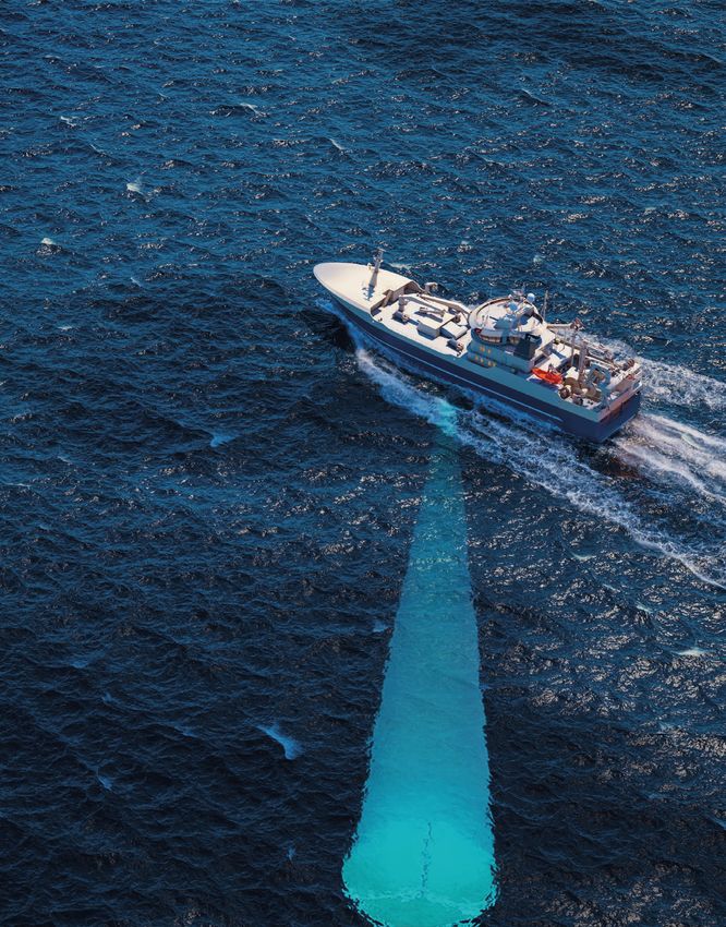
The EK80 calibrates the full beamwidth of
the split beam transducer, and across the
frequency range of the transmission. There will
always be areas where the calibration sphere
has "nulls", frequencies where the sphere has
very low target strenght. While it is these nulls
that allow you to identify the particular target,
these areas are not usable for calibration, and
the EK80 SW lets you adjust the frequency
ranges that are to be used for the particular
calibration. The new and improved EK80 SW
is designed to be intuitive and easy to use,
and this does of course also apply to the
important calibration procedure.
After you have collected data across the
beamwidth it is time to view the data and
apply the calibration. Note the three rings
in the target detection window, where the
centered ring represents the beamwidth at
the center frequency of the transmission. The
outer and inner rings represent the opening
angle at the start and stop frequency. Only
target detections that have been seen across
the frequency band is accepted for the
calibration. If the results appear to be within
the expected variance you save the data,
click the "Finish" button and the system is
calibrated.
26 Single Beam Systems | CalibrationEK TRANSCEIVERS SPECIFICATIONS
WBT WBT Mini WBT Tube WBAT
Frequency Range 10-500 kHz 30-500 kHz 30-500 kHz 30-500 kHz
Pulse Duration 64-16384 µs 64-2048 µs 64-2048 µs 128- 2 µs
CW, FM (up and down sweep),
Pulse Forms CW, FM (upsweep) CW, FM (upsweep) CW, FM (upsweep)
Custom (future option)
Transmit Power 2000 W @55 Ω 1000 W @55 Ω 1000 W @55 Ω 1000 W @55 Ω
Number of Channels 4 4 ( 8 with MUX) 8 (16 with MUX) 4 ( 8 with MUX)
Transducer options Single, Split Single, Split Single, Split Single, Split
Internal memory N/A 512 GB (Aut. Ver.) N/A 512 GB (Aut. Ver.)
Depth / Width / Height 213 / 438 / 84 mm 145 / 223 / 123 mm 701 / 144 / 144 mm 166 / 166 / 1000 mm
Weight air/water 4.9 kg 5.4 / N/A kg 14.1 / 3.6 kg 25/12
Voltage requirement 12-15 VDC 12-16 VDC 12-16 VDC or 20-50 VDC 14 V (internal battery)
Power consumption 38/120/333 kHz 20 / 10 / 5 W 6/3/3W 6 / 3 / 3 W* 6/3/3W
Passive/Standby 4W 2 /FOOTPRINT ON DIFFERENT TRANSDUCER BEAMWIDTHS
Meters 10 20 30 40 50 60 70 80 90 100 110 120 130 140 150
A Feet 33 66 98 131 164 197 230 262 295 328 361 394 426 459 492
Fathoms 5 11 16 22 27 33 38 44 49 55 60 66 71 77 82
A Meters 1 2 4 5 6 7 9 10 11 12 13 15 16 17 18
7o
Feet 4 8 12 16 20 24 28 32 36 40 44 48 52 56 60
Meters 2 4 5 7 9 11 12 14 16 18 19 21 23 25 26
10o
Feet 6 11 17 23 29 34 40 46 52 57 63 69 75 80 86
B
Meters 2 5 7 9 11 14 16 18 21 23 25 27 30 32 34
13o
B Feet 7 15 22 30 37 45 52 60 67 75 82 90 97 105 112
Meters 5 11 16 21 27 32 38 43 48 54 59 64 70 75 80
30o
Feet 18 35 53 70 88 105 123 141 158 176 193 211 228 246 264
RANGE RESOLUTION ON VARIOUS TRANSDUCERS
Range resolution in CW mode is given as half the pulse length. As an example, an EK80 transmission could use 100 kHz
Range resolution in chirp mode however, is given by the bandwidth bandwidth. Assuming a sound speed (c) of 1500 m/s, this will give
(BW), not the pulse duration: a range resolution of about 8 mm, far better than in CW. Range
Range resolution=c/2xBW resolution from the composite transducers is in brackets in the table
below for comparative purposes.
64µS 128µS 256µS 512µS 1024µS 2048µS 4096µS 8192µS
18 kHz 40 cm 75 cm 150 cm 300 cm 600 cm
27 kHz 40 cm 75 cm 150 cm 300 cm 600 cm
38 kHz 20 cm 40 cm 75 cm 150 cm 300 cm
50 kHz 10 cm 20 cm 40 cm 75 cm 150 cm
70 kHz 10 cm (2 cm) 20 cm (2 cm) 40 cm (2 cm) 75 cm (2 cm) 150 cm (2 cm)
120 kHz 10 cm (1 cm) 20 cm (1 cm) 40 cm (1 cm) 75 cm (1 cm)
200 kHz 5 cm (0,8 cm) 10 cm (0,8 cm) 20 cm (0,8 cm) 40 cm (0,8 cm) 75 cm (0,8 cm)
333 kHz 5 cm (0,5 cm) 10 cm (0,5 cm) 20 cm (0,5 cm) 40 cm (0,5 cm) 75 cm (0,5 cm)
The left vessel uses a long pulse duration (C). As you
can see, this causes the echoes from the two fishes (A)
and (B) to merge.
The right vessel uses a shorter pulse duration (D), and
the two fishes will then appear as two separate echoes
on the echogram.
Thus, short pulses will provide the best resolution and
1
1 separation of individual fishes, but the echo sounder is
more sensitive to noise.
2
2
Two targets need to be min. 1/2 pulse length apart, in
order to be seen as two targets. This can be measured
A A in cm. (table above).
B B
This is however not the case with chirp where resolution
C is given by the utilized bandwidth, with range resolution
D
shown in brackets.
( CD010217- 005)
28 Single Beam Systems | SpecificationsDETECTION DEPTHS
FREQUENCY 12 kHz 18 kHz 38 kHz 70 kHz 120 kHz 200 kHz 333 kHz
TRANSDUCER 12-16/60 ES18-11 ES38B ES38-10 ES70-11 ES70-7C ES120-7C ES200-7C ES333-7C
Meters Feet Fathoms
138 m
100 320 55
310 m
360 m
400 m
200 640 109
262 m
570 m
300 960 164
750 m
400 1280 219
910 m
550 m
1000 m
500 1600 273
1200 m
750 m
600 1920 328
970 m
700 2240 383
800 2560 437
SINGLE BEAM SYSTEMS
900 2880 492
1270 m
1000 3200 547
1100 3520 601
1200 3840 656
2450 m
1300 4160 711
1400 4480 765
2730 m
1500 4800 820
2000 6400 1093
2500 8000 1367
3000 9600 1640
3500 11200 1914
7300 m
4000 12800 2187
4500 14400 2460
5000 16000 2734
12000 m
5500 17600 3007
6000 19200 3280
6500 20800 3554
7000 22400 3827
7500 24000 4101
8000 25600 4374
8500 27200 4647
9000 28800 4921
9500 30400 5194
10000 32000 5467
10500 33600 5741
11000 35200 6014
11500 36800 6288
12000 38400 6561
Note: For TS = -32dB in salt water 35ppt and 10° C at 38 kHz this relates to a cod of length 60cm. Bottom Sb = -30dB/m2
Specifications | Single Beam Systems 29"ADCP measurements add a new dimension to the ecosystem overview provided bv the EK80 system." LARS NONBOE ANDERSEN Product Manager Underwater Science
EK80 ADCP
EK80 ADCP
2 in 1, when less is more
Currents play an important role in an aquatic ecosystem, carrying nutrients and biology
or transporting heat.

Scattering from particles in the water will produce doppler effects when moving, which
can be measured and turned into a profile of vertical and horizontal velocity over time.

With the introduction of the very first combined split beam echo sounder and ADCP
(Acoustic Doppler Current Profiler) the EK80 system manifests its position as the most
complete instrument for ecosystem assessments.
EK80 ADCP
CURRENTS AND THE MARINE ECOSYSTEM

An acoustic doppler current profiler measures the speed and direction of the
currents throughout the water column. This offers a valuable tool for understanding
how organisms, nutrients and other biological and chemical constituents are
transported throughout the ocean.

In addition to use travel time of the sound to estimate distance,
the ADCP uses the doppler effect to estimate the water velocity.
The frequency shift of the echo is proportional to the velocity
along the acoustic path, and with multiple measurements
you can get a 3D profile of the water column.

TECHNOLOGY
The acoustic doppler current profiler (ADCP) and narrow split-beam
functionality offered by the Simrad EK80 is based on the EC150-3C
transducer. The EC150-3C is a phased array transducer resulting
from decades of experience building acoustic instruments. The
transducer combines composite technology with built-in electronics,
allowing for a compact and easy installation. By combining wideband
elements, the transducer allows for both narrowband (CW) or
wideband (FM) signals to be used based on user requirements. The
phased array also allows for a very narrow, split beam, echo sounder
beam to be created by the same transducer.

     TECHNICAL SPECIFICATIONS
     OVERALL PERFORMANCE                                                 PROCESSOR UNIT
       Nominal frequency: 150 kHz                                          Computer: EK80 Processor Unit
       Frequency range: 130 to 170 kHz                                     Operating system: Windows® 10
       Dynamic range: 135 dB                                               Software: EK80

     ADCP PERFORMANCE                                                    INTERFACES
       Number of beams: 4                                                   Internal sensor: Temperature
       Beam vertical tilt: 30 degrees                                       External sensors: Position, Attitude and Heading
       Beam width: 3 degrees @ 150 kHz
       Pulse type: CW or FM                                              EC150-3C CONNECTIONS
       Cell size: 2 to 16 m                                                A dedicated 40 m open ended cable
       Max output sample interval: 40 μs                                   is provided with the transducer.
       Max number of depth cells: Unlimited
       Max range: > 400 m @ CW, 8 m cell size                            EC150-3C POWER REQUIREMENTS
     Maximum range depends on the acoustic scattering conditions.          Voltage requirement: 115 to 230 VAC, 50-60 Hz (nominal)
                                                                           Power consumption: 70 W
     ECHO SOUNDER PERFORMANCE                                              Inrush current: 30 A with cold start @ 230VAC/25°C
       Number of beams: 1 split beam                                       Input current:
A NEW FUNCTIONALITY IN A PROVEN SYSTEM
Data acquisition and storage of the Simrad ADCP is done by the EK80 SW, which provides several advantages for the
user. First of all, EK80 is already installed on most research vessels, which means you can reduce the complexity of the
installation. Also, the space requirement is reduced, since you only need one operator station. Then, lower installation and
maintenance lead to a cost effective improvement. Additionally, having the same SW taking care of both measurements
EK80 ADCP
eases the task of synchronizing, which is a challenge even with an external synchronizing unit. Finally, the EK80 is a user
friendly, well proven software that leaves the user in full control of all parameters, a basic requirements for a scientific user.
The EK80 stores the ADCP data in NetCDF format, and auxiliary data such as motion and position data are recorded in the
data files.
THE ADDITIONAL ECHOSOUNDER
In addition to being an ADCP, the EC150-3C allows for the combined elements to be used to produce a very narrow,
wideband echosounder beam. The built-in echo sounder adds a new dimension on its own, providing a high resolution
echosounder at no extra effort. However, also as part of a multifrequency EK80 setup the 3 degree opening angle
supplements the other transducers by improving the systems ability to pick out individual targets within aggregations.
EK80 ADCP 33"The scientific multibeam systems represent outstanding innovation in transducer technology, mechanical design, beam forming, and signal processing solutions." LARS NONBOE ANDERSEN Product Manager Underwater Science
MULTIBEAM
SYSTEMS
Take your survey to the next level

                                                                                         MULTIBEAM SYSTEMS
Multibeam systems have been used for decades to detect, inspect and map bottom
and manmade structures in the water, but the application within fishery and ecosystem
surveys is relatively new.

With the introduction of the first quantitative Multibeam systems in the world, SIMRAD
has added new dimensions to biological surveys, providing 3D and even 4D data from
the marine ecosystem.

The combination of high resolution quantitative data, extremely low side lobes and no
cross talks between the beams has already proven to strengthen our understanding of
marine life.
SIMRAD ME70 SCIENTIFIC
MULTIBEAM ECHO SOUNDER
A scientific multibeam echo sounder can be seen as many
EK sounders spread out in a fan of beams. Where the EK
provides multifrequency analysis, the ME70 adds to the
picture with morphology and volume information, improved
horizontal resolution and in general, it samples more cubic of
water along the survey line.
What makes the ME70 truly unique is that it combines the
quantitative element from the split beam sounders with
the resolution and the extended sampling volume from the
multibeam world. As each beam is configured as split beam,
standard split beam calibration techniques can be applied to
the entire swath. When you have the system calibrated, you
can both visualize and quantify your targets.
The combination of multiple, narrow beams with low side
lobes strengthen your capability to measure targets in the
acoustic dead zone close to the sea bottom. In addition to
the obvious fish and marine mammals, other targets such as
methane gas seeps and seafloor vegetation can be measured
with calibrated backscatter values. The increased sampling
volume from a swath system also addresses the acoustic
dead zone in the upper layers of the water column as the fan
of beams cover approximately 10 times the width compared
to the 7° single beam.
MORPHOLOGY AND BEHAVIOUR
Much information can be derived from understanding the swath, but rather show the real boundaries of the school.
morphology of schooling fish. Perhaps most obvious; The same applies for marine habitats where the bottom
your estimation of the size on that particular school will echo is the dominant scatterer. Thanks to the advanced
improve. However, school morphology can also improve beamforming and side lobe suppression techniques of the
your species identification as various fish show different ME70, the bottom echo would not shadow other smaller
characteristics in the way they interact both within the targets.
school and together with the surrounding environment.
To investigate a complete marine ecosystem is a
Predator/prey, or who is feeding on who, is also important challenge. Using single beam acoustics can be compared
information when you assess the ecosystem. The ME70 with looking through a peephole, whereas the ME70
offers extremely low sidelobes and high dynamic range, widens your vision and is more like looking through a
something that is vital when it comes to measuring a fish window. The 3D information given by the ME70 adds
close to bottom, or plankton near a school of fish. The two spatial resolution and improves your stock assessment.
way side lobe suppression offered by the ME70 means
that a school of fish will not be smeared out across the
36 Multibeam Systems | ME SystemsThis picture shows a school of sand eel close to the bottom.
The sand eel typically burrows in the sand to escape predators
during daytime, while at night time it feeds on plankton and
other small creatures. You can actually see how the school
maintains contact with the sand even when the main population
feeds in the water column. The only reason we can record such
details near the bottom is the ultra-low sidelobes coupled with
the advantages of frequency rotation between the beams.
This data were recorded with the ME70 and has since then
been processed and visualized by a third party software. As
with all SIMRAD RAW data, the ME70 data format is open and
well documented.
MULTIBEAM SYSTEMS
ME Systems | Multibeam Systems 37ME70 BATHYMETRIC OPTION
The seafloor is an important component of the marine and x,y,z data generation developed by the hydrographic
ecosystem. Perhaps you are looking at vegetation that department of Kongsberg Maritime.
grows on the bottom or fish that thrive near the bottom. Or
perhaps the bottom structures themselves are of interest
to the assessment such as presence of coral reefs in the
area.
The advantages of using a multibeam system when
studying the seafloor are obvious, multiple detection points
from an array of narrow beams are better than a single,
wide beam. With the introduction of the ME70 scientists
can now survey the seafloor while doing quantitative
studies for biology at the same time. The ME70 is
calibrated with a sphere with known target strength, and
backscatter data can therefore be compared across
various study areas.
If you want one multibeam system to do both quantitative
water column work and bottom mapping, the ME70 is
your only logical choice. The system can provide IHO Kongsberg’s own Seafloor Identification System (SIS)
S44 Order 1 data, and fulfils the demanding LINZ order is also included in the delivery, adding an extensive set
1 survey specification to be met in full. The bathymetric of graphical displays for data quality control, as well
system includes a special bathymetric processor unit for as system calibration, data cleaning, gridding, and
bottom detection, ray tracing, extra motion correction, visualization.
38 Multibeam Systems | ME SystemsEXTERNAL SENSORS AND GEOMETRICAL
MEASUREMENTS OF VESSEL
The multibeam echo sounder needs the following information from Which sensor to use depends on the survey requirements. Kongsberg
external sensors to function correctly: Maritime's Seapath 300 family provides a combined motion sensor
and GPS that produces position, heading, and vessel motions from
Position one integrated device. Upon request, we can suggest external sensors
Heading that fulfill the particular survey needs.
Vessel motion: pitch, roll and heave
Sound velocity at the transducer depth It is also recommended to do a very accurate measurement of the
Sound velocity profile through water column vessel including transducer position inside the hull. The need for
Potentially others, such as very accurate time stamp accuracy varies with user need, but we always recommend to use land
surveying techniques that can be performed by third party companies.
Here we have a screenshot from
the ME70 acquisition software. On
the centre of the image we see the
combined swath of beams athwartship.
The software is flexible: it not only
MULTIBEAM SYSTEMS
shows the individual beams of your
choice, but you can also see split beam
information, such as size, from each
beam.
In this screenshot we can see another
school, but this one displaying
very different schooling behaviour.
Understanding the school's
morphology has never been so easy.
ME Systems | Multibeam Systems 39SIMRAD MS70 SCIENTIFIC
MULTIBEAM SONAR
The MS70 provides an acoustic matrix of stabilized and
calibrated beams for biomass estimation and study of
school behaviour. Advanced beam forming is used to form
500 beams, spread out 60° horizontally by 45° vertically.
As a result of this optimized horizontal transmission of
narrow beams, the MS70 allows the user to detect and
characterize schools of fish even very close to the sea
surface.
Where the ME70 adds a third dimension to your survey,
the MS70 adds a 4th dimension. When you add up
distance, vertical and horizontal swath of beams in
addition to time from multiple transmissions, in reality
what you have is an acoustic camera. As a school of fish
changes shape and density constantly, the MS70 is the
best possible tool to understand these dynamics with
remote sensing.
As with all Simrad scientific systems, a calibration utility is During the calibration process, the MS70 automatically generates
implemented as a special built-in function in the SW. The sonar is 500 split beams in order to measure the target position within
calibrated using a reference sphere that needs to be located on the each beam. Individual gain parameters for each beam are adjusted
side of the ship. to provide calibrated target strength and volume backscattering
strength.
CALIBRATION SPHERE
40 Multibeam Systems | MS SystemsTHE CHALLENGE OF STUDYING SCHOOLING
FISH CLOSE TO SURFACE
Low sidelobes are important for at least two
reasons. The obvious one is to avoid that a
strong target in the side lobes are mistaken
for weak targets in the main lobe. Secondly,
you do not wish to see strong bottom echoes
from the sidelobes.
Surface is a very strong reflector, and the
two-way vertical side lobe suppression of
the MS70 secures that reflections from the
surface does not contribute to the school
estimate. Also, the frequency band of the
system is distributed out across the matrix,
with minimal leakage between the many
beams.
The frequency
bandwith is
distributed
between the 500
MULTIBEAM SYSTEMS
beams.
This screenshot shows a school of herring. Even though the
MS70 detects and records data from all 500 beams, only
two sectors can be shown in a traditional 2D view. One is a
horizontal slice, while the other is a vertical slice through the
matrix. In addition to that, you can have a zoon view and an
echogram from the single beam shared by the two sectors.
MS Systems | Multibeam Systems 41MULTIBEAM SPECIFICATIONS
ME70 ME70 BATHY MODE MS70
Beam organization Fan Matrix
Operating sector 2 to 140° 120° 60° x 45° (H x V)
Minimum beamwidths 2° x 2° 3° x 2° (along x athw.) 4° x 3° (H x V)
Operating frequency 70-120 kHz 75-112 kHz
Max no. beams 45 split beams 81 split beams 500
Beam stabilization Roll & pitch Roll
SIDELOBE SUPPRESSSION
Sidelobe levels -35 to -70 dB -35 x -25 (along x atw.) H: -35 dB, V: -25 dB
Pulse duration 64 to 5120 µs 64 to 5120 µs 2-10 ms
DYNAMIC RANGE
Max. source level 225 dB 216 dB 206 dB
TRANSCEIVER UNIT
TX/RX channels 800 individual channels
Modulation CW or chirp
Communication 2 x 1 Gb Ethernet lines
Physical size 1200 x 600 x 900 (H x B x D)
TRANSDUCER UNIT
Number of elements 800 individual elements
Material Ceramic polymer composite
Physical size Circular, 670 mm, H; 400 mm
SIMRAD SCIENTIFIC MULTIBEAM SYSTEMS
B
A E
SIMRAD SIMRAD
MENU MENU
C
PW R PWR
SIMRAD ME70 SIMRAD ME70
F
SYSTEM DIAGRAM
Interface capabilities, uninterrupted power supplies A. Processor Unit for operation and beamforming with colour display
and power cables are not shown. B. Transceiver Unit
C. Power Supply Units
D. Transducer (mounted sideways with MS, downward with ME)
E. Hydrographic workstation with colour display (ME70 Bathy only)
F. Bathymetric option processing unit (ME70 Bathy only)
D
42 Multibeam Systems | SpecificationsINCREASED EFFECTIVE SAMPLING VOLUME
A scientific multibeam echo sounder can be seen as many EK sounders spread out in a fan of
beams. With more narrow beams spread out in a wide swath, you increase both your resolution
and sample volume at the same time. The system can be configured to fit your preferences.
Below, we can see a 60° swath and its corresponding sampling volume.
1000 meters
1000 meters
800 meters
600 meters
400 meters
200 meters
200 meters
400 meters
600 meters
800 meters
0 meters
Range
0
50
100
150 Depth
200
250
300
350
400
450
500
550
600
650
700
MULTIBEAM SYSTEMS
750
800
850
900
950
1000
1050
1100
1150
1200
ME70 swath
ME70 centre beam
Specifications | Multibeam Systems 43"Our sonars are based on:
- Efficent transducers with
- Clean beams and
- Complex signals with
advanced signal processing
The Simrad sonars are designed
and produced in house, which
means that we have full control of
the product."
MARTIN TOLLEFSEN
Product Manager
SonarsSONARS
Already a success!
The first Simrad sonars introduced on research vessels were delivered for the Norwegian
vessels “Johan Hjort” and “G.O. Sars” back in the late 1950’s. These were combined
sonars and echo sounders, considered very advanced at that time. Since their
introduction, the sonars have evolved to become highly efficient tools to detect any
object in the water column with a number of revolutionary features.
Today, the sonar family has grown to include 4 different omni directional sonars: low
SONARS
frequency (SU90, SX90, ST90) and high frequency (CS90).
In addition to finding and tracking objects in the water column, the Simrad sonars are
now being converted into scientific tools, with the introduction of RAW data output and
new calibration techniques.
The sonar is also the Captain's eyes under water, valuable during fishing operations or
when navigating in confined waters.ST90
#RANGEDEFINITION
SIMRAD is continuously developing the sonar range by utilizing the
latest in technology combined with over 70 years of experience. The
latest achievement is the new low frequency sonar, ST90. Our current
low frequency sonars (SX90 and SU90) have been in the 20-30kHz
range. With the ST90 we have lowered this range to 14-22kHz. In
order to achieve this, a completely new transducer has been designed.
Each element is larger than the previous, but the amount of elements
are the same as the SU90, giving the same narrow beam and ultimately
a longer range.
The ST90 is made to search at very long range in all conditions.
Whether it is heavy weather, hard bottom, open waters, weak targets
it all will be handled by the ST90 due to the fully stabilized and very
narrow beams combined with state of the art signal processing.
The ST90 will also feature the new and powerful Winson sonar
operating SW with all the new benefits like multiple monitor, “all beams
in one ping” and so forth. Please see the new sonar SW section where
this is described in more detail.
NEW WINSON SONAR OPERATING SOFTWARE
NEW WINSON SONAR OPERATING SOFTWARE “ALL IN ONE PING”
The current operating software in Simrad sonars has been Modern sonars today use multiple pings to generate the various
a tremendous success with its intuitive and easy to use views. For example, one for the omni 360° view and maybe
interface. Now it is time to take this success to another level by two different vertical view are three pings, now all three will be
introducing the new operating software already operational in our transmitted and received in one ping. This dramatically improves
echosounders, catch monitoring systems and SN90 sonar. This will the update rate on the screens giving a more real time information.
complete our mission of having one unified interface between the
user and the product regardless of what product you are operating. RECORDING
Great new features are also a part of this upgrade. The new operational software is now enabled to record real time
situations. Before, only screen captures were recorded. Now the
OPTIMIZED FOR MULTIPLE DISPLAYS real echoes are recorded making it possible to replay sequences
The new “docking” function enables the user to take any window like in real life. During playback vital information can be viewed for
and place it on a separate screen or display. If you move the training and/or troubleshooting purposes.
vertical view to another display, it will automatically scale the
window for best viewing of long range in shallow water for example. TRACKER FUNCTION
The tracker function has been further developed and can now
utilize information from both the horizontal and vertical ping.
46 Sonars ST90 Low frequency sonarYou can also read