Advances in Operational Weather Radar Technology
←
→
Page content transcription
If your browser does not render page correctly, please read the page content below
• weber
                                     Advances in Operational Weather Radar Technology

Advances in Operational
Weather Radar Technology
Mark E. Weber
n The U.S. aviation system makes extensive use of national operational Doppler
weather radar networks. These are critical for the detection and forecasting of
thunderstorms and other hazardous weather phenomena, and they provide dense,
continuously updated measurements of precipitation and wind fields as inputs
to high-resolution numerical weather prediction models. This article describes
recent Lincoln Laboratory activities that significantly enhance the operational
effectiveness of the nation’s Doppler weather radar networks. An open radar
controller and digital signal processor has been developed for the Terminal
Doppler Weather Radar (TDWR), which provides safety-critical low-altitude
wind-shear warnings at large airports. This processor utilizes a small computer
cluster architecture and standards-based software to realize high throughput
and expansion capability. Innovative signal processing algorithms—enabled by
the new processor—significantly improve the quality of the precipitation and
wind measurements provided by TDWR. In a parallel effort, the Laboratory is
working with engineers in the National Weather Service to augment the national
NEXRAD Doppler weather radar network’s algorithm suite. Laboratory staff
develop and test enhancements directed at the aviation weather problem. Then
they provide plug-and-play software to the NEXRAD second-level engineering
support organization. This effort has substantially improved the operational value
of NEXRAD data for the aviation system. Finally, we discuss nascent efforts to
define a future multifunction radar network using an active-array architecture,
which could realize the capabilities of today’s multiple weather and air traffic
control radar networks.

L
        incoln laboratory has played a significant              minal Doppler Weather Radar (TDWR) that detects
        role in the development and application of              and warns against this hazard at major airports. The
        U.S. operational weather radar networks. Early          Laboratory’s role in developing automated wind-shear
efforts addressed the then-under-development Next               detection algorithms for TDWR, demonstrating these
Generation Weather Radar (NEXRAD) and included                  operationally on a transportable testbed, and transfer-
analyses of ground-clutter suppression requirements             ring key technology elements to industry was critical
[1] and experimental evaluation of Doppler spectrum-            to the successful deployment of this system [3].
based turbulence estimators [2]. In response to a series            A complementary wind-shear detection system uti-
of commercial aviation accidents caused by low-alti-            lizing deployed Airport Surveillance Radars (ASR-9)
tude wind shear, the Federal Aviation Administration            was developed by the Laboratory [4] and is now op-
(FAA) initiated a fast-track program to develop a Ter-          erational at thirty-four airports that did not receive the

VOLUME 16, NUMBER 1, 2006 LINCOLN LABORATORY JOURNAL 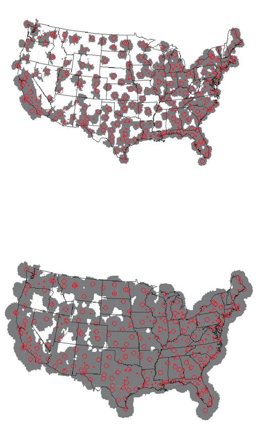
• weber
                                              Advances in Operational Weather Radar Technology

TDWR. Finally, Laboratory researchers have played
                                                                         U.S. Operational Weather Radar Networks
a significant role in validating and refining industry-
developed weather reflectivity processing channels                       The Weather Service Radar 88-D (WSR-88D, or
for U.S. terminal air traffic control radars ASR-9 and                   NEXRAD) was developed by Unisys Corporation in
ASR-11 [5].                                                              the 1980s, using technical specifications developed by
    Other Laboratory programs have exploited these                       scientists at the National Severe Storms Laboratory
Doppler weather radars as key inputs to integrated                       and other organizations. The radar operates at 10 cm
weather processing systems focused on reducing com-                      wavelength, utilizes a 1° transmit and receive beam,
mercial aviation delay caused by adverse weather. The                    and transmits uncoded 750 kW pulses with selectable
Integrated Terminal Weather System (ITWS) [6] and                        durations of 1.6 or 4.7 msec. NEXRAD is fully coher-
Corridor Integrated Weather System (CIWS) [7] uti-                       ent to support ground-clutter suppression and weather
lize NEXRAD, TDWR, and ASR-9 measurements to                             Doppler spectrum moment estimation. One hundred
detect and forecast thunderstorm impacts on runways,                     forty-three NEXRADs are deployed within the Con-
terminal gateposts, and high-altitude jet routes.                        terminous United States (CONUS).
    Key aspects of the processing algorithms in these                       NEXRAD data and derived products are dissemi-
systems derive from insights gained during the Lab-                      nated to National Weather Service (NWS) personnel
oratory’s development of their input weather radar                       at Weather Forecast Offices and a variety of private
systems. Data quality control—for example, robust                        and media weather service providers. The Laboratory’s
ground-clutter suppression and suppression of inter-                     engagement with this radar has been primarily in rela-
ference from distant range-ambiguous thunderstorm                        tion to its important role in providing thunderstorm
returns—is critical if Doppler weather radar data are                    location, intensity, characterization, and movement
to be used effectively in automated warning and fore-                    information to FAA and airline personnel through sys-
casting algorithms. Likewise, detailed understanding                     tems such as the ITWS, CIWS, and Weather and Ra-
of the differing and often complementary characteris-                    dar Processor (WARP) [8]. The NEXRAD network’s
tics of storm measurements obtained from these mul-                      key attributes include national-scale coverage, opera-
tiple radar systems has been important in developing                     tion at a non-attenuating wavelength, and connectivi-
effective decision support information for FAA and                       ty to essentially all operational weather personnel deal-
airline operational personnel.                                           ing with public and aviation weather services.
    This article describes recent Lincoln Laboratory ac-                    Terminal Doppler Weather Radar was manufac-
tivities that enhance the nation’s current operational                   tured by Raytheon Corporation in the late 1980s us-
Doppler weather radar networks, and nascent efforts                      ing technical specifications developed by the FAA and
to define a next-generation multifunction replace-                       Lincoln Laboratory. Because spectrum availability at
ment network. The next section describes current op-                     10 cm wavelength was limited by in-place Airport Sur-
erational weather surveillance radar networks and the                    veillance Radars and NEXRAD, TDWR operates at 5
aviation-sector uses of each system. A subsequent sec-                   cm. TDWR generates a 0.5° pencil beam and trans-
tion discusses a signal processor enhancement for the                    mits uncoded, 1 msec, 250 kW pulses. Its sensitivity
TDWR, which significantly improves both support-                         to volume-filling precipitation particles is essentially
ability and operational capabilities. We then describe                   identical to NEXRAD. TDWR is deployed operation-
our use of NEXRAD open-processing systems to                             ally at forty-five large U.S. airports.
implement algorithms that substantially improve the                         Currently, TDWR is used primarily for wind-shear
value of this radar to FAA operational systems. Finally,                 detection services at the airports where it is deployed.
we describe a concept definition study for a multi-                      It is also an input to the ITWS, which uses TDWR
function phased-array radar that could replace cur-                      data for wind-shear prediction and a high-resolution
rent weather and aircraft surveillance radar networks,                   gridded wind diagnosis [9] that enhances capacity at
potentially realizing both performance enhancements                      major airports during high wind conditions [10]. Be-
and cost reductions.                                                     cause of TDWRs siting near major metropolitan areas,

10     LINCOLN LABORATORY JOURNAL   VOLUME 16, NUMBER 1, 2006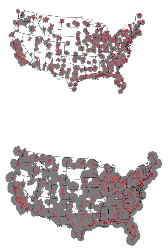
• weber
                                     Advances in Operational Weather Radar Technology

its twofold angular resolution improvement relative to          NWS is actively pursuing ingest of ARSR-4 weather
NEXRAD, and its aggressive ground-clutter suppres-              data as a gap filler for the NEXRAD network.
sion algorithms, there is increasing interest in use of
its data for applications beyond the immediate airport          Terminal Doppler Weather Radar
vicinity. NWS has established a program to access data          Processor Enhancement
from all TDWRs and to process these data in the ap-             TDWR provides a unique capability for high-qual-
propriate Weather Forecast Offices as an adjunct to             ity precipitation and wind measurements, particularly
NEXRAD. Researchers developing advanced algo-                   in the planetary boundary layer where most signifi-
rithms for forecasting future thunderstorm impacts              cant weather conditions have their roots. The radar
on the airspace system view TDWR data as impor-                 features very high angular resolution, high sensitivity
tant, because of the ability of its high-resolution beam        to weak clear-air meteorological signals, and a highly
to capture boundary-layer wind structures that lead             stable Klystron transmitter that supports robust Dop-
to new storm initiation. Future configurations of the           pler clutter filtering. Operational experience over the
CIWS will include TDWR data ingest and processing               last decade with fielded TDWRs has, however, ex-
for this purpose.                                               posed data quality issues that can reduce the reliability
    In addition to these meteorological radars, the U.S.        of automated applications that utilize its data. Most
Government operates two distinct surveillance radar             significant are the impacts of range-ambiguous thun-
networks for Air Traffic Control (ATC) services. Air-           derstorm echoes, which can overlay operationally sig-
port Surveillance Radars (ASR) operate at 10 cm wave-           nificant Doppler wind signatures at close range, and
length and utilize a doubly curved reflector to detect          challenges associated with aliased Doppler velocity. A
aircraft returns in range-azimuth space by using a 1.4°         second major data quality assurance challenge is the
(azimuth) by 5° (elevation) cosecant-squared beam.              extraction of low-altitude Doppler velocity estimates
Modern ASRs—the Westinghouse-manufactured                       in the presence of strong ground clutter, particularly
ASR-9 and the Raytheon-manufactured ASR-11—                     that associated with moving automobile traffic.
provide parallel data processing chains that display to            In 2002, the FAA asked Lincoln Laboratory to
terminal controllers calibrated maps of the intensity of        develop a modern replacement for the TDWR’s Ra-
precipitation as sensed by their vertically integrating         dar Data Acquisition (RDA) subsystem. The RDA is
beams. Thirty-four ASR-9 radars are equipped with               responsible for transmitter and antenna control, sig-
the Lincoln Laboratory–developed Weather Systems                nal reception, and signal processing. Its outputs are
Processor (WSP), which additionally detects low-alti-           range-azimuth-elevation fields of precipitation reflec-
tude wind shear and provides zero-to-twenty-minute              tivity, mean Doppler velocity, and Doppler spectrum
forecasts of thunderstorm future location.                      width (so-called base data). These base data are pro-
    Air Route Surveillance Radars (ARSR) provide na-            cessed by the TDWR’s internal wind-shear detection
tional-scale primary aircraft surveillance. The ARSRs           algorithms as well as the external systems mentioned
currently in operation date back to the ARSR-1 and              in the preceding section. A team led by Gabriel Elkin
ARSR-2 systems deployed in the 1960s. The Depart-               and Nathan Parker in the Weather Sensing group at
ments of Defense (DoD) and the Department of                    the Laboratory has developed a contemporary, open
Homeland Security (DHS) have recently assumed re-               RDA subsystem that will support substantially more
sponsibility for operation, sustainment, and upgrades           effective algorithms for the generation of high-quality
to the ARSR network, although technical support                 base data. Of particular note is the capability to adapt
is still subcontracted to the FAA. The most modern              transmitted waveforms and processing algorithms on
ARSR—the Westinghouse-developed ARSR-4—em-                      a radial-by-radial basis to the characteristics of the
ploys a phased primary feed that supports the forma-            weather and clutter environment.
tion of an elevation receive stack of 2° pencil beams.             Figure 1 depicts the Laboratory-developed RDA
A weather processing channel derives quantitative pre-          replacement system. A Quad Intel Xeon processor
cipitation reflectivity estimates from these beams. The         performs both signal processing and system control

                                                                         VOLUME 16, NUMBER 1, 2006   LINCOLN LABORATORY JOURNAL   11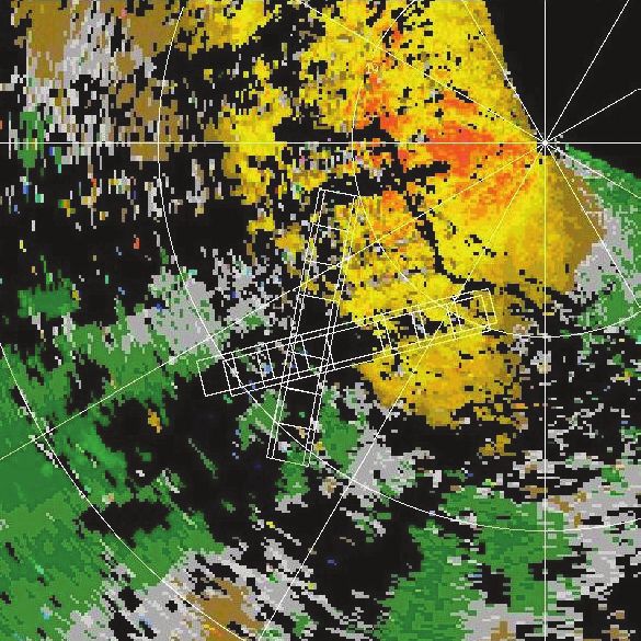
• weber
                                                 Advances in Operational Weather Radar Technology

                                                                               TDWR

                                            Transmitter                 Pedestal           Down converter
                  RDA

                                           Up converter                                   14-bit IF digitizer

                                             Digital
                        Sigmet                                           Digital              Receiver
                                            waveform
                        RVP8                                            I/O card               card
                                            generator

                      PCI bus

                                                                            CPU         CPU        CPU          CPU
                      Control and compute server

                                                                                   Gigabit Ethernet

                                                           I & Q data

                                   Extra           Extra                      Status and
                                   DSP             DSP                         control             RMS
                                   slave           slave                                                          Downstream
                                                                                                   and
                                                                                                                    users
                                                                              Base data            RPG
                                   Future expansion                           products

      FIGURE 1. Hardware and software architecture of Terminal Doppler Weather Radar (TDWR) radar data acquisi-
      tion (RDA) subsystem replacement. A commercial off-the-shelf computer with four Intel Xeon processors per-
      forms both signal processing and system control functions. The SIGMET RVP8—three PCI cards utilizing field
      programmable gate array chips—provides digital waveform generation, high-dynamic range digital intermediate
      frequency signal reception, and system timing. The RDA can be scaled to handle larger processing loads by add-
      ing additional processor nodes, interconnected using gigabit Ethernet.

functions. The processor operates under the Linux                                  sor nodes, interconnected using gigabit Ethernet.
operating system. The commercially built SIGMET                                    This capability will support ongoing enhancements
RVP8—three PCI cards, utilizing field programma-                                   to the TDWR’s signal processing algorithms such as
ble gate array chips—provides digital waveform gen-                                those discussed later in this section. A software stan-
eration, high-dynamic-range digital intermediate fre-                              dard called Message Passing Interface can distribute
quency signal reception, and system timing. As shown                               in-phase and quadrature (I&Q) signals to a cluster of
in the figure, the RDA can be scaled to handle larger                              digital signal processor slaves. These process the data
processing loads by adding additional Linux proces-                                in parallel and recombine their outputs prior to trans-

12    LINCOLN LABORATORY JOURNAL       VOLUME 16, NUMBER 1, 2006
• weber
                                        Advances in Operational Weather Radar Technology

                                                              TDWR unambiguous range limit

                                                                                                               Thunderstorm

                        Gust front leading edge

                TDWR

                                   Apparent
                                (range-aliased)
                             thunderstorm position                                                          True
                                                                                                        thunderstorm
                                                                                                           position

                 Airport

FIGURE 2. Illustration of TDWR range-overlay challenge. In this notional scenario, the outflow boundary, or gust front lead-
ing edge, from a thunderstorm complex has propagated well ahead of its parent thunderstorm. Because a portion of the parent
storm is beyond the radar’s unambiguous range limit, its echo from the preceding transmitted pulse is coincident with first-trip
echoes from the gust front. The resulting range overlay interference may prevent detection of the gust front.

mitting the base data to downstream clients. All the               volume) typically exceeds by 35 dB the reflectivity of
software employs standards-based interfaces and is                 the precipitation-free air through which the leading
thus transportable essentially unchanged to enhanced               gust front propagates. Since echo strength for beam-
commercial off-the-shelf (COTS) processors as these                filling precipitation decreases only as 1/range2, the dis-
become available.                                                  tant thunderstorm echo is often substantially stronger
                                                                   than the close-in gust front return. Current TDWR
Range-Doppler Ambiguity Mitigation                                 processing utilizes range-unambiguous data from an
Signals from thunderstorms at ranges greater than                  occasional low pulse repetition frequency (PRF) scan
the unambiguous range—cT/2, where c is the speed                   to recognize the occurrence of this situation. However,
of light and T is the pulse repetition interval (PRI)—             because the system does not have waveforms and al-
may overlay lower-power Doppler wind signatures                    gorithms to suppress the interfering range-ambiguous
of operational significance near the TDWR. Figure                  echoes, data from affected range gates must simply be
2 illustrates a frequent scenario in which the outflow             censored.
boundary, or gust front, from a thunderstorm com-                      A related data-quality problem is Doppler veloc-
plex propagates 100 km or more ahead of some of the                ity aliasing in areas of high wind speed. TDWR must
storm cells. As the front passes over a TDWR-protect-              be range-unambiguous over its 50 nmi instrumented
ed airport it produces a sudden, potentially hazardous             range. The highest PRF available to the system is 1931
shift in wind speed and direction, turbulence, and a               sec–1, which results in an unambiguous Doppler interval
sustained change in wind direction that may require                of ± 26 m/sec. Wind speeds in the atmosphere frequent-
air traffic controllers to change the airport’s runway             ly exceed this limit. In order to ensure detection and ac-
usage configuration. In the illustrated scenario, how-             curate strength characterization of strong low-altitude
ever, the gust front is not detected because the overlaid          wind-shear events, the TDWR must de-alias Doppler
signal power from distant thunderstorm cells signifi-              wind estimates. The current approach to de-aliasing
cantly exceeds the echo strength of the gust front. The            utilizes a combination of signal processing, image con-
thunderstorm’s radar reflectivity (cross section per unit          tinuity arguments, and constraints imposed by a con-

                                                                            VOLUME 16, NUMBER 1, 2006       LINCOLN LABORATORY JOURNAL   13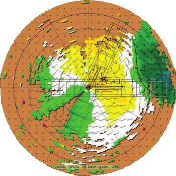
• weber
                                                                  Advances in Operational Weather Radar Technology

tinuously updated wind field model [11]. The method,                                                   determining the true velocity that is consistent with the
however, has proven to be problematic in many scenari-                                                 aliased velocity estimates from the different PRI pulse
os, resulting in adjusted Doppler velocity estimates over                                              batches. The unfolded-velocity cluster method [13], ap-
large areas, which may be off by multiples of the Ny-                                                  plied to all PRI batches that are free of range overlays, is
quist interval. The most frequent manifestation of de-                                                 used to determine the true wind velocity.
aliasing errors is wind-shear false alarms caused by the                                                   A second approach to range-overlay protection is to
artificial velocity discontinuities that result.                                                       apply a pseudo-random variation to the initial phase of
    The enhanced RDA will exploit substantially more                                                   pulses transmitted within a coherent processing inter-
complex waveforms and signal processing approaches                                                     val. As Figure 3 illustrates, returns from any unambigu-
developed by John Cho in the Weather Sensing group                                                     ous range interval—or ‘trip’—can be selectively cohered
to mitigate the impacts of range- and Doppler-ambigu-                                                  by appropriately shifting the pattern of the complex
ous weather returns. Two techniques are utilized: multi-                                               weights applied to the echo time samples. Signals re-
PRI and pseudo-random pulse phase coding. With the                                                     turned from trips other than the one selected are whit-
multi-PRI waveform, the radar coherent processing                                                      ened in Doppler space. The figure illustrates how this
interval is divided into a sequence of pulse batches at                                                selective cohering technique can be used to suppress
different PRIs. A typical multi-PRI coherent process-                                                  range-overlaid weather returns. This approach requires
ing interval would consist of 64 total pulses, subdivided                                              that the PRI within the coherent processing interval be
into eight batches of eight pulses. Within each batch,                                                 constant so that the requisite forward- and inverse-Fou-
the PRI is constant but the PRIs of the different batches                                              rier transforms can be computed. To accomplish Dop-
might range from 600 msec to 936 msec. Range-am-                                                       pler velocity de-aliasing, the PRI is varied on alternate
biguous thunderstorm echoes from the different pulse                                                   radials and the cluster method referenced above is ap-
batches fold onto different sets of range gates in the op-                                             plied.
erationally important ‘first trip,’ that is, the range inter-                                              The multi-PRI and phase code techniques have
val from 0 to cT/2. Reflectivity and Doppler velocity                                                  complementary strengths and weaknesses, as described
estimates are formed by using the auto-covariance, or                                                  by Cho et al. [14]. Multi-PRI signals provide robust
‘pulse-pair’ algorithm [12] applied to those pulse batch-                                              overlay protection as long as the distant weather does
es that are free of range overlays. Thus interference-free                                             not span such a large range interval that none of the dif-
weather parameter estimates can be generated as long as                                                ferent pulse batches are free from overlays. For the range
some of the different PRI pulse batches are ‘clean.’ Ve-                                               of PRIs available in the TDWR system, this restric-
locity de-aliasing is accomplished with this waveform by                                               tion corresponds to a range-extent limit for the distant

                                     Waveform
                                                                                                                            Second trip    First trip    Second trip
                                                                                                              First trip
                                                                                                                                  Noise
         Phase φ 1 φ 2 φ 3 φ 4 φ 5 φ 6 φ 7 φ 8 φ 1 φ 2

                                                                                                                  True spectrum           Cohered for second trip

                        Receiver phase multipliers
                       for recohering selected trip                                                            First trip

     First trip   φ∗1 φ∗2 φ∗3 φ∗4 φ∗5 φ∗6 φ∗7 φ∗8 φ∗1 φ∗2                                                                            Recohere            Filter
                                                                                                                                         for            second
Second trip       φ∗   8   φ∗   1   φ∗   2   φ∗3   φ∗   4   φ∗5    φ∗   6   φ∗   7   φ∗8   φ∗1                                        first trip          trip

FIGURE 3. Illustration of pulse phase code processing. The transmitted signal waveform and receive sample complex weights
required to recohere first-trip or second-trip returns are illustrated on the left. The overlay suppression algorithm is sketched on
the right, as applied to a range gate where a strong, second-trip return overlays a first-trip echo.

14       LINCOLN LABORATORY JOURNAL                VOLUME 16, NUMBER 1, 2006
• weber
Advances in Operational Weather Radar Technology
Multi-PRI
Determine distant transmission/processing
Select
Long-PRI weather distribution
transmission/processing
pulse samples and compute
for each radial
range folding Phase-code
transmission/processing
FIGURE 4. Adaptive waveform selection algorithm that uses data from a range-unambiguous low PRF tilt to select the
processing approach for subsequent high-PRF scans.
weather of approximately 60 km. The phase-code tech- portions of this front. It is unlikely that the TDWR’s
nique is not affected by the radial extent of the range- automated gust front detection algorithm would have
overlaid weather echoes, but breaks down in cases of detected the front under these circumstances.
strong and/or spectrally wide overlays. The right-side image in Figure 5 shows the same data
By adaptively selecting the waveform to be transmit- processed with the adaptive algorithm. In this case, the
ted and processed on each radial, the complementary waveform selection algorithm chose to process most of
characteristics of these two techniques can be exploited. the radials by using the phase-coded waveform because
At the beginning of each volume scan, a range-unam- the out-of-trip weather patches were generally extensive
biguous, low-PRF (326 Hz) scan is transmitted to de- in the along-radial direction. First-trip data obscuration
termine the distribution of weather power with range from the range-overlaid weather is significantly reduced
along each radial. For subsequent high-PRF Doppler by using the enhanced algorithms. The resulting reflec-
scans, a score is determined for each radial and is used tivity and Doppler velocity images are of sufficient qual-
to select the best performing waveform for that radial, ity to permit automated detection of the gust front.
as illustrated in Figure 4. A set of multi-PRI waveforms Figure 6 shows examples of velocity de-aliasing. Ex-
is available to optimize performance for this waveform cept in regions of very low signal return, the velocity de-
class. Interrupt-driven software and field programma- aliasing performance is robust.
ble gate array code allow the enhanced RDA to change
waveforms on a radial-by-radial basis as required. Implementation Status
The Lincoln Laboratory RDA prototype is being Lincoln Laboratory staff worked with FAA engineers
developed and tested on two non-operational TDWRs at the Monroney Center to finalize the configuration
at the FAA’s Monroney Aeronautical Center in Okla- of the RDA replacement and to install it in the two
homa City, Oklahoma. In-phase and quadrature (I&Q) national support TDWRs in their facility. The Lin-
signals recorded with the test systems allow us to inter- coln Laboratory–FAA team is currently conducting a
compare the legacy algorithms and the enhanced algo- multi-month evaluation and test program covering the
rithms described above. A typical data collection for this system’s hardware, processing functions, built-in test
purpose involves multiple near-horizon (0.3°) elevation and fault diagnosis functions, and maintenance pro-
tilts—where range overlays are most problematic— cedures. This evaluation will ensure that all legacy sys-
while cycling through each of the pulse transmission tem requirements are maintained with the new RDA
options available to the adaptive algorithm. in place. This team is developing the system, software,
Data collected on 14 May 2005 illustrate the data and algorithm documentation packages needed for
quality improvements realized by using the data-adap- long-term government support.
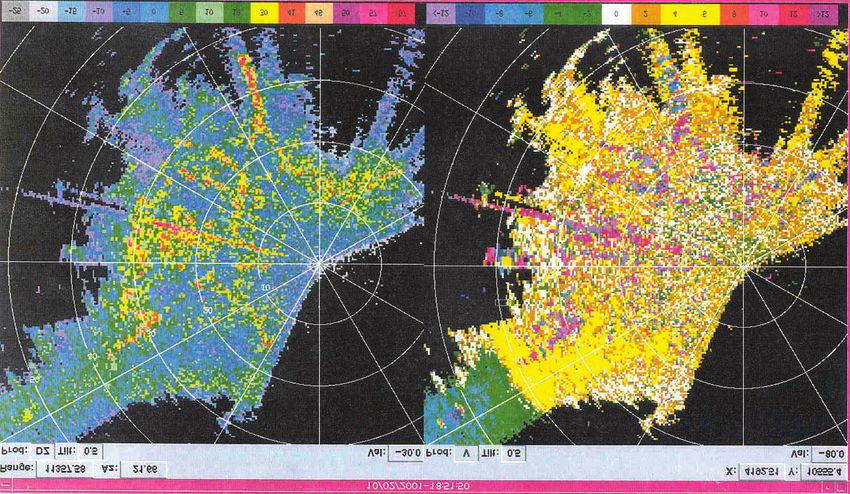
tive algorithms. The left-side image in Figure 5—plan At the completion of this acceptance testing at the
position indicator reflectivity and radial velocity images Monroney Center, the RDA engineering prototype
processed with the legacy algorithms—depicts a thun- will be deployed on an operational TDWR to dem-
derstorm gust front south of the radar. Strong range onstrate system performance and maintainability in
overlays from distant thunderstorms obscure major an operational environment. We anticipate that this
VOLUME 16, NUMBER 1, 2006 LINCOLN LABORATORY JOURNAL 15• weber
Advances in Operational Weather Radar Technology
Legacy Adaptive selection
60
36.0 36.0
35.8 35.8 40
Reflectivity (dBz)
Latitude (deg)
35.6 35.6
35.4 35.4 20
35.2 35.2
0
35.0 35.0
34.8 34.8
–20
34.6 34.6
–98.6 –98.2 –97.8 –97.4 –97.0 –96.6 –98.6 –98.2 –97.8 –97.4 –97.0 –96.6
Longitude (deg) Longitude (deg)
20
36.0 36.0 15
Radial velocity (m/sec)
35.8 35.8 10
Latitude (deg)
35.6 35.6 5
35.4 35.4 0
35.2 35.2 –5
35.0 35.0 –10
34.8 34.8 –15
34.6 34.6 –20
–98.6 –98.2 –97.8 –97.4 –97.0 –96.6 –98.6 –98.2 –97.8 –97.4 –97.0 –96.6
Longitude (deg) Longitude (deg)
FIGURE 5. Reflectivity images (upper) and radial velocity images (lower) of a strong gust-front passage, measured with the
FAA Monroney City TDWR in Oklahoma City. The left-side images were generated by using the legacy TDWR process-
ing algorithms that censor data (black areas in the radial velocity image) when distant thunderstorm overlays are –5 dB
or greater relative to the first-trip signal. The right-side images were generated by using the adaptive selection algorithm.
First-trip data obscuration from the range-overlaid weather is significantly reduced with this algorithm. Censoring criteria
for the algorithm are described elsewhere by J.Y.N. Cho [14].
demonstration will take place in Salt Lake City, Utah, ter are needed. The sidebar entitled “Low Reflectiv-
so that I&Q data can be collected to facilitate devel- ity Wind Shear” provides additional information on
opment of additional processing enhancements ad- this topic. These challenges have prevented the legacy
dressing the challenging environment at this site. Salt TDWR system from meeting its performance require-
Lake City is representative of several western U.S. ments at those sites, and have resulted in associated
TDWR sites (e.g., Denver, Las Vegas, Phoenix) where user dissatisfaction. The RDA prototype will be de-
improved capabilities for measuring radar signatures ployed to Salt Lake City in the summer of 2006, and
associated with very low cross-section, dry wind-shear the test program is anticipated to last for two years.
phenomena in the presence of strong ground clut- The FAA has programmed funding to deploy the
16 LINCOLN LABORATORY JOURNAL VOLUME 16, NUMBER 1, 2006• weber
Advances in Operational Weather Radar Technology
Velocity aliasing
30
20
Radial velocity (m/sec)
10
0
–10
–20
–30
Alternating radial dual PRF
Single PRF Multi-PRF
with phase code processing
FIGURE 6. Velocity images illustrating the de-aliasing performance of the enhanced RDA algorithms. Velocity estimates using
the legacy system single PRF waveforms (left) must be de-aliased by using image continuity-based post-processing algorithms
that have proven to be problematic. The middle and right images show de-aliased velocity fields generated by using the two
waveform classes employed in the enhanced RDA. Data are from the Monroney Center TDWR.
RDA replacement nationally during the period 2007
NEXRAD Algorithm Enhancements
through 2009. The components of the Laboratory-de-
veloped prototype system will be procured by the U.S. The triagency (NWS, FAA, and DoD) NEXRAD
Government (with COTS technology refreshes where Program Management Council has implemented
appropriate), then integrated and installed at all sites an ongoing improvement program to ensure that
by the FAA engineers from the Monroney Center. NEXRAD hardware, processors, and scientific algo-
In parallel, Lincoln Laboratory staff will continue to rithms remain current. Figure 7 shows a timeline for
develop and transition processing enhancements that major NEXRAD system hardware and processor up-
address operational needs at fielded TDWR sites. As grades. Each upgrade enables significant functional
noted, improved ground-clutter suppression and low- enhancements through the insertion of new or more
reflectivity wind-shear signature retrieval algorithms capable data processing algorithms. The first ma-
are expected to be fielded as a second major enhance- jor upgrade was the Open Radar Product Generator
ment following the range-Doppler ambiguity mitiga- (ORPG), the NEXRAD subsystem that processes ra-
tion improvements. Additional algorithm builds will dial-format reflectivity, mean Doppler velocity, and
be delivered as needed. Doppler spectrum width base data to generate meteo-
ORPG
Deployment
ORDA
Deployment
Development
Planned enhancements Dual polarization
Deployment
2001 2002 2003 2004 2005 2006 2007 2008 2009
Calendar year
FIGURE 7. Timeline for NEXRAD processor upgrades and hardware enhancements. The Open Radar Product Gen-
erator (ORPG) is already deployed, the Open Radar Data Acquisition (ORDA) subsystem is in the process of being
deployed, and the dual polarization upgrade is in development and on target for deployment in 2007.
VOLUME 16, NUMBER 1, 2006 LINCOLN LABORATORY JOURNAL 17• weber
Advances in Operational Weather Radar Technology
Low R e f l e c t i v i t y W i n d S h e a r
T he radar cross section per
unit volume for meteorologi-
cal targets is specified by the reflec-
radar cross section. Two factors
contribute to this circumstance.
First, the precipitation that
states is significantly lower than
the summertime background re-
flectivity in the eastern and central
tivity factor Z. Rayleigh scatterers forces the downdrafts and surface United States. This is due to the
(e.g., raindrops) contribute to the outflows responsible for low-alti- lower density of biological targets
reflectivity factor in proportion to tude wind shear may completely such as insects and in some cases
their number density and to their evaporate as it falls through the the soaring birds that feed on the
diameter raised to the sixth power. warm, dry boundary-layer char- insects. Figure A plots representa-
Reflectivity factors for meteoro- acteristic of the western United tive daily variations in near-sur-
logical targets vary from –40 dBz States during summer months. face clear-air reflectivity measured
for non-precipitating clouds to in Second, the background re- using the TDWRs at Dallas/Fort
excess of 70 dBz in severe storms flectivity of precipitation-free air Worth, Newark, and Las Vegas.
containing large hail. The mini- in the high plains and mountain The pronounced diurnal varia-
mum detectable signal (MDS) of
10
the Terminal Doppler Weather
Radar (TDWR) is –26 dBz at a 5
Newark (June)
Background reflectivity (dBz)
Las Vegas (June)
range of 10 km. For pulse-volume
Dallas/Fort Worth (June)
filling atmospheric targets, this 0
limit increases with range as R 2 (6
–5
dB per octave).
At most TDWR-equipped air- –10
ports, the wind-shear phenomena
–15
the system is designed to detect
occur in association with reflec- –20
tivity factors well above the MDS. = Sunrise = Sunset
However, at four western U.S. –25
0:00 4:00 8:00 12:00 16:00 20:00 0:00
airports—Denver, Salt Lake City, Local standard time
Las Vegas, and Phoenix—opera-
tionally significant wind shear FIGURE A. Representative daily cycles of the low-altitude clear-air reflectivity
may be associated with very low factor, measured with TDWRs at Dallas/Fort Worth, Newark, and Las Vegas.
rological products and disseminate these to NEXRAD of horizontally and vertically polarized signals. Radar
operational users. The Open Radar Data Acquisition meteorologists have shown that polarimetric measure-
(ORDA) subsystem is analogous to the enhanced ments can significantly improve quantitative rainfall
TDWR RDA described above and will support cor- estimates, discriminate between different hydrometer
responding improvements to the base data it feeds types (rain, snow hail, and graupel), identify non-me-
to ORPG. The dual-polarization upgrade will insert teorological biological targets (birds and insects), and
microwave components and a second receiving chain augment Doppler-filtering-based clutter suppression
to support simultaneous transmission and reception techniques [15].
18 LINCOLN LABORATORY JOURNAL VOLUME 16, NUMBER 1, 2006• weber
Advances in Operational Weather Radar Technology
(2) Estimation of near-surface
water-vapor content using the ‘re-
fractivity from clutter’ technique
[2] that does not rely on backscat-
Airport ter from atmospheric targets. The
leading edge of thunderstorm out-
flows (i.e., the gust front) should
be marked by a pronounced wa-
ter-vapor gradient. Examples of
this signature are shown elsewhere
[3].
(3) Comparison of signal Dop-
pler spectra on and immediately
Reflectivity Velocity adjacent to roadways to recognize
FIGURE B. Low-elevation-angle plan-position indicator data taken in precipi- and suppress spectral components
tation-free conditions from the TDWR at Las Vegas. The strong linear returns resulting from automobile traf-
exhibiting large non-zero Doppler velocities are from automobile traffic. fic. This capability will reduce or
eliminate the need for ‘road edit-
tion at Newark and Dallas/Fort Vegas is sited on elevated terrain ing’ maps currently used to censor
Worth reflects the activity levels east of the airport and as a result data over roadways, as illustrated
and vertical mixing of the biologi- is subject to strong returns from in Figure C.
cal targets. Note that background automobile traffic on roadways In addition to enhancing the
reflectivity at Las Vegas remains surrounding the airport. These re- performance of TDWR, the Lab-
below –10 dBz throughout most turns exceed the background at- oratory is working with the FAA
of the day. mospheric reflectivity factor, and to assess complementary sensing
Given the intrinsically low re- often fall outside the stop band of technologies. One promising ap-
flectivity of some wind-shear the TDWR’s high-pass Doppler proach is the use of a commercial-
events in these environments, clutter suppression filters. ly manufactured pulsed, infrared
challenges associated with ground- Techniques to be assessed to Doppler lidar that could be sited
clutter suppression are also exac- improve TDWR performance at on airport property. The lidar de-
erbated. As an example, Figure the ‘dry’ western sites include: tects returns from atmospheric
B is a plan position indicator re- (1) Range oversampling and aerosols, and normally has high
flectivity image, recorded dur- signal whitening [1] to reduce sig- signal-to-noise in the conditions
ing clear conditions with the Las nal parameter estimate variance at associated with ‘dry’ wind shear.
Vegas TDWR. The radar at Las low signal-to-noise ratios. In addition, the lidar’s very nar-
In the remainder of this section, we focus on the polarization upgrade to improve aviation weather sys-
Laboratory’s exploitation of ORPG to implement tems performance.
NEXRAD algorithm enhancements that significantly
improve the product quality of FAA systems that use Open Radar Product Generator
NEXRAD data. We anticipate that in the future Lab- Technology Insertion Approach
oratory engineers will interact with the multi-agency The ORPG—a COTS scientific workstation resident
NEXRAD enhancement community to develop ap- on each NWS Weather Forecast Office local area net-
plication algorithms that exploit ORDA and the dual- work—provides data input/output and meteorologi-
VOLUME 16, NUMBER 1, 2006 LINCOLN LABORATORY JOURNAL 19• weber
Advances in Operational Weather Radar Technology
row beam essentially eliminates attenuation, these events are well lidar would provide wind-shear
interference from ground targets. measured by the microwave radar detection performance that fully
The Laboratory analyzed data systems. meets requirements even in this
collected by this sensor in 2003 The Laboratory assisted the very challenging environment.
during wind-shear events in Den- FAA in collection of lidar and The FAA’s technology planning
ver [4], and showed that the lidar TDWR data in Las Vegas during organization is currently evaluat-
measurements complement those a three-week period in the sum- ing the technical and economic
from Doppler weather radar. Lidar mer of 2005. As an example of merits of pulsed Doppler lidar as
measurements of thunderstorm data collected, Figure C [5] com- an adjunct to Doppler radar at se-
outflows without precipitation pares TDWR and lidar measure- lect U.S. airports.
typically exhibited substantially ments of a gust front approaching
higher data quality than coinci- the airfield (the two sensors are References
1. S.M. Torres, C.D. Curtis, and J.R.
dent measurements with the Den- not collocated). The FAA analysis Cruz, “Pseudowhitening of Weather
ver TDWR or NEXRAD radars. of the Las Vegas data concludes Radar Signals to Improve Spectral Mo-
ment and Polarimetric Variable Esti-
Although wind shear occurring in that, if integrated, the comple- mates at Low Signal-to-Noise Ratios,”
precipitation was problematic for mentary sensing characteristics of IEEE Trans. Geosci. Remote Sens. 42
the lidar because of high signal the TDWR and pulsed Doppler (5), 2004, pp. 941–949.
2. E. Fabry, “Meteorological Value of
Ground Target Measurements by Ra-
dar,” J. Atmos. Oceanic. Technol. 21 (4),
2004, pp. 560–573.
3. T.M. Weckwerth, C.R. Pettet, F. Fab-
ry, S. Park, M.A. LeMone, and J.W.
Wilson, “Radar Refractivity Retrieval:
Validation and Application to Short-
term Forecasting,” J. Appl. Meteor. 44
(3), 2005, pp. 285–300.
4. G. Perras, “A Comparison of Coherent
Technologies, Inc. Wind Tracer Pulsed
Lidar Data to NEXRAD and Terminal
Doppler Weather Radar at the Denver
International Airport,” Lincoln Labo-
ratory Project Memorandum 43PM
Wx-0102 (13 Apr. 2005).
5. C. Keohan, K. Barr, and S.M. Han-
FIGURE C. Near-coincident radial velocity images of a gust-front passage at non, “Evaluation of Pulsed Lidar
Las Vegas on 30 July 2005, as measured with the airport’s TDWR (left) and a Wind Hazard Detection at Las Vegas
2 mm pulsed Doppler lidar (right). TDWR radial velocity censoring (shown in
International Airport,” 12th Conf. on
Aviation, Range and Aerospace Me-
black) is due to clutter and automobile returns, and it contributed to a missed teorology, Atlanta, Ga., 29 Jan.–2 Feb.
gust front (white dashed line). The lidar (right) detects the gust front (red 2006, http://ams.confex.com/ams/pdf
dashed line) approaching the airport from the east. Green indicates wind to- papers/105481.pdf.
ward the radar or lidar, while yellow indicates wind away from the radar or lidar.
cal processing for the associated NEXRAD. ORPG is data input/output details, system timing constraints,
currently implemented on a Sun Ultra 10 workstation; and system resource allocation issues so that externally
in 2007 it will be rehosted on a significantly faster developed scientific algorithms can be inserted by us-
PC-Linux computer to accommodate ever-increasing ing a plug-and-play paradigm.
processing demands. ORPG utilizes a Common Op- Under FAA sponsorship, a Laboratory team led
erations Development Environment (CODE) to fa- by Dave Smalley and Betty Bennett has been the
cilitate rapid algorithm technology insertion. CODE first NEXRAD algorithm development group to ex-
insulates ORPG algorithm developers from low-level tensively exploit the CODE paradigm. Laboratory
20 LINCOLN LABORATORY JOURNAL VOLUME 16, NUMBER 1, 2006• weber
Advances in Operational Weather Radar Technology
staff interacted with the NWS organization that de- multiple NEXRADs and displays resulting storm loca-
veloped CODE to fully understand how to utilize it. tion/intensity information to en route controllers on
We worked with the NEXRAD Radar Operations their radar scopes. In terminal airspace, the Integrated
Center—the radar network’s second-level engineer- Terminal Weather System (ITWS) displays NEXRAD
ing support organization—to establish a technol- composite reflectivity products in its long-range storm
ogy transfer process involving algorithm description, location/movement windows. Ground-clutter break-
software documentation, and system compatibility through, particularly during super-refractive or anom-
testing. Finally, we have interacted regularly with the alous propagation conditions, has been a significant
NEXRAD oversight organizations—the Technical Ad- data-quality issue in the FAA’s operational usage of
visory Committee responsible for algorithm scientific NEXRAD composite reflectivity products. The inten-
oversight and the System Resource Evaluation Com- sity and spatial extent of the clutter breakthrough have
mittee responsible for maintaining the overall integrity frequently been sufficient to present significant false
of NEXRAD processing resources—to coordinate the storm indications on the operational displays, thereby
insertion of Lincoln Laboratory–developed software reducing user confidence in the validity of the weather
and algorithms. presentation from WARP and ITWS.
An important infrastructure for enhanced algo- After providing an initial patch to the clutter edit-
rithm development and validation is a network of ing logic in the legacy composite reflectivity product,
ORPG workstations that we have connected to data Lincoln Laboratory developed a significantly more ro-
feeds from nine operational NEXRADs. Input base bust two-dimensional representation of storm intensi-
data from these radars are obtained in real time over ty—the high-resolution vertically integrated liquid wa-
Internet, Internet-2, and leased networks operated in ter (VIL) product. Inter-tilt reflectivity interpolation is
conjunction with other Lincoln Laboratory aviation first applied to fill data gaps; reflectivity is then con-
weather programs. The developmental ORPG net- verted to equivalent liquid water density and integrat-
work allows us to process these data in real time with ed over each range-azimuth vertical column to gener-
the enhanced algorithms developed by the Laboratory. ate the VIL field. A data quality-assurance module was
By continuously monitoring their output over extend- developed to precondition the base data input to the
ed periods of time, and at environmentally diverse lo- high-resolution VIL algorithm. This module exploits
cations, we are able to validate that the new algorithm signal discriminants in the spatial, spectral, and eleva-
implementations are robust and identify residual prod- tion angle domains to differentiate between ground-
uct-quality issues that may occur only infrequently. clutter breakthrough and meteorological echoes [16].
In addition, it detects and censors constant-power in-
ORPG Algorithm Enhancements terference introduced by the occasional inappropriate
Using this technology transfer process, we have suc- injection of calibration signals into operational data
cessfully implemented four major ORPG algorithm streams by NEXRAD maintenance personnel, and
enhancements and are completing development of a strobes when the antenna scans past the sun.
fifth. These are listed in Table 1, which also indicates The high-resolution VIL product has been shown
the FAA aviation weather systems that take advantage to convey the operational impact of storms much
of the improved products. more reliably than legacy NEXRAD composite reflec-
NEXRAD layer-average or layer-maximum com- tivity products [17]. Both the FAA WARP and ITWS
posite reflectivity products are two-dimensional repre- systems will transition their NEXRAD input to this
sentations of the measured precipitation field, gener- product in the future. Figure 8 compares the legacy
ated either by averaging the radar reflectivity values at composite-maximum reflectivity product to the high-
each range-azimuth cell over multiple elevation angle resolution VIL product.
tilts, or by choosing the maximum reflectivity across A corresponding high-resolution radar echo tops
the set of tilts. The FAA’s Weather and Radar Processor product developed by the Laboratory is also now field-
(WARP) mosaics composite reflectivity products from ed in the national NEXRAD network. This algorithm
VOLUME 16, NUMBER 1, 2006 LINCOLN LABORATORY JOURNAL 21• weber
Advances in Operational Weather Radar Technology
Table 1. NEXRAD Algorithm Enhancements and the FAA Weather Processing Systems
That Take Advantage of Them
Clutter- Data quality High-resolution High-resolution Machine-
edited assurance vertically enhanced intelligent
composite integrated echo tops gust-front
reflectivity liquid water algorithm
(VIL)
Weather and Radar Product Planned Planned Planned
Processor (WARP) in use use use use
Integrated Terminal Product Planned Planned Planned Potential
Weather System (ITWS) in use use use use use
Medium-Intensity Airport Product Product Product Potential
Weather System (MIAWS) in use in use in use use
ASR-9 Weather Systems Potential
Processor (WSP) use
Corridor Integrated Product Product Product Potential
Weather System (CIWS) in use in use in use use
remedies resolution deficiencies and biases present in Finally, the Laboratory-developed Machine Intel-
the legacy NEXRAD echo tops product [16]. Op- ligent Gust Front Algorithm (MIGFA)—developed
erational experience with this product’s application in originally for the FAA’s ASR-9 WSP and TDWR
the CIWS [7] shows that it reliably indicates whether wind-shear detection systems [18]—has been modified
thunderstorms block high-altitude jet routes, or con- to operate with NEXRAD signal parameters and will
versely, whether planes can fly over precipitations cells be inserted into the ORPG. The resulting automated
that might appear impenetrable on the basis of a two- detections of thunderstorm-generated gust fronts will
dimensional composite reflectivity or VIL product. allow FAA and DoD air traffic control personnel to
Composite reflectivity dBZ High-resolution VIL kg/m2
ND
0.05
5 0.19
0.36
18
0.66
30 1.23
2.11
41
3.63
46 6.23
9.89
50 15.7
25.0
57 36.7
54.0
80+
FIGURE 8. Comparison of the high-resolution vertically integrated liquid water (VIL) product (right) versus
a legacy composite reflectivity product (left). The VIL product provides higher spatial resolution and is not
as susceptible to single-tilt artifacts such as ground clutter or bright bands at the melting level. Data are
from the Norman, Oklahoma, NEXRAD during a severe weather outbreak on 3 May 1999.
22 LINCOLN LABORATORY JOURNAL VOLUME 16, NUMBER 1, 2006• weber
Advances in Operational Weather Radar Technology
anticipate gust-front impacts at smaller airports and were used to account for terrain effects. Karen Ander-
military airfields not equipped with the dedicated son and Jim Flavin in the Air Traffic Control Systems
wind-shear detection systems. group developed an iterative siting procedure to de-
MIGFA will also provide important input to au- lineate MPAR locations that duplicate current cover-
tomated thunderstorm forecasting algorithms [19] age. Figure 9 shows that 334 MPARs would provide
by detecting and tracking the surface convergence near-seamless airspace coverage above 5000 feet AGL,
boundaries that are preferred zones for new thun- replicating the national scale weather and aircraft cov-
derstorm development. Because of the complexity erage currently provided by the NEXRAD and ARSR
of this algorithm, and its computational resource re- networks. The figure also illustrates that these MPARs
quirements, MIGFA was selected by the NEXRAD would provide low-altitude, airport-area weather and
Radar Operations Center as the test algorithm for its aircraft surveillance functions that are today provided
upgraded, Linux-PC based ORPG platform. Lincoln by TDWR and ASR-9 or ASR-11 terminal radars.
Laboratory engineers are working closely with the Ra- Approximately half of the MPARs are terminal-area
dar Operations Center to quantify MIGFA’s processor gap fillers providing range-limited coverage under-
and memory usage on this platform, and to expose neath the radar horizon of the national-scale network.
portability and operational stability issues. These would be smaller-aperture, lower-cost radars
employing the same scalable technology as the full-
Next-Generation Multifunction Radar Study sized MPAR [20].
Current U.S. weather and aircraft surveillance radar
networks vary in age from ten to more than forty years. MPAR Configuration
Ongoing sustainment and upgrade programs can keep If the reduced numbers of MPARs required and their
these networks operating in the near to mid term, single architecture are to produce significant future
but the responsible agencies (FAA, NWS, and DoD/ cost savings, the acquisition costs of the active elec-
DHS) recognize that large-scale replacement activities tronically scanned array radars must be at least compa-
must begin during the next decade. In 2005, the FAA rable to the mechanically scanned radars they replace.
asked Lincoln Laboratory to evaluate the technology To define the technical parameters of the required
issues and cost trades associated with a replacement MPAR and estimate its costs, we developed a concep-
strategy involving multifunction radars utilizing active tual radar configuration and have commenced detailed
electronically scanned arrays. design of prototype components that address its key
Cost considerations are a key element of this study. technical challenges.
The current operational ground radar network is com- Figure 10 shows a high-level depiction of the
posed of seven distinct radar systems with separate conceptual MPAR architecture. Table 2 lists key pa-
government program offices, engineering support or- rameters. The 2.7 to 2.9 GHz S-band allocation for
ganizations, and logistics lines. A single, national mul- the current NEXRAD and ASR networks provides
tifunction phased-array radar (MPAR) network could a compromise between sensitivity requirements for
reduce life-cycle costs by consolidating these support meteorological targets (whose cross section increases
functions. The total number of deployed radars could with decreasing wavelength) and challenges associ-
also be reduced, since the airspace coverages from to- ated with precipitation-induced signal attenuation,
day’s radar networks overlap substantially. range-Doppler ambiguities, and precipitation clutter
Today, a total of 510 weather and primary aircraft rejection for the aircraft surveillance function. All of
surveillance radars operate in the CONUS. To quan- these latter challenges are increasingly problematic at
tify the potential reduction in radar numbers, Steve shorter wavelengths. In addition, an S-band active ar-
Maloney in the Weather Sensing group at Lincoln ray can exploit the low-cost, COTS component base
Laboratory developed a three-dimensional database developed for the consumer wireless device market.
that defines the current airspace coverage of these net- Maintaining low costs for active electronically scanned
works. High-resolution digital terrain elevation data arrays dictates the use of commercially available, low-
VOLUME 16, NUMBER 1, 2006 LINCOLN LABORATORY JOURNAL 23• weber
Advances in Operational Weather Radar Technology
Current Radar coverage Multifunction radar coverage
510 total radars (seven unique types) 334 total radars (one type)
50º
50º N
N
40º 40º
N N
1000 ft AGL
30º
N
30º
N
20º 20º
N N
120º 70º W 120º
W 110º W 80º W W 70º W
100º W 90º W 110º W
100º W 90º W 80º W
50º
N
50º
N
40º
N
40º
N
5000 ft AGL
30º
N
30º
N
20º
N
20º
N
120º
W 70º W
110º W
100º W 90º W 80º W 120º 70º W
W
110º W
100º W 90º W 80º W
FIGURE 9. Airspace coverage comparisons between current U.S. operational radar networks (left), consisting of 510
radars of seven types (ASR-9, ASR-11, ARSR-1/2, ARSR-3, ARSR-4, NEXRAD, and TDWR), and the conceptual multi-
function phased-array radar (MPAR) network (right), consisting of 334 radars of a single type. Coverage at 1000 feet and
5000 feet above ground level (AGL) is depicted for both networks.
peak-power transmit amplifiers (1 to 10 W). This in Signals are transmitted and received independently
turn requires the use of long (up to 50 msec) transmit- in each of these sub-bands. Channelized TR elements
ted pulses to achieve necessary energy on target. Pulse with independent phase shifters and attenuators for
compression to a 1 msec equivalent pulse length pro- each sub-band, and a sub-array beamformer architec-
vides the necessary range resolution (150 m). ture [21], allow for the transmission of independently
A four-faced planar array is assumed, although the steered transmit beams for each sub-band and the dig-
transmit/receive (TR) element count can most likely ital formation of associated receive beam clusters.
be reduced by using cylindrical or quasi-hemispherical This architecture supports efficient allocation of
array geometries. Angular resolution (1° or less) and energy to the three surveillance functions, as depicted
power-on-target requirements are set by the weather in Figure 11. For each function, the transmit beam is
surveillance function. This dictates an aperture size of spoiled as appropriate to balance energy-on-target and
eight meters and an associated TR-element count of volume-scan update requirements. For terminal-area
20,000 per face (80,000 total). Multifunction aircraft aircraft surveillance, a 1° × 5° transmit beam provides
and weather surveillance capability is attained by al- more than adequate energy density while supporting
locating three 1 MHz sub-bands within the 2.7 to 2.9 the five-second volume-scan update rate required for
GHz interval to the three requisite surveillance func- tracking aircraft in this domain. For weather surveil-
tions: (1) terminal area (0 to 60 nmi) aircraft surveil- lance of low cross-section clear-air phenomena, maxi-
lance; (2) long-range (0 to 250 nmi) aircraft surveil- mum sensitivity must be maintained, dictating the
lance; and (3) weather surveillance (0 to 250 nmi). transmission of full-resolution (1° × 1°) beams. Long-
24 LINCOLN LABORATORY JOURNAL VOLUME 16, NUMBER 1, 2006You can also read