GEOTECHNICAL DESIGN MANUAL ABUTMENTS, RETAINING WALLS, AND REINFORCED SLOPES - NYSDOT Geotechnical Design Manual - New York State Department of ...
←
→
Page content transcription
If your browser does not render page correctly, please read the page content below
GEOTECHNICAL DESIGN MANUAL

                      CHAPTER 17
               ABUTMENTS, RETAINING WALLS,
                 AND REINFORCED SLOPES

NYSDOT Geotechnical      Page 17-1      January 18, 2022
Design Manual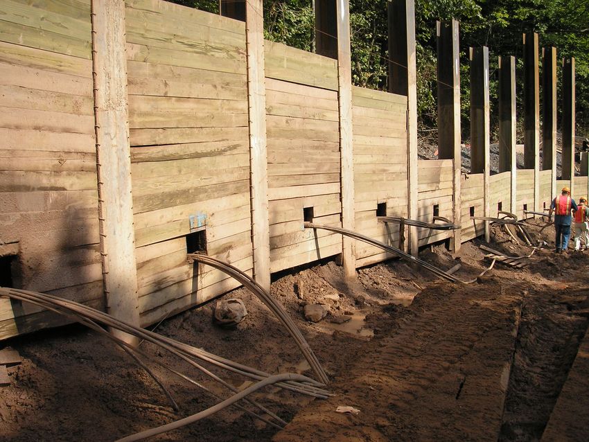
(Intentionally left blank)

NYSDOT Geotechnical        Page 17-2               January 18, 2022
Design Manual
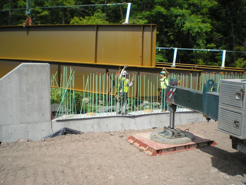
Table of Contents

17.1   INTRODUCTION AND DESIGN STANDARDS ....................................................... 17-5

17.2   OVERVIEW OF WALL CLASSIFICATIONS AND DESIGN PROCESS FOR
       WALLS .......................................................................................................................... 17-6

17.3   REQUIRED INFORMATION ...................................................................................... 17-9
       17.3.1 Geotechnical Data Needed for Abutment, Retaining Wall and Reinforced Slope
              Design ............................................................................................................. 17-9
       17.3.2 Site Reconnaissance ...................................................................................... 17-10
       17.3.3 Field Exploration Requirements ................................................................... 17-10
       17.3.4 Groundwater ................................................................................................. 17-11
       17.3.5 Wall Backfill ................................................................................................. 17-11

17.4   GENERAL DESIGN REQUIREMENTS ................................................................... 17-11
       17.4.1 Design Methods ............................................................................................ 17-11
       17.4.2 Back-to-Back MSES Walls........................................................................... 17-12
       17.4.3 Walls on Slopes............................................................................................. 17-12
       17.4.4 Minimum Embedment .................................................................................. 17-12
       17.4.5 Proprietary Fill Type Retaining Wall Height Limitations ............................ 17-12
       17.4.6 Engineering Considerations .......................................................................... 17-14
       17.4.7 Serviceability Requirements ......................................................................... 17-18
       17.4.8 Active, Passive, At-Rest Earth Pressures ...................................................... 17-19
       17.4.9 Surcharge Loads............................................................................................ 17-20
       17.4.10 Seismic Earth Pressures .............................................................................. 17-21
       17.4.11 Liquefaction ................................................................................................ 17-21
       17.4.12 Overall Stability .......................................................................................... 17-21
       17.4.13 Wall Drainage ............................................................................................. 17-21
       17.4.14 Utilities........................................................................................................ 17-22
       17.4.15 Guardrail and Barrier .................................................................................. 17-22

17.5   WALL TYPE SPECIFIC DESIGN REQUIREMENTS ............................................. 17-22
       17.5.1 Abutments, Wingwalls & Gravity Type Cantilever Walls ........................... 17-22
              17.5.1.1 Integral Abutments......................................................................... 17-23
              17.5.1.2 Pile Supported Abutments Combined with Fill Type Retaining
                       Walls .............................................................................................. 17-25
              17.5.1.3 Geosynthetic Reinforced Soil-Integrated Bridge System
                       Abutments ...................................................................................... 17-25
              17.5.1.4 Precast Concrete Wingwalls .......................................................... 17-26
              17.5.1.5 Gravity Type Cast-In-Place Concrete Cantilever Walls ................ 17-26
       17.5.2 Nongravity Cantilever and Anchored Walls ................................................. 17-26
              17.5.2.1 Sheeting Walls ............................................................................... 17-27
              17.5.2.2 Soldier Pile and Lagging Walls ..................................................... 17-28
              17.5.2.3 Anchored/Braced Walls ................................................................. 17-30
NYSDOT Geotechnical                                     Page 17-3                                            January 18, 2022
Design Manual
Table of Contents

                    17.5.2.4 Cofferdams ..................................................................................... 17-32
                              17.5.2.4.1 Tremie Seals.................................................................. 17-37
                    17.5.2.5 Permanent & Temporary Grouted Tieback Anchor....................... 17-38
                              17.5.2.5.1 Inspection ...................................................................... 17-40
                    17.5.2.6 Deadman Anchor ........................................................................... 17-41
       17.5.3       Internally Stabilized Fill Walls ..................................................................... 17-42
                    17.5.3.1 Mechanically Stabilized Earth System (MSES) Walls .................. 17-42
                              17.5.3.1.1 Live Load Considerations for MSES Walls................. 17-45
                              17.5.3.1.2 Backfill Considerations for MSES Walls .................... 17-46
                              17.5.3.1.3 Abutments Supported on Piles Through an MSES ...... 17-47
                    17.5.3.2 Mechanically Stabilized Wall System (MSWS) Walls ................. 17-48
                    17.5.3.3 Geosynthetically Reinforced Soil System (GRSS) Walls ............. 17-52
       17.5.4       Geosynthetically Reinforced Soil System (GRSS) Slopes ........................... 17-53
                    17.5.4.1 Failure Modes for Geosynthetic Reinforcement Design ................ 17-54
                    17.5.4.2 Safety Factors and Resistance Factors ............................................ 17-55
                    17.5.4.3 Design of Reinforced Slopes .......................................................... 17-55
                    17.5.4.4 Reinforced Slope Facings ............................................................... 17-56
                    17.5.4.5 Reinforced Slope Drainage ............................................................. 17-58
                    17.5.4.6 Reinforced Slope Construction ....................................................... 17-58
       17.5.5       Prefabricated Wall Systems (PWS) .............................................................. 17-59
       17.5.6       Geocell Walls ................................................................................................ 17-60
       17.5.7       Gabion Walls ................................................................................................ 17-61
                    17.5.7.1 Applications .................................................................................... 17-63
       17.5.8       Soil Nail Walls .............................................................................................. 17-64
                    17.5.8.1 Soil Nail Wall Concepts and Components...................................... 17-65

17.6   EXCAVATION SUPPORT AND COFFERDAM REQUIREMENTS AND
       DETAILS ..................................................................................................................... 17-68
       17.6.1 Excavation Support Guidelines..................................................................... 17-68
       17.6.2 Temporary Excavation Support Requirements for Railroad Tracks............. 17-68
       17.6.3 Cofferdam and Waterway Diversion Guidelines .......................................... 17-72

17.7   REFERENCES ............................................................................................................ 17-72

NYSDOT Geotechnical                                     Page 17-4                                          January 18, 2022
Design Manual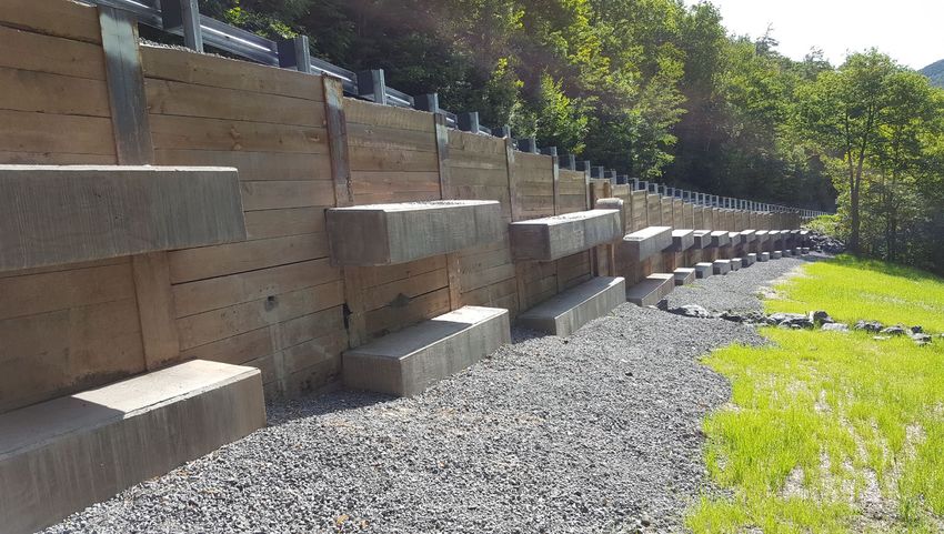
CHAPTER 17
                   Abutments, Retaining Walls, and Reinforced Slopes

17.1 INTRODUCTION AND DESIGN STANDARDS

Abutments for bridges have components of both foundation design and wall design. This chapter
addresses the earth pressures acting on the abutments as well as retaining walls and reinforced
slopes. Retaining walls and reinforced slopes are typically included in projects to minimize
construction in wetlands, to widen existing facilities, and to minimize the amount of right of way
needed in urban environments. Projects modifying existing facilities often need to modify or
replace existing retaining walls or widen abutments for bridges.

Retaining walls and reinforced slopes have many benefits associated with their use.
Unfortunately, there also tends to be confusion regarding when they should be incorporated into
a project, what types are appropriate, how they are designed, who designs them, and how they
are constructed. The roles and responsibilities of the various NYSDOT offices and those of the
Department’s consultants further confuse the issue of retaining walls and reinforced slopes, as
many of the roles and responsibilities overlap or change depending on the wall type. All
abutments, retaining walls, and reinforced slopes within NYSDOT Right-of-Way or whose
construction is administered by NYSDOT shall be designed in accordance with the following
documents:

       1.   NYSDOT Geotechnical Design Manual (GDM)
       2.   NYSDOT Bridge Manual
       3.   NYSDOT Highway Design Manual
       4.   NYSDOT LRFD Bridge Design Specifications (AASHTO with NYSDOT revisions)

The most current versions or editions of the above referenced manuals including all interims or
design memoranda modifying the manuals shall be used. In the case of conflict or discrepancy
between manuals, the following hierarchy shall be used: Those manuals listed first in the list
above shall supersede those listed lower in the list.

The following manuals, including the most current versions available, provide additional design
and construction guidance for retaining walls and reinforced soil slopes and should be considered
supplementary to the NYSDOT GDM and the manuals and design specifications listed above:

   •    NYS Department of Transportation, Geotechnical Engineering Bureau, Geotechnical
        Design Procedure for Flexible Wall Systems, GDP-11, most current version.

   •    Berg, R. R., Christopher, B. R., and Samtani, N. C., 2009, Design and Construction of
        Mechanically Stabilized Earth Walls and Reinforced Soil Slopes GEC-011, No. FHWA-
        NHI-10-024, U.S. Department of Transportation, Federal Highway Administration, 306
        pp.

   •    Munfakh, George A., Samtani, Naresh C., Castelli, Raymond J., Wang, Jaw-Nan, 1999,
        Earth Retaining Structures, Reference Manual, FHWA-NHI-99-025, U.S. Department of
        Transportation, Federal Highway Administration, 444 pp.

NYSDOT Geotechnical                      Page 17-5                           January 18, 2022
Design Manual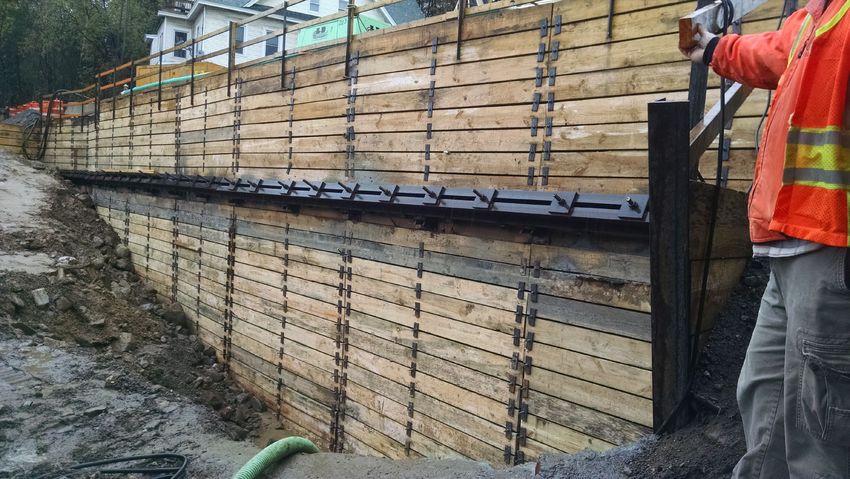
CHAPTER 17
                 Abutments, Retaining Walls, and Reinforced Slopes

   •   Lazarte, C. A., Robinson, H., Gomez, J. E., Baxter, A., Cadden, A., Berg, R., 2015,
       Geotechnical Engineering Circular No. 7, Soil Nail Walls-Reference Manual, FHWA-
       NHI-14-007, U.S. Department of Transportation, Federal Highway Administration, 425
       pp.

   •   Samtani, N. C., and Nowatzki, E. A., 2006, Soils and Foundations, Reference Manual-
       Volumes I and II, FHWA-NHI-06-088/089, Washington, D.C., National Highway
       Institute Publication, Federal Highway Administration.

   •   Sabatini, P. J., Pass, D. G., and Bachus, R. C., 1999, Geotechnical Engineering Circular
       No. 4, Ground Anchors and Anchored Systems, FHWA-IF-99-015, U.S. Department of
       Transportation, Federal Highway Administration, 281 pp.

   •   PTI Prestressed Rock and Soil Anchor Committee, 1996, Recommendations for
       Prestressed Rock and Soil Anchors, Post Tensioning Institute, 70 pp.

17.2 OVERVIEW OF WALL CLASSIFICATIONS AND DESIGN PROCESS FOR
WALLS

The various walls and wall systems can be categorized based on their intended functional life:
permanent, temporary, and interim.

   1. Permanent: A permanent system provides a structural support function for the life of the
      facility.
   2. Temporary: A temporary system is designed to provide structural support during
      construction, and is removed when construction is complete.
   3. Interim: An interim system is identical to a temporary system in function, except it
      remains in place (although it no longer provides a structural function) because its removal
      would be detrimental to the finished work.

The classification of retaining wall systems is based on the basic geotechnical mechanism used
to resist lateral loads and the construction method used for the installation of the wall. The
following are definitions used to classify retaining wall systems:

   1. Externally Stabilized Structures: Externally stabilized structures rely on the integrity of
      wall elements (with or without braces, struts, wales and/or tiebacks or anchors) to both
      resist lateral loads and prevent raveling or erosion of the retained soil.
   2. Internally Stabilized Structures: Internally stabilized structures rely on friction developed
      between closely-spaced reinforcing elements and the backfill to resist lateral soil
      pressure. A separate, non-structural element (facing, erosion control mat and/or
      vegetation) is attached to prevent raveling or erosion of the retained soil.
   3. Fill Type Retaining Walls: Retaining structures constructed from the base of the wall to
      the top (i.e. “bottom-up” construction).
NYSDOT Geotechnical                      Page 17-6                           January 18, 2022
Design Manual
CHAPTER 17
                 Abutments, Retaining Walls, and Reinforced Slopes

   4. Cut Type Retaining Walls: Retaining structures constructed from the top of the wall to
      the base (i.e. “top-down” construction).

An overview of the classification of retaining wall systems is provided in Table 17-1. The table
provides a breakdown of available retaining wall systems, its associated method of construction,
means of stability, design requirements and constraints (e.g. typical height range, maximum wall
height).

NYSDOT Geotechnical                     Page 17-7                          January 18, 2022
Design Manual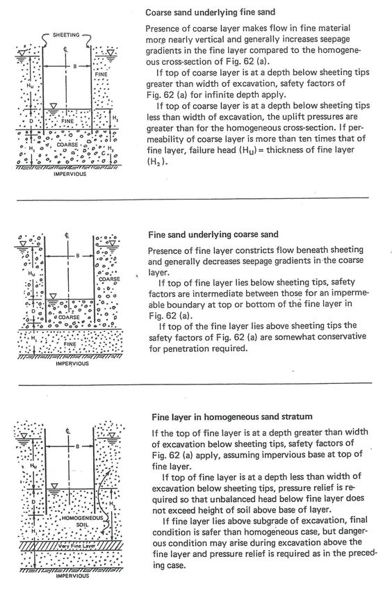
CHAPTER 17
                    Abutments, Retaining Walls, and Reinforced Slopes

  Wall               Wall            Construction          Wall                                       Typical
                                                                               Design
  Class              Type               Type              Group                                   Height Limit (ft)

                                                                       Designed & detailed in            15
             Sheeting Walls          Cut Wall       Cantilever
                                                                       Contract Plans.
             Soldier Pile &                                            Designed & detailed in            20
                                     Cut Wall       Cantilever
             Lagging Walls                                             Contract Plans.
                                                    Deadman            Designed & detailed in
                                                                                                         25
                                                    Anchors            Contract Plans.

Externally                                                             Designed & detailed in
Stabilized                                          Grouted Single     Contract Plans.
                                                                                                         30
Cut                                                 Level Tiebacks     Tieback designed by
             Anchored and Braced                                       Contractor’s Designer
Structures
             Walls (Sheeting or
                                 Cut Wall                              Designed & detailed in
             Soldier Pile &
             Lagging Walls)                         Grouted Multiple   Contract Plans.
                                                                                                     Unlimited
                                                    Level Tiebacks     Tieback designed by
                                                                       Contractor’s Designer
                                                    Braced Walls
                                                                       Designed & detailed in
                                                    (Wales and                                       Unlimited
                                                                       Contract Plans.
                                                    Struts)
                                                                       Detailed in contract.
                                                    Precast Cantilever
                                                                       Designed by Contractor’s          15
                                                    Wall
             Cantilever Wall         Fill Wall                         Designer
                                                    CIP Cantilevered   Designed & detailed in
                                                                                                         25
Externally                                          Wall               Contract Plans.
Stabilized                                                             Designed & detailed in
Fill         Gravity Wall            Fill Wall      Gabion                                               20
                                                                       Contract Plans.
Structures
                                                                       Detailed in Contract
                                                                       Plans.                           35
             Fill Type Retaining                    Prefabricated Wall
                                     Fill Wall                         Designed by Contractor’s      or as per
             Wall                                   System (PWS)
                                                                       Designer (Proprietary       Approved List
                                                                       Wall).
                                                                       Detailed in Contract
                                                    Mechanically       Plans.
                                     Fill Wall      Stabilized Earth   Designed by Contractor’s          65
                                                    System (MSES)      Designer (Proprietary
                                                                       Wall).
Internally
             Fill Type Retaining                                       Detailed in Contract
Stabilized
             Wall                                   Mechanically       Plans.
Fill
                                     Fill Wall      Stabilized Wall    Designed by Contractor’s          65
Structures
                                                    System (MSWS)      Designer (Proprietary
                                                                       Wall).
                                                    Geosynthetically
                                                                       Designed & detailed in
                                     Fill Wall      Reinforced Soil                                      65
                                                                       Contract Plans.
                                                    System (GRSS)
Internally                                                             Detailed in Contract
Stabilized                           Cut Wall       Soil Nail Wall     Plans.
             Soil Nail Wall System                                                                       65
Cut                                                 System             Designed by Contractor’s
Structures                                                             Designer

                       Table 17-1 Classification of Retaining Wall Systems

NYSDOT Geotechnical                              Page 17-8                               January 18, 2022
Design Manual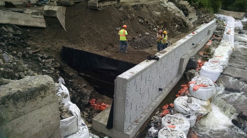
CHAPTER 17
                 Abutments, Retaining Walls, and Reinforced Slopes

Several proprietary wall systems have been extensively reviewed by the Geotechnical
Engineering Bureau, Materials Bureau and Office of Structures. This review has resulted in
NYSDOT creating a Fill Type Retaining Wall Approved List. The design procedures and wall
details for these preapproved wall systems shall be in accordance with the approved design
procedure, this manual (NYSDOT GDM) and other manuals specifically referenced herein as
applicable to the type of wall being designed. In addition, NYSDOT Standard Sheet 554-01
Proprietary Fill Type Retaining Walls provides installation requirements. These preapproved
design procedures and details allow the manufacturers to competitively bid a project without
having a detailed wall design provided in the contract plans. Note that proprietary wall
manufacturers may produce several retaining wall options, and not all options from a given
manufacturer have been preapproved. Only the wall systems appearing on the Approved List can
be used on NYSDOT projects.

17.3 REQUIRED INFORMATION

17.3.1 Geotechnical Data Needed for Abutment, Retaining Walls and Reinforced
Slope Design

The project requirements, site, and subsurface conditions should be analyzed to determine the
type and quantity of information to be developed during the geotechnical investigation. It is
necessary to:

   •   Identify areas of concern, risk, or potential variability in subsurface conditions.
   •   Develop likely sequence and phases of construction as they may affect abutment,
       retaining wall and reinforced slope selection.
   •   Identify design and constructability requirements or issues such as:
           – Surcharge loads from adjacent structures
           – Backslope and toe slope geometries
           – Right of way restrictions
           – Materials sources
           – Easements
           – Excavation limits
           – Wetlands
           – Construction Staging
   •   Identify performance criteria such as:
           – Tolerable settlements for the abutments, retaining walls and reinforced slopes
           – Tolerable settlements of structures or property being retained
           – Impact of construction on adjacent structures or property
           – Long-term maintenance needs and access
   •   Identify engineering analyses to be performed such as:
           – Bearing resistance
           – Settlement
           – Global stability
           – Internal stability
           - Deep Foundation analyses
           - Soil/Structure interaction
   •   Identify engineering properties and parameters required for these analyses.
NYSDOT Geotechnical                     Page 17-9                           January 18, 2022
Design Manual
CHAPTER 17
                   Abutments, Retaining Walls, and Reinforced Slopes

    •   Identify the number of tests/samples needed to estimate engineering properties.

    NYSDOT GDM Chapter 6 covers requirements for how the results from the field
investigation, the field testing, and laboratory testing are to be used to establish properties for
design. The specific tests and field investigation requirements needed for foundation design are
described in the following sections.

17.3.2 Site Reconnaissance

For each abutment, retaining wall, and reinforced slope, the Departmental Geotechnical Engineer
should perform a site review and field reconnaissance. The Departmental Geotechnical Engineer
should be looking for specific site conditions that could influence design, construction, and
performance of the retaining walls and reinforced slopes on the project. This type of review is
best performed once survey data has been collected for the site and digital terrain models, cross-
sections, and preliminary wall profiles have been generated by the Project Designer. In addition,
the Departmental Geotechnical Engineer should have access to detailed plan views showing
existing site features, utilities, proposed construction, and right-of-way limits. With this
information, the Departmental Geotechnical Engineer can review the wall/slope locations
making sure that survey information agrees reasonably well with observed site topography. The
Departmental Geotechnical Engineer should observe where utilities are located, as they will
influence where field exploration can occur and they may affect design or constructability. The
Departmental Geotechnical Engineer should look for indications of soft soils or unstable ground.
Items such as hummocky topography, seeps or springs, pistol butted trees, and scarps, either old
or new, need to be investigated further. Vegetative indicators such as equisetum (horsetails), cat
tails, black berry, or alder can be used to identify soils that are wet or unstable. A lack of
vegetation can also be an indicator of recent slope movement. In addition to performing a basic
assessment of site conditions, the Departmental Geotechnical Engineer should also be looking
for existing features that could influence design and construction such as nearby structures,
surcharge loads, and steep back or toe slopes. This early in design, it is easy to overlook items
such as construction access, materials sources, and limits of excavation. The Departmental
Geotechnical Engineer needs to be cognizant of these issues and should be identifying access and
excavation issues early, as they can affect permits and may dictate what wall type may or may
not be used.

17.3.3 Field Exploration Requirements

A soil investigation and geotechnical reconnaissance is critical for the design of all abutments,
retaining walls, or reinforced slopes. The stability of the underlying soils, their potential to settle
under the imposed loads, the usability of any existing excavated soils for wall/reinforced slope
backfill, and the location of the ground water table are determined through the geotechnical
investigation. All abutments, retaining walls and reinforced slopes regardless of their height
require an investigation of the underlying soil/rock that supports the structure. Abutments shall
be investigated like other bridge piers in accordance with NYSDOT GDM Chapter 11.

Explorations consisting of geotechnical borings, test pits, or a combination thereof shall be
performed at each abutment, wall or slope location, in accordance with the requirements in
NYSDOT GDM Chapter 4. Geophysical testing may be used to supplement the subsurface
NYSDOT Geotechnical                         Page 17-10                            January 18, 2022
Design Manual
CHAPTER 17
Abutments, Retaining Walls, and Reinforced Slopes
exploration. If the geophysical testing is done as a first phase in the exploration program, it can
also be used to help develop the detailed plan for second phase exploration. As a minimum, the
subsurface exploration and testing program should obtain information to analyze foundation
stability and settlement with respect to:
• Geological formation(s).
• Location and thickness of soil and rock units.
• Engineering properties of soil and rock units, such as unit weight, shear strength and
compressibility.
• Ground water conditions.
• Ground surface topography.
• Local considerations (e.g., liquefiable, expansive soil deposits, underground voids from
solution weathering or mining activity, or slope instability potential).
In areas underlain by highly variable soil deposits and/or rock formations, it will likely be
necessary to perform more investigation to capture variations in soil and/or rock type across the
site area.
17.3.4 Groundwater
One of the principal goals of a good field reconnaissance and field exploration program is to
accurately characterize the groundwater in the project area. Groundwater affects the design,
performance, and constructability of project elements. Installation of piezometer(s) (see
NYSDOT GDM Chapter 23) and monitoring is sometimes necessary to adequately define
groundwater conditions.
17.3.5 Wall Backfill
One of the primary components of all fill walls is the backfill soil. NYSDOT Standard
Specifications provide requirements for Select Structural Fill. This granular material is used for
backfill for most retaining wall systems due to its strength and free-draining properties.
Mechanically stabilized earth systems incorporate a specialized backfill material to ensure long-
term performance of the embedded reinforcing elements. See Section 17.5.3.1.2 for discussion
regarding MSES backfill material.
17.4 GENERAL DESIGN REQUIREMENTS
17.4.1 Design Methods
The NYSDOT LRFD Bridge Design Specifications shall be used for all abutments and retaining
walls addressed therein. The walls shall be designed to address all applicable limit states
(strength, service, and extreme event).
Many FHWA manuals under the GEC series have been updated to LRFD methodologies and the
most current version should be used for retaining wall and reinforced slope designs.
NYSDOT Geotechnical Page 17-11 January 18, 2022
Design ManualCHAPTER 17
Abutments, Retaining Walls, and Reinforced Slopes
Acceptable design methodology and theory for the geotechnical design of flexible cantilevered
or anchored retaining walls is provided in NYSDOT Geotechnical Design Procedure for Flexible
Wall Systems, GDP-11.
Rock walls, reinforced slopes, and soil nail walls are not specifically addressed in the NYSDOT
LRFD Bridge Design Specifications, and shall be designed in accordance with this manual.
17.4.2 Back-to-Back MSES Walls
For back-to-back MSES walls, the FHWA manual entitled “Design and Construction of
Mechanically Stabilized Earth Walls and Reinforced Soil Slopes” by Berg, et al. (2009), shall be
used as the basis for design for those aspects of the design not covered in the NYSDOT LRFD
Bridge Design Specifications and the NYSDOT GDM.
17.4.3 Walls on Slopes
Bearing resistance for footings on slopes and overall stability requirements in the NYSDOT
LRFD Bridge Design Specifications shall be met.
Table C11.10.2.2-1 in the NYSDOT LRFD Bridge Design Specifications should be used as a
starting point for determining the minimum wall face embedment of MSES walls when the wall
is located on a slope. Use of a smaller embedment must be justified based on slope geometry,
potential for removal of soil in front of the wall due to erosion, future construction activity, etc.,
and external and global wall stability considerations.
For soldier pile and lagging walls on slopes, the design height should be above a stable design
slope.
17.4.4 Minimum Embedment
All abutments and cantilever walls with footings should have a minimum embedment in
accordance with the NYSDOT Bridge Manual Section 11.1.8 Footing Depth. All other walls
shall meet the minimum embedment criteria in NYSDOT LRFD Bridge Design Specifications.
The final embedment depth required shall be based on geotechnical bearing and stability
requirements provided in the NYSDOT LRFD Bridge Design Specifications, as determined by
the Geotechnical Engineer (see also NYSDOT GDM Section 17.4.3).
In situations where scour can occur in front of the wall, the bottom of the footing, panel, or
lagging shall meet the minimum embedment requirements relative to the scour elevation in front
of the wall. A minimum embedment of 2 feet below scour elevation shall be used, unless a
greater depth is specified.
17.4.5 Proprietary Fill Type Regaining Wall Height Limitations
Proprietary fill type retaining wall systems that are preapproved through NYSDOT have limiting
heights for unreinforced applications as noted on the Fill Type Retaining Wall Approved List. In
NYSDOT Geotechnical Page 17-12 January 18, 2022
Design ManualCHAPTER 17
Abutments, Retaining Walls, and Reinforced Slopes
addition, note that no fill type retaining walls will be allowed for supporting abutments on spread
footings.
NYSDOT Geotechnical Page 17-13 January 18, 2022
Design ManualCHAPTER 17
Abutments, Retaining Walls, and Reinforced Slopes
17.4.6 Engineering Considerations
Each type of wall is suitable for different situations. When choosing a wall type, keep in mind the site conditions, construction time, the area
that each wall encompasses, and the effects of site conditions on the wall.
Table 17-2 summarizes the engineering characteristics associated with each wall type.
Relative Sensitivity to
Approx.
Wall Type Construction Differential Advantages Disadvantages
Base Width
Time Settlement
Cantilever Long 0.6 to 0.7 x High Well established performance characteristics Long construction time, formwork and curing
Concrete Wall Wall Height time are required
Durability
Wall is rigid and sensitive to differential
Many available aesthetic finishes settlements
Prefabricated Short 0.5 to 0.7 x Low Rapid construction that does not require Since components are prefabricated, on-site
(Modular) Wall Wall Height specialized equipment adjustments are difficult
System
Gabion Wall Short 0.7 x Wall Low Rapid construction that does not require Aesthetics may be perceived as poor
Height specialized equipment
Wire baskets are susceptible to corrosion and/or
damage
NYSDOT Geotechnical Page 17-14 January 18, 2022
Design ManualCHAPTER 17
Abutments, Retaining Walls, and Reinforced Slopes
Relative Sensitivity to
Approx.
Wall Type Construction Differential Advantages Disadvantages
Base Width
Time Settlement
MSES/MSWS Medium 0.7 x Wall Low Many available aesthetic finishes Use of metallic reinforcement requires backfill
Wall Height that meets electrochemical requirements for
Wall system is flexible, able to tolerate corrosion protection that is not readily available
differential settlements in all parts of NY state
Wall system has many components that require
careful inspection during construction
GRSS Wall Medium 0.7 x Wall Low Can be designed with a vegetated face Without vegetated face, may not be aesthetically
Height pleasing
Wall system is flexible, able to tolerate
differential settlements Geosynthetic reinforcement is subject to
degradation in some environments, ex. UV,
solvents
Sheeting Wall Short < 2 feet Low One step installation process Since sheeting is installed in full length pieces,
high overhead clearance is necessary
Readily available installation equipment
Will not penetrate compact soil layers (SPT
Minimal footprint blows > 50)
Fairly impervious to water Medium compact (SPT blows between 30 and
50) soil layers can impede or halt installation
Sheeting can be pulled and re-used depending on soil type
(temporary applications)
Sheeting can hang up or be crushed by
boulders/obstructions
Deflection at the top of cantilevered sheeting
can be substantial (inches), which can be a
concern when supporting sensitive structures
NYSDOT Geotechnical Page 17-15 January 18, 2022
Design ManualCHAPTER 17
Abutments, Retaining Walls, and Reinforced Slopes
Relative Sensitivity to
Approx.
Wall Type Construction Differential Advantages Disadvantages
Base Width
Time Settlement
Anchored Medium < 6 feet High Readily available installation equipment Since sheeting is installed in full length pieces,
Sheeting Wall high overhead clearance is necessary
Fairly impervious to water
Will not penetrate compact soil layers (SPT
Sheeting can be pulled and re-used blows > 50)
(temporary applications)
Medium compact (SPT blows between 30 and
Can support much higher excavations than 50) soil layers can impede or halt installation
cantilevered sheeting with much less depending on soil type
embedment
Sheeting can hang up or be crushed by
Deflections at the top of anchored sheeting boulders/obstructions
are generally small
Wider footprint than cantilevered sheeting
because of wale/tieback assembly
Tiebacks/wale assembly may need to be
“flipped” for stage 2 excavation
More ROW required for placement of anchors
or deadman
Soldier Pile Medium < 3 feet Low Can support higher excavations than driven Much more expensive than sheeting
Wall (High with sheeting
Cast-in-Place Since soldier piles are installed in full length
facing) When pre-augered holes are used, soldier pieces, high overhead clearance is necessary
pile walls can be installed in very compact
soils, bouldery soils, and in rock Installation requires multiple steps (drilling,
placing piles, concreting, placing lagging)
Soldier pile walls are not impervious to water
NYSDOT Geotechnical Page 17-16 January 18, 2022
Design ManualCHAPTER 17
Abutments, Retaining Walls, and Reinforced Slopes
Relative Sensitivity to
Approx.
Wall Type Construction Differential Advantages Disadvantages
Base Width
Time Settlement
Anchored Medium < 6 feet High Same as cantilevered soldier pile walls Wider footprint than cantilevered walls because
Soldier Pile of wale/tieback assembly
Wall
Since soldier piles are installed in full length
pieces, high overhead clearance is necessary
Tiebacks/wale assembly will need to be
“flipped” for stage 2 excavation
More ROW required for placement of anchors
or deadman
Braced Medium Usually High Can support virtually any height excavation Usually a more expensive option than
(Multiple Width of cantilevered or anchored walls
Anchor Levels) Excavation Can be designed with little to no penetration
Sheeting/Soldier + 5 to 6 feet below bottom of excavation Internal struts can get in the way of construction
Pile Wall equipment or the structure being constructed
Soil Nail Wall Medium 0.7 x Wall Moderate Wall system is adaptable to varying site Construction requires specialty contractor
Height conditions
Underground ROW easements for nails may be
Well suited for construction in areas of necessary
limited headroom
Closely spaced nails may interfere with buried
Wall embedment is not required as with utilities
other cut wall systems
Construction of wall system below water table is
difficult
Table 17-2 Engineering Characteristics of Retaining Wall Systems
NYSDOT Geotechnical Page 17-17 January 18, 2022
Design ManualCHAPTER 17
Abutments, Retaining Walls, and Reinforced Slopes
17.4.7 Serviceability Requirements
General
Walls shall be designed to structurally withstand the effects of total and differential settlement
estimated for the project site, both longitudinally and in cross-section, as prescribed in the
Contract Plans and NYSDOT LRFD Bridge Design Specifications.
The effects of wall movements on adjacent facilities shall be considered in the selection of wall
type and design earth pressures.
In addition to the requirements for serviceability provided above, the following shall be used to
establish acceptable settlement criteria (Note that more stringent tolerances may be necessary to
meet aesthetic requirements for the walls):
Abutments and Wingwalls
Foundation movement criteria shall be consistent with the function and type of structure,
anticipated service life, and consequences of unacceptable movements on structure performance.
For abutment and wingwall serviceability requirements, see NYSDOT GDM Chapter 11.
Conventional Concrete Retaining Walls
Total Service Limit State settlement for conventional concrete retaining walls is 2 inches.
Calculated longitudinal differential settlements along the face of the wall should result in a slope
less than 1/500. Anticipated movements that are greater than this must be discussed with the
Designer.
Modular Retaining Walls
Total tolerable settlement for modular retaining walls is 4 inches. Calculated longitudinal
differential settlements along the face of the wall should result in a slope less than 1/200.
Anticipated movements that are greater than this must be discussed with the Designer.
MSES & MSWS Retaining Walls
The limiting total and differential settlements for MSES and MSWS walls shall be as defined in
the NYSDOT LRFD Bridge Design Specifications, Article C11.10.4.1. Estimate lateral
deflections as specified in NYSDOT LRFD Bridge Design Specifications, Section 11.10.4.2.
Nongravity Cantilever Retaining Walls
Lateral wall deflections shall be evaluated for potential impacts on adjacent facilities. P-y
methods are typically used.
NYSDOT Geotechnical Page 17-18 January 18, 2022
Design ManualCHAPTER 17
Abutments, Retaining Walls, and Reinforced Slopes
17.4.8 Active, Passive, At-Rest Earth Pressures
For non-gravity cantilevered and anchored walls, determine earth pressures based on NYSDOT
Geotechnical Design Procedure for Flexible Wall Systems, GDP-11. For all other walls, follow
NYSDOT LRFD Bridge Design Specifications.
NYSDOT’s use of Wall Friction
NYSDOT assumes zero wall friction in lateral earth pressure analyses for all wall types except
for certain modular retaining wall types. Design methodology for modular walls is submitted to
NYSDOT for approval on a case by case basis.
Regarding the use of passive pressure for conventional wall design and the establishment of its
magnitude, the effect of wall movement should be considered, as described in Figure 17-1,
NAVFAC 7.2 Chapter 3, and briefly in NYSDOT LRFD Bridge Design Specifications, Article
3.11.1.
For passive pressure in front of the wall, the potential removal of soil due to scour, erosion, or
future excavation in front of the wall shall be considered when estimating passive resistance.
NYSDOT GEB’s typical policy is to disregard passive resistance but it can be considered on a
site-specific basis if the magnitude and potential for losing that soil over the wall’s life is
addressed.
NYSDOT Geotechnical Page 17-19 January 18, 2022
Design ManualCHAPTER 17
Abutments, Retaining Walls, and Reinforced Slopes
Figure 17-1 Effect of Wall Movement on Wall Pressures
(after NAVFAC DM-7.2, Ch. 3, 1982)
17.4.9 Surcharge Loads
Article 3.11.6 in the NYSDOT LRFD Bridge Design Specifications shall be used for surcharge
loads acting on all retaining walls and abutments. Also, the wall shall be designed for the
possible presence of construction equipment loads immediately behind the wall. Typically, a 250
psf live load surcharge is applied to the ground surface immediately behind the wall, unless
larger loads are present.
NYSDOT Geotechnical Page 17-20 January 18, 2022
Design ManualCHAPTER 17
Abutments, Retaining Walls, and Reinforced Slopes
17.4.10 Seismic Earth Pressures
Downstate – Nassau, Queens, Kings, Richmond, New York, Bronx, Westchester, Rockland
Counties
For walls and abutments in the downstate region, see NYSDOT GDM Chapter 9 and the
NYSDOT Seismic References that are referenced in the NYSDOT LRFD Bridge Design
Specifications Blue Pages Appendix A3.10. The NYSDOT Bridge Manual sizes bridge seats and
details reinforcement for seismic conditions.
Upstate – All other counties
For upstate abutments, the NYSDOT Bridge Manual sizes bridge seats and details reinforcement
for seismic conditions.
17.4.11 Liquefaction
Under extreme event loading, liquefaction and lateral spreading may occur in loose sands below
the water table. The Geotechnical Engineer shall assess liquefaction and lateral spreading for the
site and identify these geologic hazards. A design to assess and to mitigate these geologic
hazards shall be conducted in accordance with the provisions in NYSDOT GDM Chapter 9.
17.4.12 Overall Stability
All retaining walls and reinforced slopes shall have a resistance factor for overall stability as
specified in NYSDOT GDM Section 10.3.9. Stability shall be assessed using limiting
equilibrium methods in accordance with NYSDOT GDM Chapter 10.
17.4.13 Wall Drainage
Drainage should be provided for all walls. In instances where wall drainage cannot be provided,
the hydrostatic pressure from the water shall be included in the design of the wall.
In general, wall drainage shall be in accordance with the appropriate Standard Sheet or Bridge
Detail (BD) sheet.
Some examples of addressing drainage other than that shown on the NYSDOT Standard Sheets
or Bridge Detail sheets include:
• Gabion walls are generally considered permeable and do not typically require wall drains,
provided construction geotextile is placed against the native soil or fill.
• Soil nail walls use composite drainage material centered between each column of nails.
The drainage material is connected to weep holes.
• Cantilever and Anchored wall systems using lagging should have composite drainage
material attached to the lagging face prior to casting the permanent facing. Walls without
facing or walls using precast panels are not required to use composite drainage material
provided the water can pass through the lagging unhindered.
NYSDOT Geotechnical Page 17-21 January 18, 2022
Design ManualCHAPTER 17
Abutments, Retaining Walls, and Reinforced Slopes
17.4.14 Utilities
Walls that have or may have future utilities in the backfill should minimize the use of soil
reinforcement. MSES, MSWS, soil nail, and anchored walls commonly have conflicts with
utilities and should not be used when utilities must remain in the reinforced soil zone unless there
is no other wall option. Utilities that are encapsulated by wall reinforcement may not be
accessible for replacement or maintenance. Utility agreements should specifically address future
access if wall reinforcing will affect access.
Drainage utilities within soil reinforced walls have the potential to cause corrosion and failure of
metallic reinforcing elements due to leakage and transmission of water and road salt. If possible,
avoid the use of drainage utilities within them.
17.4.15 Guiderail and Barrier
If guiderail posts are placed through an MSES wall, MSWS wall, or reinforced slope,
performance of the soil systems must be addressed and countermeasures taken to ensure that the
design function of the reinforcement is not compromised. See NYSDOT LRFD Bridge Design
Specifications, Section 11.10.10.4, for more information on installation guidelines.
For MSES walls with a traffic barrier, the distribution of the applied impact load to the wall top
shall be as described in the NYSDOT LRFD Bridge Design Specifications, Article 11.10.10.2,
and NCHRP Report 663, Appendix I (Bligh, et al., 2010), where the impact load should be
distributed into the soil reinforcement considering that only the top two reinforcement layers
below the traffic barrier will take the distributed impact load.
17.5 WALL TYPE SPECIFIC DESIGN REQUIREMENTS
17.5.1 Abutments, Wingwalls & Gravity Type Cantilever Walls
Abutment and wingwall foundations shall be designed in accordance with NYSDOT GDM
Chapter 11 and NYSDOT Bridge Manual Chapter 11. Abutment walls, wingwalls, and gravity
type cantilever walls shall be designed in accordance with NYSDOT LRFD Bridge Design
Specifications and as specifically required in this GDM. NYSDOT policy is to design all
abutments and wingwalls using active earth pressure, except for integral abutments, described in
section 17.5.1.1.
NYSDOT Geotechnical Page 17-22 January 18, 2022
Design ManualCHAPTER 17
Abutments, Retaining Walls, and Reinforced Slopes
Figure 17-2 First Stage Abutment and Wingwall Complete
Figure 17-3 Abutment and Wingwall in Construction
Abutments, wingwalls, and corresponding excavations shall be detailed in accordance with their
respective and applicable Bridge Detail Sheets.
17.5.1.1 Integral Abutments
Integral abutments are currently the preferred substructure type of NYSDOT due to their
relatively low construction and maintenance cost, primarily since there are no joints within the
superstructure. Due to the rigid connection of the superstructure and the integral abutment, the
NYSDOT Geotechnical Page 17-23 January 18, 2022
Design ManualCHAPTER 17
Abutments, Retaining Walls, and Reinforced Slopes
thermal displacement and live load rotational displacement is transferred to the piles and soil.
For the pile design, see NYSDOT GDM Chapter 11.
Figure 17-4 Integral Abutments and Wingwalls in Construction
NYSDOT Geotechnical Page 17-24 January 18, 2022
Design ManualCHAPTER 17
Abutments, Retaining Walls, and Reinforced Slopes
Figure 17-5 Integral Abutments and Wingwalls in Construction
Deflections during construction can be a concern for integral abutments and wingwalls. For
integral abutment stem height limitations, and wingwalls supported on a single row of piles, see
the NYSDOT Bridge Manual for design guidance.
17.5.1.2 Pile Supported Abutments Combined with Fill Type Retaining Walls
This type of abutment consists of an internally stabilized fill type retaining wall that supports the
fill surrounding a short abutment founded on piles. Further information on fill type retaining
walls is contained in NYSDOT GDM Section 17.5.3 and NYSDOT Bridge Manual Section
11.3.1.4. Details for abutments combined with fill type retaining walls can be found in the
Bridge Detail Sheets for Excavation and Embankment. Designers may consider the use of this
system where site conditions are appropriate, addressing pile downdrag as outlined in the
guidelines described in NYSDOT Bridge Manual Section 11.
For MSES Fill Type walls, see section 17.5.3.1.3.
17.5.1.3 Geosynthetic Reinforced Soil-Integrated Bridge System Abutments
NYSDOT Geotechnical Page 17-25 January 18, 2022
Design ManualCHAPTER 17
Abutments, Retaining Walls, and Reinforced Slopes
The geosynthetic reinforced soil-integrated bridge system is a low-cost, fast construction bridge
system similar to an MSES that shall only be used on very low volume local roads with no
potential for scour. This system shall only be used with the approval of the DCES. More
information may be found in Geotechnical Engineering Manual, GEM-28, Guidelines for Design
and Construction of Geosynthetic Reinforced Soil Integrated Bridge System.
17.5.1.4 Precast Concrete Wingwalls
Precast concrete wingwalls allow for rapid placement, typically used on culvert projects. The
wingwalls are shown on the Contract Plans, but designed by the Contractor’s Engineer.
17.5.1.5 Gravity Type Cast-In-Place Concrete Cantilever Wingwalls
Cast-in-place concrete gravity type cantilever walls are used in areas that may not be conducive
to other wall types. The wingwalls are designed and detailed in the Contract Plans. For design
guidelines, refer to the NYSDOT LRFD Bridge Design Specifications.
Figure 17-6 Cast-in-Place Concrete Cantilever Wall in Construction
17.5.2 Non-Gravity Cantilever and Anchored Walls
Non-gravity Cantilever and Anchored walls shall be designed according to the latest edition of
NYSDOT Geotechnical Design Procedure for Flexible Wall Systems, GDP-11. Key
geotechnical design requirements for these types of walls are found in Sections 3 and 11 of the
NYSDOT LRFD Bridge Design Specifications.
NYSDOT Geotechnical Page 17-26 January 18, 2022
Design ManualCHAPTER 17
Abutments, Retaining Walls, and Reinforced Slopes
17.5.2.1 Sheeting Walls
Sheet piles are structural units which, when connected one to another, will form a continuous
wall. The wall continuity is obtained by interlocking devices formed as part of the manufactured
product. In New York State, most sheeting used is made of steel, however, for small projects
timber sheeting may be used. Design of these walls shall be in accordance with NYSDOT
Geotechnical Design Procedure, GDP-11.
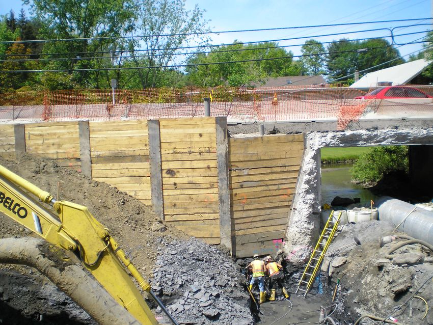
Figure 17-7 Timber Sheeting Walls
NYSDOT Geotechnical Page 17-27 January 18, 2022
Design ManualCHAPTER 17
Abutments, Retaining Walls, and Reinforced Slopes
Figure 17-8 Steel Sheeting Wall
Driving shoes are specified on the Contract Plans when hard driving or obstructions are
expected. Details for sheet pile driving shoes are provided on the Bridge Detail Sheet for
Miscellaneous Pile Details.
Details for sheeting utilized in support of staged construction are provided on the Bridge Detail
Sheet for Excavation and Embankment Sample Drawing of Stage Construction.
17.5.2.2 Soldier Pile and Lagging Walls
A soldier pile and lagging wall is a temporary or permanent non-gravity cantilevered wall which
derives lateral resistance and moment capacity through embedment of vertical wall elements
(soldier piles). The soil behind the wall is retained by lagging. The vertical elements may be
driven steel or drilled steel or cast-in-place concrete piles. Most soldier piles used on NYSDOT
projects are steel. These vertical elements are spanned by lagging which may be wood,
reinforced concrete, or precast concrete panels. Design of these walls shall be in accordance with
NYSDOT Geotechnical Design Procedure for Flexible Wall Systems, GDP-11.
NYSDOT Geotechnical Page 17-28 January 18, 2022
Design ManualCHAPTER 17
Abutments, Retaining Walls, and Reinforced Slopes
Figure 17-9 Drilled Soldier Pile and Lagging Wall
NYSDOT Geotechnical Page 17-29 January 18, 2022
Design ManualCHAPTER 17
Abutments, Retaining Walls, and Reinforced Slopes
Figure 17-10 Driven Soldier Pile and Lagging Wall
Details for soldier pile and lagging walls are provided on the Bridge Detail Sheet for Excavation
and Embankment Soldier Pile and Lagging Wall Sample Details.
17.5.2.3 Anchored/Braced Walls
Anchored/braced walls generally consist of vertical structural elements such as sheeting and
soldier piles, and lateral anchorage elements placed through or between the vertical structural
elements. Design of these walls shall be in accordance with NYSDOT Geotechnical Design
Procedure, GDP-11.
Anchor walls derive their support by two means: passive pressure on the front of the embedded
portion of the wall and anchor elements near the top of the piling. This method is suitable for
heights up to about 30 ft., depending on the soil conditions. The overall stability of anchored
sheet pile walls and the stresses in the members depends on the interaction of several factors,
such as the relative stiffness of the piling, the depth of piling penetration, the relative
compressibility and strength of the soil, the amount of achievable anchor resistance, etc.
NYSDOT Geotechnical Page 17-30 January 18, 2022
Design ManualCHAPTER 17
Abutments, Retaining Walls, and Reinforced Slopes
Figure 17-11 Anchored Temporary Soldier Pile and Lagging Wall
Figure 17-12 Anchored Permanent Soldier Pile and Lagging Wall
Details for ground anchors are provided on the Bridge Detail Sheet for Excavation and
Embankment Tieback Wall Details.
NYSDOT Geotechnical Page 17-31 January 18, 2022
Design ManualCHAPTER 17
Abutments, Retaining Walls, and Reinforced Slopes
A braced excavation is a retaining structure, usually temporary in nature, which is used to
support the sides of deep excavations. Such structures generally consist of vertical steel sheet
piling or soldier piles braced by a system of wales and struts. They are used primarily for the
excavation of trenches in construction situations where adjacent ground must be supported
against settlement or slides. Usually in urban areas, the need to prevent settlement of the adjacent
ground is a matter of prime importance, as such settlements can have detrimental effects on
the structural integrity of adjacent buildings and utilities.
Figure 17-13 Braced Temporary Soldier Pile and Lagging Wall
Details for braced excavations are provided on the Bridge Detail Sheet for Excavation and
Embankment Braced Excavation Details.
17.5.2.4 Cofferdams
Cofferdams, used to dewater excavations in bodies of water, are typically cantilevered or
braced steel sheeting. Typically sheeting is driven to a greater depth than the bottom of
excavation to prevent heaving in soft clays or piping in granular soils.
NYSDOT Geotechnical Page 17-32 January 18, 2022
Design ManualCHAPTER 17
Abutments, Retaining Walls, and Reinforced Slopes
Figure 17-14 Steel Sheeting Cofferdam
Although the design of cofferdams is typically done by the Contractor, the Geotechnical
Engineer has a responsibility to consider dewatering, as it may affect constructability of the
foundation. When the amount of dewatering is extensive (the difference between ordinary high
water and bottom-of-footing elevation is great), a depth of cut-off wall analysis should be done
(NAVFAC DM 7.1-259 to 271), to determine if it is possible (and economical) to drive sheeting
deep enough to achieve a stable excavation bottom. Checks for heaving and piping of
excavations should be performed and are shown below in Figures 17-15, 17-16, and 17-17.
For situations where this is not practically possible, a tremie seal should be specified, as
described in section 17.5.2.4.1. Note that tremie seals are typically designed and detailed on the
contract plans when the Geotechnical Engineer feels it is necessary.
Cofferdams are classified in the NYSDOT Standard Specifications as either Type 1 or Type 2.
See section 17.6.13 for a description of the types and their applications.
NYSDOT Geotechnical Page 17-33 January 18, 2022
Design ManualCHAPTER 17
Abutments, Retaining Walls, and Reinforced Slopes
Figure 17-15 Stability of Base of Braced Cut
(NAVFAC DM-7.2, 1982)
NYSDOT Geotechnical Page 17-34 January 18, 2022
Design ManualCHAPTER 17
Abutments, Retaining Walls, and Reinforced Slopes
Figure 17-16 Chart for Obtaining the Depth of Sheet Piling to
Prevent Piping in a Braced Cofferdam
(after NAVFAC DM-7.1, 1982)
NYSDOT Geotechnical Page 17-35 January 18, 2022
Design ManualCHAPTER 17
Abutments, Retaining Walls, and Reinforced Slopes
Figure 17-17 Depth of Sheet Piling in Stratified Sand to
Prevent Piping in a Braced Cofferdam
(after NAVFAC DM-7.1, 1982)
NYSDOT Geotechnical Page 17-36 January 18, 2022
Design ManualCHAPTER 17
Abutments, Retaining Walls, and Reinforced Slopes
17.5.2.4.1 Tremie Seals
If sheeting cannot be installed deep enough to cut off water and prevent piping into the
excavation, a tremie seal is an option at the bottom of excavation. The thickness of concrete is
determined based on the weight of the concrete necessary to resist the buoyant head of water
exerting upwards pressure on the bottom of excavation, as shown in Figure 17-18.
The thickness of the tremie seal (X) is calculated as follows:
C
O
E
P
H
B
T E
X S
Figure 17-18 Tremie Seal
H = head of water above B.O.F (O.H.W. - B.O.F.)
X = required tremie thickness
γw = unit weight of water = 62.4 lbs/ft3
γc = unit weight of unreinforced concrete = 140 lbs/ft3
Balance column of water [(H + X) γw] against tremie seal (Xγc)
(H+X)γw = Xγc
X = H γw /(γc - γw)
X = H(62.4/77.6)
X = H(0.80)
NYSDOT Geotechnical Page 17-37 January 18, 2022
Design ManualCHAPTER 17
Abutments, Retaining Walls, and Reinforced Slopes
When a tremie seal is needed for a pier supported on a pile foundation or spread footing on rock,
the need for an additional safety factor is unwarranted based upon the following built in factor of
safety:
• In the pile foundation cases, the uplift resistance of the piles is ignored creating a built-in
factor of safety.
• For the spread footings on rock case, the inability of the water to generate pressure
through the rock to the tremie seal is not taken into account, creating a built-in factor of
safety.
17.5.2.5 Permanent & Temporary Grouted Tieback Anchor
A Grouted Tieback is a ground anchor that consists of a pre-stressing steel element, called a
tendon (bar or strand), which is inserted below ground into a preformed hole. The tendon is
anchored to the ground by friction over the lower portion of the hole with cement grout. The
remaining tendon length is typically enclosed in a sheath which permits free movement of the
tendon. Ground anchors are typically used in cut situations requiring high retaining walls.
Other applications of ground anchors include repair of existing structures or slope stabilization.
Figure 17-19 Tieback Anchor Tendons
NYSDOT Geotechnical Page 17-38 January 18, 2022
Design ManualCHAPTER 17
Abutments, Retaining Walls, and Reinforced Slopes
Figure 17-20 Tieback Anchor and Wale with Load Test
NYSDOT Geotechnical Page 17-39 January 18, 2022
Design ManualCHAPTER 17
Abutments, Retaining Walls, and Reinforced Slopes
Figure 17-21 Multiple Row Anchored Tieback Soldier Pile & Lagging Wall
The Geotechnical Engineer shall determine that the required anchor pullout resistance can be
reasonably achieved in the rock or soil conditions. The Geotechnical Engineer shall also define
the free length for anchors in accordance with the NYSDOT LRFD Bridge Design
Specifications; NYSDOT Geotechnical Design Procedure for Flexible Wall Systems, GDP-11;
FHWA NHI-99-025, Earth Retaining Structures; and Recommendations for Prestressed Rock
and Soil Anchors by the Post-Tensioning Institute.
Grouted tiebacks are designed by the Contractor. All Grouted Tiebacks will be tested in
accordance with the NYSDOT Standard Specifications.
17.5.2.5.1 Inspection
NYSDOT Geotechnical Engineering Manual, GEM-17, Ground Anchor Inspector’s Manual
provides a quick and easy-to-use set of inspection guidelines for the various aspects of tieback
construction, including pre-installation inspection, installation, and testing. The manual provides
checklists that are intended to serve as reminders for Inspectors already familiar with tieback
installation.
NYSDOT Geotechnical Page 17-40 January 18, 2022
Design ManualYou can also read