HDR Image Analyzer - Installation and Operation Guide - HDR Monitoring Solution - AJA Video Systems
←
→
Page content transcription
If your browser does not render page correctly, please read the page content below
                    HDR Image Analyzer
                              HDR Monitoring Solution

             Installation and Operation Guide

Version 1.0r1
Published December 20, 2018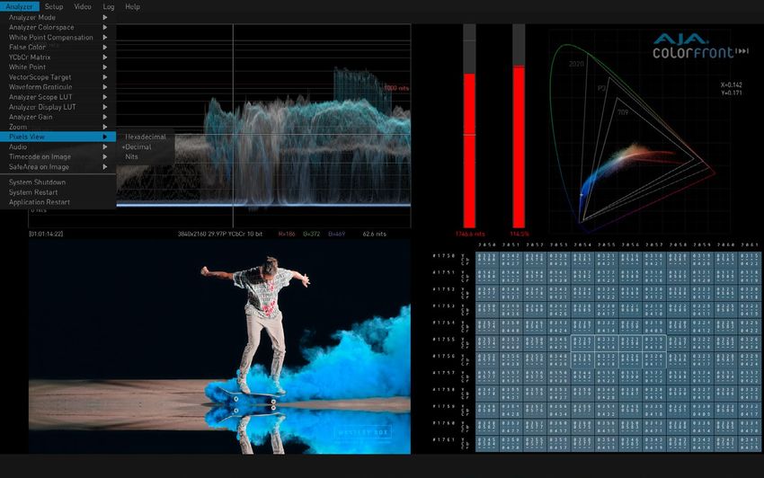
    Notices
                  Trademarks
                      AJA® and Because it matters.® are registered trademarks of AJA Video Systems, Inc.
                      for use with most AJA products. AJA™ is a trademark of AJA Video Systems, Inc. for
                      use with recorder, router, software and camera products. Because it matters.™ is a
                      trademark of AJA Video Systems, Inc. for use with camera products.
                      CION®, Corvid Ultra®, lo®, Ki Pro®, KONA®, KUMO®, ROI® and T-Tap® are registered
                      trademarks of AJA Video Systems, Inc.
                      AJA Control Room™, KiStor™, Science of the Beautiful™, TruScale™, TruZoom™,
                      V2Analog™ and V2Digital™ are trademarks of AJA Video Systems, Inc.
                      All other trademarks are the property of their respective owners.

                  Copyright
                      Copyright © 2018 AJA Video Systems, Inc. All rights reserved. All information in
                      this manual is subject to change without notice. No part of the document may be
                      reproduced or transmitted in any form, or by any means, electronic or mechanical,
                      including photocopying or recording, without the express written permission of AJA
                      Video Systems, Inc.
                      See "Colorfront Copyright Notices" on page 53 for more information.

                  Contacting AJA Support
                      When calling for support, have all information at hand prior to calling. To contact AJA
                      for sales or support, use any of the following methods:

                       Telephone           +1.530.271.3190
                       FAX                 +1.530.271.3140
                       Web                 https://www.aja.com
                       Support Email       support@aja.com
                       Sales Email         sales@aja.com

HDR Image Analyzer v1.0r1                                       2                                              www.aja.com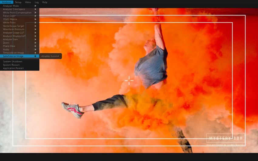
    Contents
                             Notices  .  .  .  .  .  .  .  .  .  .  .  .  .  .  .  .  .  .  .  .  .  .  .  .  .  .  .  .  .  .  .  .  .  .  .  .  .  .  2
                                    Trademarks .  .  .  .  .  .  .  .  .  .  .  .  .  .  .  .  .  .  .  .  .  .  .  .  .  .  .  .  .  .  .  .  .  .  .  .  .  .  .  .  .  .  .  2
                                    Copyright  .  .  .  .  .  .  .  .  .  .  .  .  .  .  .  .  .  .  .  .  .  .  .  .  .  .  .  .  .  .  .  .  .  .  .  .  .  .  .  .  .  .  .  .  2
                                    Contacting AJA Support .  .  .  .  .  .  .  .  .  .  .  .  .  .  .  .  .  .  .  .  .  .  .  .  .  .  .  .  .  .  .  .  .  .  .  2

                             Chapter 1 – Introduction .  .  .  .  .  .  .  .  .  .  .  .  .  .  .  .  .  .  .  .  .  .  .  .  .  .  .  5
                                    Overview .  .  .  .  .  .  .  .  .  .  .  .  .  .  .  .  .  .  .  .  .  .  .  .  .  .  .  .  .  .  .  .  .  .  .  .  .  .  .  .  .  .  .  .  . 5
                                      Software Features  .  .  .  .  .  .  .  .  .  .  .  .  .  .  .  .  .  .  .  .  .  .  .  .  .  .  .  .  .  .  .  .  .  .  .  .  .  5
                                      Hardware Features .  .  .  .  .  .  .  .  .  .  .  .  .  .  .  .  .  .  .  .  .  .  .  .  .  .  .  .  .  .  .  .  .  .  .  .  .  5

                             Chapter 2 – HDR Image Analyzer Hardware .  .  .  .  .  .  .  .  .  .  .  .  .  .  .  6
                                    Overview .  .  .  .  .  .  .  .  .  .  .  .  .  .  .  .  .  .  .  .  .  .  .  .  .  .  .  .  .  .  .  .  .  .  .  .  .  .  .  .  .  .  .  .  . 6
                                      Chassis Front  .  .  .  .  .  .  .  .  .  .  .  .  .  .  .  .  .  .  .  .  .  .  .  .  .  .  .  .  .  .  .  .  .  .  .  .  .  .  .  .  . 6
                                      Chassis Rear .  .  .  .  .  .  .  .  .  .  .  .  .  .  .  .  .  .  .  .  .  .  .  .  .  .  .  .  .  .  .  .  .  .  .  .  .  .  .  .  .  6

                             Chapter 3 – System Installation .  .  .  .  .  .  .  .  .  .  .  .  .  .  .  .  .  .  .  .  .  .  .  7
                                    Installation Summary .  .  .  .  .  .  .  .  .  .  .  .  .  .  .  .  .  .  .  .  .  .  .  .  .  .  .  .  .  .  .  .  .  .  .  .  .                 7
                                    Hardware Installation  .  .  .  .  .  .  .  .  .  .  .  .  .  .  .  .  .  .  .  .  .  .  .  .  .  .  .  .  .  .  .  .  .  .  .  .  .               7
                                       Shipping Box Contents .  .  .  .  .  .  .  .  .  .  .  .  .  .  .  .  .  .  .  .  .  .  .  .  .  .  .  .  .  .  .  .  .  .                      7
                                       Rack Mounting the Chassis .  .  .  .  .  .  .  .  .  .  .  .  .  .  .  .  .  .  .  .  .  .  .  .  .  .  .  .  .  .  .  .                        7
                                    Network Configuration  .  .  .  .  .  .  .  .  .  .  .  .  .  .  .  .  .  .  .  .  .  .  .  .  .  .  .  .  .  .  .  .  .  .  .  .                  8
                                    Initial System Startup .  .  .  .  .  .  .  .  .  .  .  .  .  .  .  .  .  .  .  .  .  .  .  .  .  .  .  .  .  .  .  .  .  .  .  .  .               8
                                    Software Update  .  .  .  .  .  .  .  .  .  .  .  .  .  .  .  .  .  .  .  .  .  .  .  .  .  .  .  .  .  .  .  .  .  .  .  .  .  .  .  .            8
                                    Licensing  .  .  .  .  .  .  .  .  .  .  .  .  .  .  .  .  .  .  .  .  .  .  .  .  .  .  .  .  .  .  .  .  .  .  .  .  .  .  .  .  .  .  .  .  .   8

                             Chapter 4 – HDR Image Analyzer GUI .  .  .  .  .  .  .  .  .  .  .  .  .  .  .  .  .  .  .  9
                                    Overview .  .  .  .  .  .  .  .  .  .  .  .  .  .  .  .  .  .  .  .  .  .  .  .  .  .  .  .  .  .  .  .  .  .  .  .  .  .  .  .  .  .  .  .  . 9
                                      Views .  .  .  .  .  .  .  .  .  .  .  .  .  .  .  .  .  .  .  .  .  .  .  .  .  .  .  .  .  .  .  .  .  .  .  .  .  .  .  .  .  .  .  .  .  . 9
                                      Drop-Down Menu Navigation .  .  .  .  .  .  .  .  .  .  .  .  .  .  .  .  .  .  .  .  .  .  .  .  .  .  .  .  .  . 9
                                      Selecting Views with the Keyboard  .  .  .  .  .  .  .  .  .  .  .  .  .  .  .  .  .  .  .  .  .  .  .  .  .  .10
                                      Analyzer Modes  .  .  .  .  .  .  .  .  .  .  .  .  .  .  .  .  .  .  .  .  .  .  .  .  .  .  .  .  .  .  .  .  .  .  .  .  .  . 11
                                    Framing Guides .  .  .  .  .  .  .  .  .  .  .  .  .  .  .  .  .  .  .  .  .  .  .  .  .  .  .  .  .  .  .  .  .  .  .  .  .  .  .  . 18
                                    Timecode on Image  .  .  .  .  .  .  .  .  .  .  .  .  .  .  .  .  .  .  .  .  .  .  .  .  .  .  .  .  .  .  .  .  .  .  .  .  . 18
                                    Lower Right Quadrant Displays .  .  .  .  .  .  .  .  .  .  .  .  .  .  .  .  .  .  .  .  .  .  .  .  .  .  .  .  .  . 19
                                      Audio Monitoring .  .  .  .  .  .  .  .  .  .  .  .  .  .  .  .  .  .  .  .  .  .  .  .  .  .  .  .  .  .  .  .  .  .  .  .  . 19
                                      Pixel Picker .  .  .  .  .  .  .  .  .  .  .  .  .  .  .  .  .  .  .  .  .  .  .  .  .  .  .  .  .  .  .  .  .  .  .  .  .  .  .  .  .  .20
                                      Log Data  .  .  .  .  .  .  .  .  .  .  .  .  .  .  .  .  .  .  .  .  .  .  .  .  .  .  .  .  .  .  .  .  .  .  .  .  .  .  .  .  .  .  .21
                                      Info Page .  .  .  .  .  .  .  .  .  .  .  .  .  .  .  .  .  .  .  .  .  .  .  .  .  .  .  .  .  .  .  .  .  .  .  .  .  .  .  .  .  .  .21
                                    Other Features .  .  .  .  .  .  .  .  .  .  .  .  .  .  .  .  .  .  .  .  .  .  .  .  .  .  .  .  .  .  .  .  .  .  .  .  .  .  .  .  .22

                             Chapter 5 – Using HDR Image Analyzer .  .  .  .  .  .  .  .  .  .  .  .  .  .  .  .  .  23
                                    HDR Image Analyzer Setups .  .  .  .  .  .  .  .  .  .  .  .  .  .  .  .  .  .  .  .  .  .  .  .  .  .  .  .  .  .  .  . 23
                                    Video Menu .  .  .  .  .  .  .  .  .  .  .  .  .  .  .  .  .  .  .  .  .  .  .  .  .  .  .  .  .  .  .  .  .  .  .  .  .  .  .  .  .  .  .24
                                       Resolution .  .  .  .  .  .  .  .  .  .  .  .  .  .  .  .  .  .  .  .  .  .  .  .  .  .  .  .  .  .  .  .  .  .  .  .  .  .  .  .  .  .24
                                       Capture .  .  .  .  .  .  .  .  .  .  .  .  .  .  .  .  .  .  .  .  .  .  .  .  .  .  .  .  .  .  .  .  .  .  .  .  .  .  .  .  .  .  .  .25
                                       Recall  .  .  .  .  .  .  .  .  .  .  .  .  .  .  .  .  .  .  .  .  .  .  .  .  .  .  .  .  .  .  .  .  .  .  .  .  .  .  .  .  .  .  .  .  .25
                                       Screenshot .  .  .  .  .  .  .  .  .  .  .  .  .  .  .  .  .  .  .  .  .  .  .  .  .  .  .  .  .  .  .  .  .  .  .  .  .  .  .  .  .  .25
                                    Analyzer Color Space and Range .  .  .  .  .  .  .  .  .  .  .  .  .  .  .  .  .  .  .  .  .  .  .  .  .  .  .  .  . 25
                                       Camera Log Analysis .  .  .  .  .  .  .  .  .  .  .  .  .  .  .  .  .  .  .  .  .  .  .  .  .  .  .  .  .  .  .  .  .  .  . 25
                                       SDR Analysis .  .  .  .  .  .  .  .  .  .  .  .  .  .  .  .  .  .  .  .  .  .  .  .  .  .  .  .  .  .  .  .  .  .  .  .  .  .  .  .  .26
                                       HLG Analysis .  .  .  .  .  .  .  .  .  .  .  .  .  .  .  .  .  .  .  .  .  .  .  .  .  .  .  .  .  .  .  .  .  .  .  .  .  .  .  .  .26
                                       HDR Analysis  .  .  .  .  .  .  .  .  .  .  .  .  .  .  .  .  .  .  .  .  .  .  .  .  .  .  .  .  .  .  .  .  .  .  .  .  .  .  .  . 26
                                    CIE xy Gamut View .  .  .  .  .  .  .  .  .  .  .  .  .  .  .  .  .  .  .  .  .  .  .  .  .  .  .  .  .  .  .  .  .  .  .  .  .  . 27
                                    YCbCr Matrix  .  .  .  .  .  .  .  .  .  .  .  .  .  .  .  .  .  .  .  .  .  .  .  .  .  .  .  .  .  .  .  .  .  .  .  .  .  .  .  .  .  .27
                                       White Point Compensation .  .  .  .  .  .  .  .  .  .  .  .  .  .  .  .  .  .  .  .  .  .  .  .  .  .  .  .  .  .  . 28
                                       False Color .  .  .  .  .  .  .  .  .  .  .  .  .  .  .  .  .  .  .  .  .  .  .  .  .  .  .  .  .  .  .  .  .  .  .  .  .  .  .  .  .  .28
                                    Pixel Picker .  .  .  .  .  .  .  .  .  .  .  .  .  .  .  .  .  .  .  .  .  .  .  .  .  .  .  .  .  .  .  .  .  .  .  .  .  .  .  .  .  .  . 29
                                    Single Line Mode .  .  .  .  .  .  .  .  .  .  .  .  .  .  .  .  .  .  .  .  .  .  .  .  .  .  .  .  .  .  .  .  .  .  .  .  .  .  . 29
                                    LUTs .  .  .  .  .  .  .  .  .  .  .  .  .  .  .  .  .  .  .  .  .  .  .  .  .  .  .  .  .  .  .  .  .  .  .  .  .  .  .  .  .  .  .  .  .  .  .  .30

HDR Image Analyzer v1.0r1                                                                         3                                                                                        www.aja.com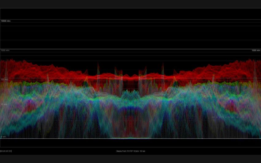
                                      Overview .  .  .  .  .  .  .  .  .  .  .  .  .  .  .  .  .  .  .  .  .  .  .  .  .  .  .  .  .  .  .  .  .  .  .  .  .  .  .  .  .  .  .30
                                    Logging  .  .  .  .  .  .  .  .  .  .  .  .  .  .  .  .  .  .  .  .  .  .  .  .  .  .  .  .  .  .  .  .  .  .  .  .  .  .  .  .  .  .  .  .  .32
                                    Settings Screen  .  .  .  .  .  .  .  .  .  .  .  .  .  .  .  .  .  .  .  .  .  .  .  .  .  .  .  .  .  .  .  .  .  .  .  .  .  .  .  . 32
                                      QC Tab .  .  .  .  .  .  .  .  .  .  .  .  .  .  .  .  .  .  .  .  .  .  .  .  .  .  .  .  .  .  .  .  .  .  .  .  .  .  .  .  .  .  .  . 32
                                      NETWORK Tab  .  .  .  .  .  .  .  .  .  .  .  .  .  .  .  .  .  .  .  .  .  .  .  .  .  .  .  .  .  .  .  .  .  .  .  .  .  .  . 33
                                      SAFE AREA Tab  .  .  .  .  .  .  .  .  .  .  .  .  .  .  .  .  .  .  .  .  .  .  .  .  .  .  .  .  .  .  .  .  .  .  .  .  .  .  .34

                             Chapter 6 – Menu Reference  .  .  .  .  .  .  .  .  .  .  .  .  .  .  .  .  .  .  .  .  .  .  .  . 36
                                    Analyzer Menu Guide  .  .  .  .  .  .  .  .  .  .  .  .  .  .  .  .  .  .  .  .  .  .  .  .  .  .  .  .  .  .  .  .  .  .  .  . 36
                                    Setup Menu Guide .  .  .  .  .  .  .  .  .  .  .  .  .  .  .  .  .  .  .  .  .  .  .  .  .  .  .  .  .  .  .  .  .  .  .  .  .  . 39
                                    Video Menu Guide .  .  .  .  .  .  .  .  .  .  .  .  .  .  .  .  .  .  .  .  .  .  .  .  .  .  .  .  .  .  .  .  .  .  .  .  .  . 39
                                    Log Menu Guide .  .  .  .  .  .  .  .  .  .  .  .  .  .  .  .  .  .  .  .  .  .  .  .  .  .  .  .  .  .  .  .  .  .  .  .  .  .  .  .40
                                    Help Menu Guide  .  .  .  .  .  .  .  .  .  .  .  .  .  .  .  .  .  .  .  .  .  .  .  .  .  .  .  .  .  .  .  .  .  .  .  .  .  .  .41
                                    Other Keyboard Shortcuts .  .  .  .  .  .  .  .  .  .  .  .  .  .  .  .  .  .  .  .  .  .  .  .  .  .  .  .  .  .  .  .  . 41

                             Appendix A – Specifications .  .  .  .  .  .  .  .  .  .  .  .  .  .  .  .  .  .  .  .  .  .  .  .  42
                                    HDR Image Analyzer Specs .  .  .  .  .  .  .  .  .  .  .  .  .  .  .  .  .  .  .  .  .  .  .  .  .  .  .  .  .  .  .  .  .42

                             Appendix B – Safety and Compliance  .  .  .  .  .  .  .  .  .  .  .  .  .  .  .  .  .  . 44
                             Colorfront Copyright Notices  .  .  .  .  .  .  .  .  .  .  .  .  .  .  .  .  .  .  .  .  .  .  .  53
                             Software License Agreement  .  .  .  .  .  .  .  .  .  .  .  .  .  .  .  .  .  .  .  .  .  .  .  54
                             Warranty and Liability Information  .  .  .  .  .  .  .  .  .  .  .  .  .  .  .  .  .  .  .  . 57
                                    Limited Warranty on Hardware .  .  .  .  .  .  .  .  .  .  .  .  .  .  .  .  .  .  .  .  .  .  .  .  .  .  .  .  .  . 57
                                    Limitation of Liability .  .  .  .  .  .  .  .  .  .  .  .  .  .  .  .  .  .  .  .  .  .  .  .  .  .  .  .  .  .  .  .  .  .  .  .  .58
                                    Governing Law and Language; Your Rights.  .  .  .  .  .  .  .  .  .  .  .  .  .  .  .  .  .  .  .  .  .  .58

                             Index .  .  .  .  .  .  .  .  .  .  .  .  .  .  .  .  .  .  .  .  .  .  .  .  .  .  .  .  .  .  .  .  .  .  .  .  .  .  . 59

HDR Image Analyzer v1.0r1                                                                       4                                                                                     www.aja.com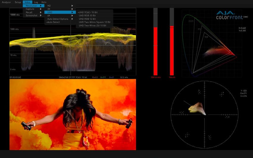
Chapter 1 – Introduction
Overview
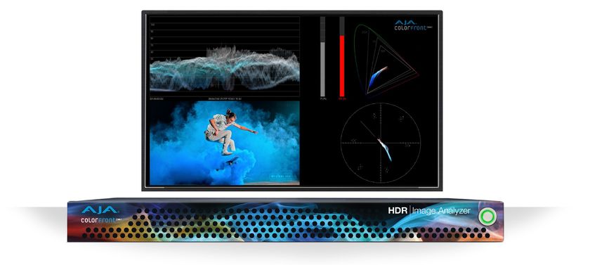
AJA's HDR Image Analyzer simplifies monitoring and analysis of 4K/UltraHD/2K/
HD, HDR and WCG content in production, post, quality control (QC) and
mastering. Tools include waveform, histogram, and vectorscope displays and Nit-
level HDR monitoring.
Combining AJA’s production-proven and powerful video and audio I/O with HDR
analysis tools from Colorfront in a compact 1RU chassis, the HDR Image Analyzer
offers a flexible solution for monitoring and analyzing HDR formats including PQ
(Perceptual Quantizer), Hybrid Log Gamma (HLG) and Rec.2020 for 4K/UltraHD
workflows. Colorfront has exclusively licensed its Colorfront Analyzer software to
AJA.
Software Features
• Precise, high quality UltraHD UI for native-resolution picture display
• Advanced out of gamut and out of brightness detection with error tolerance
• Support for SDR (Rec.709), ST2084/PQ and HLG analysis
• CIE graph, Vectorscope, Waveform
• Out of gamut false color mode to easily spot out of gamut/out of brightness
pixels
• Data analyzer with pixel picker
• Up to 4K/UltraHD 60p over 4x 3G-SDI inputs
• SDI auto signal detection
• File base error logging with timecode
• Display and color processing look up table (LUT) support
• Line mode to focus on a single horizontal line as the region of interest
• Loop through output to broadcast monitors
• Still store
• Nit levels, audio levels, and phase metering
• Built-in support for color spaces (including camera colorspaces)
Hardware Features
• One RU height chassis
• Hot swappable redundant power supplies
• Four DisplayPort outputs
• Four USB 3.0 connectors
• Two Network Interface Cards
• Three year warranty
HDR Image Analyzer v1.0r1 5 www.aja.com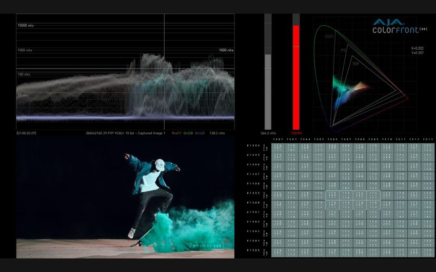
Chapter 2 – HDR Image Analyzer Hardware

Overview
                      AJA's HDR Image Analyzer is a 1RU hardware appliance equipped with AJA input
                      and output. The system is designed for immediate use, automatically powering
                      up to the Colorfront Analyzer application.

         Chassis Front
                      Figure 1. HDR Image Analyzer Chassis Front View

                                                      Cooling Airflow Entrance                                   Power Switch

                      Chassis Power Button
                      The main power switch is used to apply or remove power from the power supply
                      to the system. Turning off system power with this button removes the main
                      power but keeps standby power supplied to the system. Therefore, you must
                      unplug all system power cords before servicing.

         Chassis Rear
                      Figure 2. HDR Image Analyzer Chassis Rear View
                                                                              SDI Output        SDI Reference
                         Redundant                      Reserved              1.0/2.3 DIN      1.0/2.3 DIN BNC
                      AC Power Supplies                  for IPMI            BNCs (#5-#8)          Input (R)

                                                                                                             DisplayPort
                               Cooling Airflow Exit         USB 3.0                        SDI Input
                                                                                Unused                      Connectors (4)
                               Rear and Top Panels          Ports (4)                     1.0/2.3 DIN
                                                                        Active RJ-45     BNCs (#1-#4)
                                                      Unused            Ethernet (2)

                      Rear Panel Power Supply LEDs
                      On the rear of each power supply module an LED indicates its status as follows.
                       • Solid Green: When illuminated, indicates that the power supply is on.
                       • Solid Amber: When illuminated, indicates the power supply is plugged in and
                         turned off, or the system is off but in an abnormal state.
                       • Blinking Amber: When blinking, this system power supply temperature has
                         reached 63°C. The system will automatically power-down when the power
                         supply temperature reaches 70°C and restarts when the power supply
                         temperature goes below 60°C.

HDR Image Analyzer v1.0r1                                      6                                                     www.aja.com
Chapter 3 – System Installation

Installation Summary
                      1. Unpack the shipping box, removing the HDR Image Analyzer, two power
                         cords, and nine BNC adapter cables.
                      2. Mount the physical chassis as desired, using the provided sliding rails.
                         Cooling airflow enters the chassis from the front, and exits from the rear and
                         top panels. Do not obstruct these air vents.
                      3. Connect the two HDR Image Analyzer power cords to mains AC. For
                         redundancy, use both power supplies and connect them to separate branch
                         circuits so that the HDR Image Analyzer will continue to operate even if a
                         circuit breaker opens on one branch.
                      4. Connect a computer monitor (user supplied) to one of the rear DisplayPort
                         ports.
                      5. Connect a keyboard and mouse (user supplied) to available rear USB 3.0
                         connectors.
                      6. Connect the 1.0/2.3 DIN to full-size BNC adapter cables to the
                         HDR Image Analyzer inputs and output connectors.
                      7. Connect the HDR Image Analyzer inputs to your video source, and outputs
                         to your mastering display monitor, if used.
                      8. Power up the chassis. The system will boot up to the Analyzer application.

Hardware Installation
         Shipping Box Contents
                      An HDR Image Analyzer is shipped with two AC power cords. Rackmount brackets
                      are provided as part of the chassis.
                      As you unpack the shipping box, carefully examine the contents. Ensure you
                      received everything and that nothing was damaged during shipment. If you find
                      any damage, immediately notify the shipping service and supply them with a
                      Description of the damage. AJA will repair or replace damaged items.
                      If you find shipping damage, contact your AJA dealer or distributor for details on
                      how to have your HDR Image Analyzer repaired or replaced.
                   NOTE: Save packing materials and the shipping box. If your HDR Image Analyzer ever
                         requires service or you move your system, use the packaging materials and box
                         for safe shipment.

         Rack Mounting the Chassis
                      Install the HDR Image Analyzer chassis into a standard 19-inch wide equipment
                      rack, allowing space for cooling airflow. The chassis occupies only one vertical
                      rack unit.
                      Two rack rail assemblies are included in the rack mounting kit. Each assembly
                      consists of two sections: an inner fixed chassis rail that secures directly to the
                      server chassis and an outer fixed rack rail that secures directly to the rack itself.

HDR Image Analyzer v1.0r1                                       7                                            www.aja.com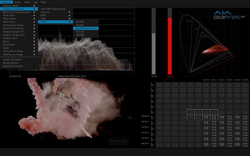
                      The rail assemblies are shipped with rack adapters installed for use with IT (square
                      hole) style rack frames. For IT racks, simply slide the unit into place, as the rails will
                      lock automatically. For use with a standard round hole rack frame, you will need
                      to remove the adapters using a small Philips head screwdriver.

Network Configuration
                      The HDR Image Analyzer ships configured for DHCP operation. If your facility
                      uses DHCP, simply connect one of the active Ethernet RJ-45 connectors to your
                      network.
                      To manually configure your HDR Image Analyzer's IP addresses, on the Analyzer
                      application press the Tab key on the keyboard when no dropdown menu is visible
                      to open the Settings screen, and select NETWORK.
                      See "NETWORK Tab" on page 33 for more information.

Initial System Startup
                      On initial system startup, no login is required, but you will need to accept EULA
                      for Microsoft and NVidia. EULA is displayed on the first startup and after every
                      update.

Software Update
                      AJA's HDR Image Analyzer ships with Colorfront's Analyzer software preinstalled
                      with the latest version.
                      Updates to the software are available at:
                             https://www.aja.com/products/support/hdr-image-analyzer
                      To update HDR Image Analyzer software:
                      1. Download the .zip file and extract and copy the .ajas file to a USB stick.
                      2. Insert the USB stick into a rear USB port on the HDR Image Analyzer chassis.
                      3. Go to Help > Update Analyzer.
                      4. Select the downloaded .ajas file and click Select File.
                      5. The software will be installed, and when complete the message
                         "Preparation Complete, please restart Analyzer" appears.
                      6. Click on the Analyzer > Application Restart menu item to complete the
                         update.

Licensing
                      The HDR Image Analyzer comes with an internal license already activated. No
                      user involvement is required for licensing.
                   NOTE: The Help > License Utility menu is for future use.

HDR Image Analyzer v1.0r1                                        8                                                www.aja.com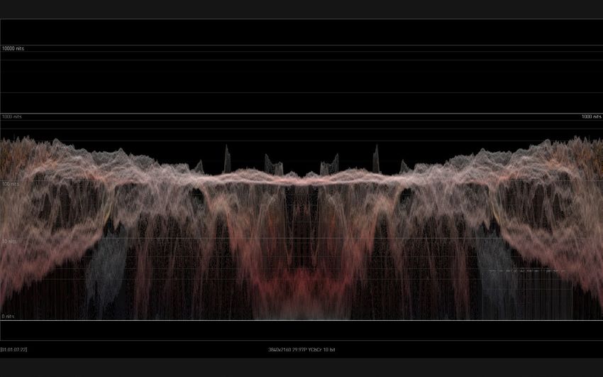
Chapter 4 – HDR Image Analyzer GUI

Overview
                      HDR Image Analyzer is a real time video analyzer for QC, Mastering, Grading
                      and Broadcast. The simple, easy to use graphical user interface features unique
                      options designed specifically for HDR work. When the HDR Image Analyzer
                      hardware starts up, the GUI automatically launches.

         Views
                      The Analyzer uses screen layouts with either a Quadrants view or Single view.
                      Figure 3. Quadrants View Example (Default)

                      Figure 4. Single View Example, Waveform RGB Color

         Drop-Down Menu Navigation
                      A top menu bar appears when the cursor is moved to the top of the screen. These
                      menus can be used to select layouts and configure settings. Clicking on a menu
                      name opens that menu.

HDR Image Analyzer v1.0r1                                    9                                         www.aja.com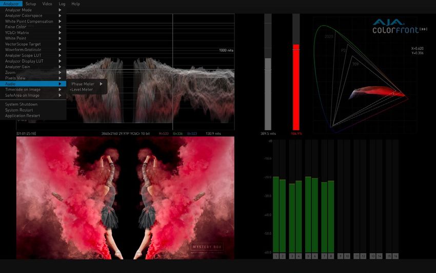
                      Pressing the ESC key also displays the Drop-Down menus.
                      Figure 5. Selecting Colorspace Using Drop-down Menu

                      When a drop-down menu is displayed:
                       • The currently selected setting is indicated with a (+) in front of that menu item.
                       • The left and right arrow keys can be used to move to an adjacent menu, or
                         open an additional parameter menu for the current menu selection.
                       • The up and down arrow keys moves the selection up or down that drop-down
                         menu.
                       • Pressing the TAB key selects the next drop-down menu to the right. Shift TAB
                         moves the drop-down menu selection to the left.
                   NOTE: When the menu bar is not displayed, the TAB key opens the Settings screen. See
                         "Settings Screen" on page 32 for more information.

         Selecting Views with the Keyboard
                      When a drop-down menu is not open, computer keyboard function keys can also
                      be used to activate the layouts.

                      Table 1. Analyzer Mode Shortcuts
                       Function Key      Activated Layout
                       F1                Show Single View video image
                       F2                Show Single View Waveform
                       F3                Show Single View Gamut
                       F4                Show Single View Vectorscope
                       F5                Show Quadrants with Audio (either Phase or Level)
                       F6                Show Quadrants with Color Picker
                       F7                Show Quadrants with Vectorscope
                       F8                Show Quadrants with Log
                       F9                Show Quadrants with Info Page

HDR Image Analyzer v1.0r1                                     10                                             www.aja.com
                      The following shortcuts, using the CTRL key, also affect the current view.

                       Shortcut          Waveform/Histogram Display
                       CTRL+F1           Select Luminance Waveform
                       CTRL+F2           Select Luminance Waveform with Colors
                       CTRL+F3           Select Color Waveform
                       CTRL+F4           Select RGB Color Waveform
                       CTRL+F5           Select RGB Waveform
                       CTRL+F6           YCbCr Waveform
                       CTRL+F7           Select YRGB Waveform
                       CTRL+F8           Select Histogram Luminance
                       CTRL+F9           Select Histogram Color
                      In addition, the following useful shortcuts are available:

                       Shortcut          Color Space Setting
                       CTRL+F10          Sets Color Space to SDR Rec 709
                       CTRL+F11          Sets Color Space to HLG Rec 2020
                       CTRL+F12          Sets Color Space to HDR Rec 2020
                       CTRL+space        Toggles Single Line Mode ON and Off
                      Keystrokes for each shortcut are listed in the drop-down menus. See "Chapter 6
                      Menu Reference" for a complete listing of all keyboard shortcuts.

         Analyzer Modes
                      The waveform, histogram, and vectorscope are a form of oscilloscope and are
                      used to monitor video brightness, contrast, hue, and color saturation.
                       • The waveform displays the luminosity or brightness and contrast of the pixels
                         in the video frame, with the top of the y-axis indicating a high luminosity level,
                         and the bottom indicating a low luminosity level.
                   NOTE: Waveform views can be magnified 4x using the Waveform Zoom control. Use the
                         mouse to move up and down the display.
                       • The histogram shows the number of pixels in relation to a given list of
                         luminance, or colors in a specific color space.
                       • The vectorscope displays values for hue and color saturation. The color
                         saturation of each pixel in the video frame is shown, with the middle of the
                         circle indicating a lower saturation level, and the edge of the circle indicating
                         a higher saturation level. Hue is represented by placement in the 360 degree
                         angle of the circle.
                   NOTE: The Vectorscope view can be displayed at either a 75% or 100% size (the
                         percentage changes the graticules on the Vectorscope, not the rasterized image),
                         and can be magnified with the Vectorscope Zoom control.
                       • The gamut screen shows a CIE xy gamut graph reporting the color values
                         present in the image, with a graticule showing the limits for various standards
                         (709, P3, 2020).
                      Several Analyzer view modes are available.

HDR Image Analyzer v1.0r1                                     11                                             www.aja.com
                      Figure 6. Waveform Luminance Mode

                      Waveform showing only luminance (Y) and no color information. Each pixel on
                      the graph shows the frequency of the corresponding luminance value in the
                      given column. Higher luminance value means lighter image content, lighter pixel
                      means higher frequency of that luminance value.
                      Figure 7. Waveform Lumi Color Mode

                      Waveform showing both luminance and color information. Here, in addition
                      to the Waveform Luminance mode, the graph is colored according to color
                      information. The hue and saturation of a pixel shows the sum of the dominant
                      colors having the corresponding luminance value.

HDR Image Analyzer v1.0r1                                  12                                          www.aja.com
                      Figure 8. Waveform Color Mode

                      Waveform showing the RGB channels superposed in one graph.
                      Figure 9. Waveform RGB Color Mode

                      Waveform showing the RGB channels in a split view, where each graph is shown
                      in its respective color.

HDR Image Analyzer v1.0r1                                 13                                        www.aja.com
                      Figure 10. Waveform RGB Mode

                      Waveform showing the RGB channels in a split view, where each graph is shown
                      in monochrome.
                      Figure 11. Waveform YCbCr Mode

                      Waveform showing luma (Y), blue minus luma (Cb), and red minus luma (Cr) in a
                      split view.

HDR Image Analyzer v1.0r1                                  14                                        www.aja.com
                      Figure 12. Waveform YRGB Mode

                      Waveform showing luminance and RGB channels in a split view, where each color
                      channel graph is shown in its respective color.
                      Figure 13. Histogram Luminance Mode

                      Histogram Luminance is showing the frequency of luminance values throughout
                      the current image content. Left-hand part is for darker, right-hand part is for
                      lighter image content.

HDR Image Analyzer v1.0r1                                   15                                         www.aja.com
                      Figure 14. Histogram Color YCbCr Mode

                      Histogram Color showing the frequency of RGB channel values throughout
                      the current image content, superposed. For each channel, the left-hand part
                      is represents image content for “0” or Black, while right-hand part represents
                      image content for "1" and White. The 0-1 range is a scale, also represented as code
                      values: (0 = 0,0,0 and 1 = 1023,1023,1023) in 10 bit code value for R, G & B.

                      Figure 15. Vectorscope Mode with markers indicating 75% values

HDR Image Analyzer v1.0r1                                    16                                            www.aja.com
                      Figure 16. Vectorscope Mode with markers indicating 100% values

                      Vectorscope is showing the hue and saturation of all pixels throughout the
                      current image content. The middle of the circle indicates a lower level of
                      saturation, while the edge of the circle indicates a higher level of saturation. The
                      brightness of the graph shows the frequency of the respective color in the image
                      content.
                   NOTE: A skin tone line is also available on the Vectorscope graticule, adjustable using
                         the Skin Tone X and Y controls in the Settings menu.

                      Figure 17. Gamut Mode (CIE xy Graph)

                      This mode displays a CIE xy Gamut, showing various output referred color gamut
                      standard limits, and also has Brightness and Gamut bars.

HDR Image Analyzer v1.0r1                                      17                                           www.aja.com
                      Brightness and Gamut Bars
                      This view also contains two bars: the brightness bar on the left indicates the
                      brightest pixel detected, the gamut bar on the right shows if the colors are within
                      the legal color gamut. The maximum values are calculated using the Tolerance
                      parameters available in the Settings Screen. The P3 color space is the limit.

Framing Guides
                      HDR Image Analyzer supports two framing guides, Safe Title and Safe Action.
                      Enabling "Safe Area on Image" displays the guides configured in the SAFEAREA
                      sub-page of the Settings screen. You can display either the Safe Title, Safe Action,
                      or both boundaries. The CTRL+s hotkey combination enables and disables the
                      framing guide display.
                      Figure 18. Framing

Timecode on Image
                      The timecode is captured from several areas including the SDI and may be
                      displayed on the image by selecting the Window › Timecode on Image menu
                      option.

HDR Image Analyzer v1.0r1                                     18                                            www.aja.com
                      Figure 19. Timecode on Display Image

Lower Right Quadrant Displays
                      The lower right quadrant of the HDR Image Analyzer GUI can display audio
                      information, a Pixel Picker, Log data, or Incoming Video Signal Info Page.
                      When in a quadrant mode, Gamut information is displayed in the upper right
                      quadrant.

         Audio Monitoring
                      The lower right quadrant of the HDR Image Analyzer GUI can display audio
                      information.

               Audio Phase Meter
                      Analyzer supports an audio phase meter which can be configured to display
                      either two channel (stereo) or eight channel (surround) audio. When configured
                      to display two channels, channels 1-2, 3-4, 5-6, or 7-8 may be displayed. When
                      configured to display 8 channels, channels 1-8, or 9-16 may be displayed.

HDR Image Analyzer v1.0r1                                   19                                        www.aja.com
                      Figure 20. Audio Phase Meter

               Audio Level Meter
                      Analyzer supports an audio level meter with up to 16 channels which can be used
                      to monitor audio levels and also display peak DB levels.
                      Figure 21. Audio Level Meter

         Pixel Picker
                      The lower right quadrant of the HDR Image Analyzer GUI can display the Pixel
                      Picker information. See "Pixel Picker" on page 29 for more information

HDR Image Analyzer v1.0r1                                   20                                         www.aja.com
                      Figure 22. Pixels Quadrant View

         Log Data
                      Selecting "Combined with Log" displays the current log data. This information can
                      be saved to log files. See "Logging" on page 32 for more in formation.
                      Figure 23. Log Data Quadrant View

         Info Page
                      Selecting "Combined with Info Page" displays useful information about the
                      current HDR Image Analyzer settings.

HDR Image Analyzer v1.0r1                                   21                                           www.aja.com
                      Figure 24. Info Page Quadrant View

Other Features
                      Other configuration options are available in the various HDR Image Analyzer
                      menus. See "Chapter 6 Menu Reference" for additional information.

HDR Image Analyzer v1.0r1                                   22                                     www.aja.com
Chapter 5 – Using HDR Image Analyzer

HDR Image Analyzer Setups
                      The top menu bar Setup menu is used to create, select, and save Setups of views
                      and parameter settings.
                      Figure 25. Setup Menu

                      Setups are always updated with the currently selected settings. If you want to
                      retain the current settings of a Setup, after the Setup has the desired settings
                      create or load a different Setup. Then any subsequent parameter changes made
                      will be applied to that new Setup. When you open the original Setup in the future
                      it will have all the desired settings.

               Create Setup
                      Opens a window to name and create a setup of the current settings.

               Open Setup
                      Displays a list of the current setups for selection.

               Delete Setup
                      When a Setup has been opened, you can delete it with this choice. The default
                      “analyzer” setup then gets loaded.

               Reset Setup
                      Resets the current Setup to factory default values.

HDR Image Analyzer v1.0r1                                      23                                        www.aja.com
Video Menu
                      The top menu bar Video drop-down menu is used to define the characteristics of
                      the video signal being analyzed, and can be used to capture and recall still video
                      images for detailed analysis.
                      Figure 26. Video Menu

         Resolution
                      Drop-down menus permit selecting HD, 2K, UltraHD, or 4K resolution and related
                      settings to manually match the incoming video being analyzed.

               Auto Detect Options
                      The Auto Detect Options setting is used to make the HDR Image Analyzer
                      automatically select the number of incoming video signals to be used, depending
                      on the detected video, or to force the use of only the first BNC input connector, or
                      force the use of all four input connectors. The auto detection is based on the VPID
                      video payload identifier (SMPTE 352M).
                      Auto Mode - HDR Image Analyzer automatically detects incoming video and uses
                        either one link, or four links as appropriate.
                      Forced 1x SDI Connection Mode - Forces use of only BNC input connector one.
                      Forced 4x SDI Connection Mode - Forces use of all four input BNC connectors.

               Auto Detect
                      The incoming video is examined and matching settings are applied. The Auto
                      Detect Options above can be used to force single or four link connection mode.
                      The auto detection is based on the VPID video payload identifier (SMPTE 352M).

               2SI LFR and HFR Input
                      For LFR (Low Frame Rate) 2SI video the Analyzer only uses SDI input 1 and 2 (four
                      wire LFR 2SI is not supported at this time).
                      For HFR (High Frame Rate) 2SI video all 4 SDI inputs are used.

HDR Image Analyzer v1.0r1                                    24                                             www.aja.com
         Capture
                      Captures the current video image. Up to four frames can be captured.
                   NOTE: Captured images are volatile, and will be lost when the HDR Image Analyzer is
                         turned off.

         Recall
                       Recalls the selected captured video image for display and detailed analysis.

         Screenshot
                      The Screenshot menu lets you capture the current Analyzer UI screen displayed on
                      the connected computer, complete with all the current analysis values. Screenshots
                      are saved as .png files to the local host computer, and can then be copied into a
                      different folder (for example an attached USB flash drive).

               Save Screenshot
                      Captures the current Analyzer UI screen. You can also use the CTRL+e hotkey.

               Copy Screenshots
                      Copy All Screenshots - Opens a file browser window allowing you to select the
                        drive and folder into which all the currently captured screenshots will be copied.
                      Copy Today's Screenshots - Copies only the screenshots captured today.
                      Copy All Except Today's Screenshots - Copies all captured screenshots except
                        those captured today.

               Delete Screenshots
                      Delete All Screenshots - Deletes all currently captured screenshots. Does not affect
                         screenshot files that have been copied into another folder.
                      Delete Today's Screenshots - Deletes only the screenshots captured today.
                      Delete All Except Today's Screenshots - Deletes all captured screenshots except
                         those captured today.

Analyzer Color Space and Range
                       You can find the analyzer range configuration options in Analyzer > Analyzer
                       Color Space menu.
                       The Analyzer supports Camera Log, and SDR and HDR (HLG and PQ) color space
                       modes. Select the appropriate option from the Analyzer > Analyzer Color Space
                       menu that matches the current image result.

         Camera Log Analysis
                       Several original camera log curves are supported for processing media in the
                       original capture color space. Supported formats are the following:
                        • ARRI LogC WideGamut
                        • CanonLog2
                        • CanonLog3
                        • Panasonic VLog/VGamut
HDR Image Analyzer v1.0r1                                    25                                             www.aja.com
                        •    Red WideGamut/Log3G10
                        •    Sony SLog3/BT2020
                        •    Sony SLog3/SGamut3
                        •    Sony SLog3/SGamut3Cine
                        •    ACEScct
                       In these modes, the waveform graticules are displayed in camera stops. To set
                       up the base level and the warning level, adjust the following settings in the QC
                       section of the Settings page (open with Tab):
                       CameraBaseGrey - Base grey level in nits; the 0 exposure line will be drawn at
                         this level.
                       CameraWhiteStopsOverGrey - Brightness warning level; it stops over base
                         level.

         SDR Analysis
                       For working with SDR gamma encoded broadcast or cinema signal, set the
                       Analyzer Range to SDR. Possible color primary options are the following:
                        • Rec.709
                        • P3 DCI
                        • P3 D65
                        • Rec.2020
                        • XYZ DCI

         HLG Analysis
                       HLG mode supports the variable Hybrid Log-Gamma color encoding. In this
                       mode, code values range from 0 to 1 and pixels do not have a specific nit level
                       interpretation. Possible color primary options are the following:
                        • Rec.709
                        • Rec.2020 (with gamut warning for colors outside of P3)

         HDR Analysis
                      HDR mode supports High Dynamic Range analysis. Peak brightness values above
                      the maximum allowed nit level are indicated red on all graphs.
                      Possible color primary options are the following:
                       • Rec.709
                       • P3 D65
                   NOTE: By default, the peak brightness threshold is set to 1000 nits according to the
                         HDR10 standard. When working with PQ masters of higher peak brightness, the
                         corresponding maximum brightness needs to be adjusted on the QC section of
                         the Settings page (open with Tab).
                       • Rec.2020 (with gamut warning for colors outside of P3)
                       • XYZ DCI
                       • XYZ D65

HDR Image Analyzer v1.0r1                                    26                                          www.aja.com
CIE xy Gamut View
                      The CIE xy Gamut View can be used to check the encoded colors on a standard
                      CIE xy graph, and to see if they are within the valid color range in case a specific
                      gamut constrain is to be enforced. This is relevant when working in the Rec.2020
                      color space, so the operator can identify that the colors are outside of the P3
                      gamut. This is a requirement for several currently popular delivery formats.
                      Figure 27. CIE xy Graph with Brightness and Gamut Bars

                      This view also contains two bars. The one on the left is the brightness bar that
                      indicates the brightest pixel detected on the actual frame. The one on the right
                      is the gamut bar that shows if the colors of the actual frame are within the legal
                      color gamut (P3 in case of Rec.2020 input color space).
                      HDR Image Analyzer uses thresholds when detecting these extremes, so using
                      the default settings a few pixels are allowed to exceed the legal limits without
                      triggering a warning.
                   NOTE: Cumulative maximum values can be displayed on the Brightness and Gamut bars
                         using the Log > Show Maximum Values parameter.

YCbCr Matrix
                      For the purpose of showing YCbCr components in various graphs (such as the
                      vectorscope or the waveform YCbCr), the result image is converted to the YUV
                      space. Select from the following formats for the specific matrix transformation:
                       • Rec.2020
                       • Rec.709

HDR Image Analyzer v1.0r1                                     27                                            www.aja.com
                      Figure 28. Signal Analysis with CIE xy Gamut Graph and Vectorscope

                   NOTE: The above settings will be reflected in the CIE xy graph and the gamut meter.

         White Point Compensation
                      White point is a marker on the CIE graph. White point compensation D65 however
                      is an option to change processing, so that if you are in XYZ Gamma2.6 colorspace
                      (Digital Cinema) you can change the Vectorscope and Waveform processing so
                      that the balanced white would be D65 instead of DCI. By default DCI white would
                      be in the center of the Vectorscope, and DCI white would have the same level in
                      the three channels of the waveform. If you turn on White Point Compensation to
                      D65, then D65 white would be in the center of the Vectorscope and D65 white
                      would have the same level in the three channels.
                        • The White Point Compensation parameter in the Analyzer menu turns
                          compensation On and Off, which will change the analysis of the incoming
                          video.
                        • The White Point parameter simply displays a box for either D65 or DCI on the
                          CIE graph, and does NOT alter the analysis of the incoming video.

         False Color
                      It is possible to use QC Player for checking illegal or near-illegal brightness and
                      gamut levels by enabling the False Color mode. The available False Color display
                      modes are the following:
                        • Brightness
                        • Brightness Warning
                        • Gamut
                        • Gamut Warning
                      In the Warning modes, pixels that are too bright or out of gamut are colored
                      red. Values at 90% of threshold are orange. The rest of the pixels are displayed in
                      grayscale.

HDR Image Analyzer v1.0r1                                     28                                           www.aja.com
Pixel Picker
                      The Pixel Picker is always active. With a left click of the mouse you can pick any
                      pixel on the image (Full Screen or Lower Left Quadrant.) Pressing F6 activates the
                      Lower Right mode, providing an extra precision view with per-pixel granularity.
                      Figure 29. Pixel Picker

               Pixel Picker Modes
                      From the menu the operator can choose how to inspect the pixel color values.
                      The options are:
                      Hexadecimal mode - Displays the hex code values of the pixels.
                      Decimal mode - Displays the decimal code values of the pixels.
                      Nit value mode - Displays the pixel brightness in Nit level.

Single Line Mode
                      Single Line Mode limits the analysis to a single horizontal line of video. This mode
                      can be used by a QC operator to verify blanking.

HDR Image Analyzer v1.0r1                                     29                                            www.aja.com
                      Figure 30. Single Line Mode

                      The line being analyzed is indicated with a contrastingly colored line, and the
                      number of the line is shown on the upper right.
                      Single Line Mode is turned on and off with the Analyzer Mode menu, or with the
                      CTRL+space hotkeys. Additionally the hotkey CTRL + Up/Down Arrow moves the
                      single line mode up and down one line at the time.

LUTs
         Overview
                      Lookup Tables (LUTs) allow the mapping of colors between color spaces.
                      The HDR Image Analyzer allows external Lookup Tables (LUTs) to be used for two
                      different purposes:
                       • A Display LUT is only applied to the image being shown and does not affect
                          the actual analysis of the pixel values. This can allow an operator to look at a
                          correct image on a display device that does not match the current video signal
                          type.
                       • A Scope LUT is applied to the video signal being processed, so all scopes,
                          waveforms etc. will be based on the remapped image.
                      No external LUTs are provided with the HDR Image Analyzer. Users can create and
                      load custom LUTs, if desired, provided they are formatted as either a *.cube or
                      *.3dmesh LUT file.
                      LUT files are loaded into and deleted using the Setup > Manage LUTs menu
                      (Figure 31 on page 31), but are not active until selected for use as either an
                      Analyzer Scope LUT or an Analyzer Display LUT (Figure 32 on page 31), using the
                      Analyzer menu selections.

HDR Image Analyzer v1.0r1                                    30                                             www.aja.com
                      Figure 31. Manage LUTs Menu

                      Figure 32. Analyzer Display LUT Menu

                      Analyzer Scope LUT
                      Generally the No LUT Analyzer Scope LUT setting should be used to maintain the
                      correct color analysis.

                      Display Scope LUT
                      Generally the Auto Analyzer Display setting should be used, which enables
                      HDR Image Analyzer to use its internal, calibrated LUTs for proper display.

HDR Image Analyzer v1.0r1                                   31                                        www.aja.com
Logging
                      Analyzer detects the events below and logs them with time stamps in a log file
                      and on screen:
                       • Gamut violations of the current colorspace.
                       • For HDR, P3 Gamut violation if HDR Colorspace is set to Rec2020.
                       • For HDR, Brightness violation. Max brightness for HDR is configured in the
                         Settings > QC tab.
                       • Time Code break
                      Figure 33. Logging with Show Maximum Values Selected.

                      A new log file can be created by starting a QC session from the Log drop-down
                      menu:
                       • Start Log to File (CTRL+l)
                       • Clear Log Data (CTRL+d)
                      You can also select the timecode or session clock to be used in the log:
                       • Log Window Timecode

Settings Screen
                      Advanced features are available on the Settings screen, allowing customization of
                      the HDR Image Analyzer GUI for special purposes. The Settings screen is accessed
                      by pressing the TAB key when the top menu line is not displayed. Click on the
                      desired tab to display the available parameters.

         QC Tab
                      These advanced settings are for experienced colorists and QC professionals,
                      permitting customization of the values used for analysis.
                      The QC parameters are saved in Setups. If you Reset a Setup, all values in QC are
                      returned to Defaults.

HDR Image Analyzer v1.0r1                                    32                                          www.aja.com
                      Figure 34. Setting Screen, QC Tab

                      The parameters are largely self explanatory, but the following special features are
                      available.

               Additional Marker for HDR
                      This control lets you add an additional custom level marker line to the Waveform
                      view. As an example, if mastering for 600 Nits Rec2020, you may want to add a
                      “600” line for visual reference.
                       • Range 1000.0 to 10,000.0
                       • Enter -1 to hide the custom level marker line

               Skin Tone
                      You can adjust the location of the skin tone line on the vectorscope display by
                      entering X and Y CIE coordinates. The default location of the skin tone line varies
                      depending on the color space being used.

               Audio Level Warning
                      Customizes the audio level warning threshold, which can vary depending on the
                      country standard.

         NETWORK Tab
                      The Network settings are used to configure the two network interface cards
                      (NICs) installed in the HDR Image Analyzer chassis.

HDR Image Analyzer v1.0r1                                     33                                           www.aja.com
                      Figure 35. Setting Screen, Network Tab

         SAFE AREA Tab
                      These settings are used to customize the Safe Area box displays, including the
                      ability to choose which (or both) regions to display.

HDR Image Analyzer v1.0r1                                   34                                        www.aja.com
                      Figure 36. Settings Screen, Safe Area Tab

                      The Safe Area parameters are saved in Setups.

HDR Image Analyzer v1.0r1                                   35       www.aja.com
Chapter 6 – Menu Reference

Analyzer Menu Guide
                      Table 2. Analyzer Menu > Analyzer Mode
                                                                                                                  Keyboard
            Sub Menu         Menu Option 1                    Description
                                                                                                                  Shortcut
            Analyzer Mode    Waveform Luminance               Select Luminance Waveform                           CTRL+F1
                             Waveform Lumi Color              Select Luminance Waveform with Colors               CTRL+F2
                             Waveform Color                   Select Color Waveform                               CTRL+F3
                             Waveform RGB Color               Select RGB Color Waveform                           CTRL+F4
                             Waveform RGB                     Select RGB Waveform                                 CTRL+F5
                             Waveform YCbCr                   Select YCbCr Waveform                               CTRL+F6
                             Waveform YRGB                    Select YRGB Waveform                                CTRL+F7
                             Histogram Luminance              Select Histogram Luminance                          CTRL+F8
                             Histogram Color                  Select Histogram Color                              CTRL+F9
                             Image                            Show Single View video image                        F1
                             Waveform                         Show Single View Waveform                           F2
                             Gamut                            Show Single View Gamut                              F3
                             Vectorscope                      Show Single View Vectorscope                        F4
                             Combined with Audio              Show Quadrants with Audio (either Phase or Level)   F5

                             Combined with Pixel Picker       Show Quadrants with Color Picker                    F6
                             Combined with Vectorscope        Show Quadrants with Vectorscope                     F7
                             Combined with Log                Show Quadrants with Log                             F8
                             Combined with Info Page          Show Quadrants with Info Page                       F9
                             Single Line Mode                 Enable Single Line Mode                             CTRL+space

HDR Image Analyzer v1.0r1                                         36                                              www.aja.com
                         Table 3. Analyzer Menu > Analyzer Colorspace, White Point Compensation,
                                False Color, YCbCr Matrix, White Point
                                                                                                                           Keyboard
           Menu              Menu Option 1    Menu Option 2          Description
                                                                                                                           Shortcut
           Analyzer          Auto HDR mode                           When On, color space is adjusted automatically
           Colorspace        change                                  according to the SDI flagging between Rec.709, HLG
                                                                     Rec.2020 and HDR Rec.
                             Camera           Arri LogC Wide         Set Arri LogC Wide Gamut colorspace
                                              Gamut
                                              Canon Log2             Set Canon Log2 colorspace
                                              Canon Log3             Set Canon Log3 colorspace
                                              Panasonic VLog/        Set Panasonic VLog/Gamut colorspace
                                              Gamut
                                              Red WideGamut/         Set Red WideGamut/Log3G10 colorspace
                                              Log3G10
                                              Sony SLog3/            Set Sony SLog3/BT2020 colorspace
                                              BT2020
                                              Sony SLog3/            Set Sony SLog3/SGamut3 colorspace
                                              SGamut3
                                              Sony SLog3/            Set Sony SLog3/SGamut3Cine colorspace
                                              SGamut3Cine
                             SDR              Rec709                 Set SDR Rec709 colorspace                             CTRL+F10
                                              P3DCI                  Set SDR P3DCI colorspace
                                              P3D65                  Set SDR P3D65 colorspace
                                              Rec2020                Set SDR Rec2020 colorspace
                                              XYZ DCI                Set SDR XYZ DCI colorspace
                             HLG              Rec709                 Set HLG Rec709 colorspace
                                              Rec2020                Set HLG Rec2020 colorspace                            CTRL+F11
                             HDR              Rec709                 Set HDR Rec709 colorspac
                                              P3D65                  Set HDR RecP3D65 colorspace
                                              Rec2020                Set HDR Rec2020 colorspace                            CTRL+F12
           White Point       Off                                     No white point compensation
           Compensation
                             D65                                     Apply D65 white point compensation to the analysis.
           False Color       Brightness                              Apply false color to entire Brightness                ALT+F1
                             Brightness                              Apply false color to Brightness above warning level   ALT+F2
                             Warning
                             Gamut                                   Apply false color to entire Gamut                     ALT+F3
                             Gamut Warning                           Apply false color to Gamut above warning level        ALT+F4
                             Off                                     No false color                                        ALT+F5
           YCbCr Matrix      Rec709                                  Image is converted to the YUV space, using Rec709.

                             Rec2020                                 Image is converted to the YUV space, using Rec2020.
           White Point       D65                                     Display a box on the CIE xy graph showing the
                                                                     position of the D65 white point. Analysis is not
                                                                     affected.
                             DCI                                     Display a box on the CIE xy graph showing the
                                                                     position of the DCI white point. Analysis is not
                                                                     affected.
                             Off                                     Hide the white point box on the CIE xy graph.

HDR Image Analyzer v1.0r1                                      37                                                         www.aja.com
                          Table 4. Analyzer Mode > Vectorscope Target, Waveform Graticule, Scope and
                                 Display LUTs, Analyzer Gain, Zoom, Pixels View
                                                                                                                          Keyboard
            Menu               Menu Option 1          Description
                                                                                                                          Shortcut
            Vectorscope        75%
            Target
                               100%
            Waveform           Default
            Graticule
                               Code Values
            Analyzer Scope     NoLUT                  No LUT applied to input signal.
            LUT
                               (selection list)       Optionally apply a variety of LUTs to the input signal being
                                                      analyzed.
            Analyzer           Display LUT            No LUT applied to display signal.
            Display LUT
                               Auto                   The LUT is automatically selected in a way that the incoming
                                                      image looks correct on a 709 SDR monitor.
                               (selection list)       Optionally apply a variety of LUTs to the displayed video image,
                                                      analysis is not affected.
            Analyzer Gain      Increase Gain          Simple increase of display gain.                                    CTRL+NumPad
                                                                                                                          Plus Sign
                               Decrease Gain          Simple decrease of display gain.                                    CTRL+NumPad
                                                                                                                          Minus Sign
                               Reset Gain             Simple reset of display gain.                                       CTRL+ENTER
            Zoom               Vectorscope Zoom       Apply a 5x magnification to the Vectorscope display.                CTRL+v
                               Waveform Zoom          Apply a 4x magnification to the Waveform display.                   CTRL+w
            Pixels View        Hexadecimal            Color picker displays hexadecimal values
                               Decimal                Color picker displays decimal values
                               Nits                   Color picker displays nits (RGB only)

                          Table 5. Analyzer Mode > Audio, Timecode, SafeArea
                                                                                                                               Keyboard
           Menu             Menu Option 1         Menu Option 2       Description
                                                                                                                               Shortcut
           Audio            Phase Meter           Channel 1-2         Show audio phase between Ch 1& 2
                                                  Channel 3-4         Show audio phase between Ch 3&4
                                                  Channel 5-6         Show audio phase between Ch 5&6
                                                  Channel 7-8         Show audio phase between Ch 7&8
                                                  Channel 1-8         Show four phase diagrams of Ch 1&2, thru Ch 7&8
                                                  Channel 9-16        Show four phase diagrams of Ch 9&10, thru Ch 15&16
                            Level Meter                               Display Level Meter
           Timecode         Enable (on/off)                           Show Timecode box on the image.                          CTRL+t
           on Image
           SafeArea on      Enable (on/off)                           Show framing guides on the image.                        CTRL+s
           Image
           System                                                     Closes the application and powers off the system.
           Shutdown
           System                                                     Restarts the system and automatically relaunches the
           Restart                                                    application.
           Application                                                Restarts the application without shutting down the
           Restart                                                    system.

HDR Image Analyzer v1.0r1                                            38                                                       www.aja.com
Setup Menu Guide
                       Table 6. Analyzer Mode > Audio, Timecode, SafeArea
                                                                                                                            Keyboard
           Menu         Menu Option 1      Description
                                                                                                                            Shortcut
           Manage       Load New LUT       Opens the Windows Explorer browser used to navigate to and load a 3d
           LUTs                            Mesh or a .cube LUT file.
                        Delete LUT         Opens a list of the currently loaded LUTs that you can select for deletion.
                        Delete All LUTs    Deletes all currently loaded LUTs.
           Create                          Opens a dialog box for naming and saving a new Setup file. This file will have
           Setup                           the current operational settings.
           Open         analyzer           Selects the "analyzer" Setup file, which is the original setup file which may
           Setup                           have been changed.
                        (selection list)   Reloads the selected Setup file.
           Delete                          Deletes the currently open Setup file.
           Setup
           Reset                           Resets the currently open Setup file to factory defaults.
           Setup

Video Menu Guide
                       Table 7. Video Menu Options
                                                                                                                      Keyboard
          Menu           Menu Option 1     Menu Option 2                      Description
                                                                                                                      Shortcut
          Resolution     HD                HD YCbCr 10Bit                     Defines an HD input video signal.
                                           HD RGB 10 Bit
                                           HD RGB 12 Bit
                                           HD RGB Dual-Link 10Bit
                                           HD RGB Dual-Link 12Bit
                         2K                2K YCbCr 10Bit                     Defines a 2K input video signal.
                                           2K RGB 10 Bit
                                           2K RGB 12 Bit
                                           2K RGB Dual-Link 10Bit
                                           2K RGB Dual-Link 12Bit
                         UHD               UHD YCbCr 10Bit                    Defines a UHD input video signal.
                                           UHD RGB 10 Bit
                                           UHD RGB 12 Bit
                                           UHD Two-Wires Square 10Bit
                                           UHD Two-Wires 2SI 10Bit
                         4K                4K YCbCr 10Bit                     Defines a 4K input video signal
                                           4K RGB 10 Bit
                                           4K RGB 12 Bit
                                           4K Two-Wires Square 10Bit
                                           4K Two-Wires 2SI 10Bit
                         AutoDetect        Auto Mode                          Automatically detects input video
                         Options                                              links
                                           Forces 1x SDI Connection           Forces single link input.
                                           Mode
                                           Forced 4x SDI Connection           Forces four link input.
                                           Mode
                         AutoDetect        Toggles Auto Detect of the
                                           incoming video resolution
                                           On or Off.

HDR Image Analyzer v1.0r1                                       39                                                         www.aja.com
                                                                                                                            Keyboard
          Menu              Menu Option 1          Menu Option 2                     Description
                                                                                                                            Shortcut
          Capture           Capture 1                                                Captures current image and stores in   ALT+NumPad 1
                                                                                     memory 1
                            Capture 2                                                Captures current image and stores in   ALT+NumPad 2
                                                                                     memory 2
                            Capture 3                                                Captures current image and stores in   ALT+NumPad 3
                                                                                     memory 3
                            Capture 4                                                Captures current image and stores in   ALT+NumPad 4
                                                                                     memory 4
          Recall            Show Live                                                Show live video signal                 CTRL+NumPad 5
                            Show Captured 1                                          Show memory 1                          CTRL+NumPad 1
                            Recall › Show                                            Show memory 2                          CTRL+NumPad 2
                            Captured 2
                            Recall › Show                                            Show memory 3                          CTRL+NumPad 3
                            Captured 3
                            Recall › Show                                            Show memory 4                          CTRL+NumPad 4
                            Captured 4
          Screenshot        Save Screenshot                                          Captures a screenshot of the           CTRL+e
                                                                                     Analyser UI to the host computer.
                            Copy Screenshot        Copy All                          Copies all captured screenshots into
                                                                                     the selected folder.
                            (Opens a file
                            browser for            Copy Today's                      Copies only screenshots captured
                            selection of a                                           today into the selected folder.
                            folder to copy to.)
                                                   Copy All Except Today's           Copies all screenshots except those
                                                                                     captured today into the selected
                                                                                     folder
                            Delete Screenshot      Delete All                        Deletes all captured screenshots
                                                                                     from the host computer.
                                                   Delete Today's                    Deletes only screenshots captured
                                                                                     today from the host computer.
                                                   Delete All Except Today's         Deletes all screenshots except
                                                                                     those captured today from the host
                                                                                     computer.

Log Menu Guide
                         Table 8. Log Menu Options
                                                                                                                               Keyboard
           Menu                Menu Option 1                  Description
                                                                                                                               Shortcut
           Start Log To File                                  Creates a new log file for a new QC session on disk              CTRL+l
           Reset Log Data                                     Clears current log data.                                         CTRL+d
           Copy Logs           Copy All Log Files
                               Copy Today's Log Files
                               Copy All Except Today's
                               Log Files
           Delete Logs         Delete All Log Files
                               Delete Today's Log Files
                               Delete All Except
                               Today's Log Files

HDR Image Analyzer v1.0r1                                               40                                                     www.aja.com
                                                                                                                           Keyboard
           Menu                Menu Option 1            Description
                                                                                                                           Shortcut
           Timestamp                                    Comments in the Log Window to be tagged based on session
                                                        clock.
           Timecode                                     Comments in the Log Window to be tagged based on SDI time
                                                        code.
           Auto                                         Shows timecode, timestamp, or both in the Log Window if the
           Timecode/                                    information is present on the incoming signal.
           Timestamp
           Timestamp -                                  Show both time stamps with session clock priority.
           Timecode
           Timecode -                                   Show both time stamps with SDI time code priority.
           Timestamp

Help Menu Guide
                         Table 9. Help Menu Options
                                                                                                                   Keyboard
          Menu                 Description
                                                                                                                   Shortcut
          About                Displays the Application name and Version information.                              ALT+Forward Slash(/)
          Update               Opens a browser allowing HDR Image Analyzer software update.
          Analyzer
          License Utility      Future use.

Other Keyboard Shortcuts
                            Keyboard Shortcut          Description
                            ALT+h                      Hide all popup windows (i.e. Help, Performance)
                            CONTROL+p                  Show/Hide Performance window
                            CTRL + Up/Down Arrow       Moves the single line mode analysis up and down one line at the time.

HDR Image Analyzer v1.0r1                                          41                                                         www.aja.com
Appendix A – Specifications
HDR Image Analyzer Specs
         Video Formats
                       • (4K) 4096 x 2160p 23.98, 24, 25, 29.97, 30, 48 A/B, 50 A/B, 59.94 A/B, 60 A/B
                       • (UltraHD) 3840 x 2160p 23.98, 24, 25, 29.97, 30, 48 A/B, 50 A/B, 59.94 A/B, 60
                         A/B
                       • (2K) 2048 x 1080p 23.98, 24, 25, 29.97, 30, 48 A/B, 50 A/B, 59.94 A/B, 60 A/B
                       • (2K) 2048 x 1080PsF 23.98, 24, 25, 29.97, 30, 48 A/B, 50 A/B, 59.94 A/B, 60 A/B
                       • (HD) 1080i 50, 59.94, 60
                       • (HD) 1080PsF 23.98, 24, 25, 29.97, 30
                       • (HD) 1080p 23.98, 24, 25, 29.97, 30, 50 A/B, 59.94 A/B, 60 A/B
                       • (HD) 720p 50, 50.94, 60

         Video Input Digital
                       • 4x 3G-SDI BNC

         Video Output Digital
                       • 4x 3G-SDI BNC

         Audio Input Digital
                       • 16-Channel 24-bit SDI embedded, 48 kHz synchronous

         Audio Output Digital
                       • 16-Channel 24-bit SDI embedded, 48 kHz synchronous

         Computer Monitor Output
                       • DisplayPort Output:
                         • Up to UltraHD 60p

         Reference Input
                       • Signal: Analog video sync (Blackburst or Tri-Level)

         Size: (w x d x h)
                       • 1RU form factor
                       • 17.2” x 16.9" x 1.7" (436.88 x 429.26 x 43.18 mm)

         Weight
                       • 28 lb (12.7kg) in box
                       • 18 lb (8.2kg) server only

         Power
                       • 100-240 VAC 50/60 Hz (Dual, redundant power supplies)
                       • 190W typical, 245W Maximum

HDR Image Analyzer v1.0r1                                     42                                          www.aja.com
         Environment
                       •     Safe Operating Temperature: 5 to 35 C (41 to 95 F)
                       •     Safe Storage Temperature (Power OFF): -40 to 60 C (-40 to 140 F)
                       •     Operating Relative Humidity: 8-90% noncondensing
                       •     Nonoperating Relative Humidity: 5-95% noncondensing

HDR Image Analyzer v1.0r1                                       43                             www.aja.com
Appendix B – Safety and Compliance
Federal Communications Commission (FCC) Compliance Notices
         Class A Interference Statement
                      This equipment has been tested and found to comply with the limits for a Class
                      A digital device, pursuant to Part 15, Subpart B of the FCC Rules. These limits
                      are designed to provide reasonable protection against harmful interference
                      in a residential installation. This equipment generates, uses, and can radiate
                      radio frequency energy and, if not installed and used in accordance with the
                      instructions, may cause harmful interference to radio communications. However,
                      there is no guarantee that interference will not occur in a particular installation. If
                      this equipment does cause harmful interference to radio or television reception,
                      which can be determined by turning the equipment off and on, the user is
                      encouraged to try to correct the interference by one or more of the following
                      measures:
                       • Reorient or relocate the receiving antenna.
                       • Increase the separation between the equipment and receiver.
                       • Connect the equipment into an outlet on a circuit different from that to which
                          the receiver is connected.
                       • Consult the dealer or an experienced radio/TV technician for help.

         FCC Caution
                      This device complies with Part 15 of the FCC Rules. Operation is subject to the
                      following two conditions: (1) This device may not cause harmful interference, and
                      (2) this device must accept any interference received, including interference that
                      may cause undesired operation.

Canadian ICES Statement
                      Canadian Department of Communications Radio Interference Regulations
                      This digital apparatus does not exceed the Class A limits for radio-noise emissions
                      from a digital apparatus as set out in the Radio Interference Regulations of
                      the Canadian Department of Communications. This Class A digital apparatus
                      complies with Canadian ICES-003.
                      Règlement sur le brouillage radioélectrique du ministère des Communications
                      Cet appareil numérique respecte les limites de bruits radioélectriques visant les
                      appareils numériques de classe A prescrites dans le Règlement sur le brouillage
                      radioélectrique du ministère des Communications du Canada. Cet appareil
                      numérique de la Classe A est conforme à la norme NMB-003 du Canada.

European Union and European Free Trade Association (EFTA)
Regulatory Compliance
                      This equipment may be operated in the countries that comprise the member
                      countries of the European Union and the European Free Trade Association. These
                      countries, listed in the following paragraph, are referred to as The European
                      Community throughout this document:
                      AUSTRIA, BELGIUM, BULGARIA, CYPRUS, CZECH REPUBLIC, DENMARK, ESTONIA,
                      FINLAND, FRANCE, GERMANY, GREECE, HUNGARY, IRELAND, ITALY, LATVIA,
                      LITHUANIA, LUXEMBOURG, MALTA, NETHERLANDS, POLAND, PORTUGAL,
                      ROMANIA, SLOVAKIA, SLOVENIA, SPAIN, SWEDEN, UNITED KINGDOM, ICELAND,
                      LICHTENSTEIN, NORWAY, SWITZERLAND

HDR Image Analyzer v1.0r1                                      44                                              www.aja.com
         Declaration of Conformity
                      Marking by this symbol indicates compliance with the Essential Requirements of
                      the EMC Directive of the European Union 2014/30/EU.

                                  This equipment meets the following conformance standards:
                      EN 60065: 2014 (T-Mark License),
                      IEC 60065: 2014 (CB Scheme Report/Certificate)
                      Additional licenses issued for specific countries available on request.
                      Emissions
                      EN 55032: 2012 + AC: 2013, CISPR 32: 2015,
                      EN 61000-3-2: 2014, EN 61000-3-3: 2013
                      Immunity
                      EN 55103-2: 2009, EN 61000-4-2:2009, EN 61000-4-3: 2006 + A1:2008 + A2:2010,
                      EN 61000-4-4: 2004 + A1:2010, EN 61000-4-5:2006, EN 61000-4-6:2009,
                      EN 61000-4-11:2004
                      Environments: E2, E3 and E4
                      The product is also licensed for additional country specific standards as required
                      for the International Marketplace.

                       Warning! This is a Class A product. In a domestic environment, this product
                         may cause radio interference, in which case, the user may be required to take
                         appropriate measures.
                       Achtung! Dieses ist ein Gerät der Funkstörgrenzwertklasse A. In Wohnbereichen
                         können bei Betrieb dieses Gerätes Rundfunkstörungen auftreten, in welchen
                         Fällen der Benutzer für entsprechende Gegenmaßnahmen verantwortlich ist.
                       Attention! Ceci est un produit de Classe A. Dans un environnement domestique,
                         ce produit risque de créer des interférences radioélectriques, il appartiendra
                         alors à l?utilisateur de prendre les mesures spécifiques appropriées..

         Recycling Notice
                       This symbol on the product or its packaging indicates that this product
                       must not be disposed of with your other household waste. Instead, it is your
                       responsibility to dispose of your waste equipment by handing it over to a
                       designated collection point for the recycling of waste electrical and electronic
                       equipment. The separate collection and recycling of your waste equipment
                       at the time of disposal will help conserve natural resources and ensure that
                       it is recycled in a manner that protects human health and the environment.
                       For more information about where you can drop off your waste for recycling,
                       please contact your local authority, or where you purchased your product.

Korea KCC Compliance Statement
               A                                                    (A )
               (                       )                                    ,
                                                                .

               Class A                           As an electromagnetic wave equipment for office use (Class A),
               (Broadcasting Communication       this equipment is intended to use in other than home area.
               Equipment for Office Use)         Sellers or users need to take note of this.

HDR Image Analyzer v1.0r1                                     45                                                 www.aja.com
Taiwan Compliance Statement

                      This is a Class A product based on the standard of the Bureau of Standards,
                      Metrology and Inspection (BSMI) CNS 13438, Class A. In a domestic environment
                      this product may cause radio interference in which case the user may be required
                      to take adequate measures.

Japan Compliance Statement

                      This is a Class A product based on the standard of the VCCI Council (VCCI 32: 2016).
                      If this equipment is used in a domestic environment, radio interference may
                      occur, in which case, the user may be required to take corrective actions.

Translated Warning and Caution Messages
                      The following caution statements, warning conventions, and warning messages
                      apply to this product and manual.

Before Operation Please Read These Instructions
                       Warning! Read and follow all warning notices and instructions marked on the
                         product or included in the documentation.
                       Avertissement! Lisez et conformez-vous à tous les avis et instructions
                         d'avertissement indiqués sur le produit ou dans la documentation.
                       Warnung! Lesen und befolgen Sie die Warnhinweise und Anweisungen, die auf
                         dem Produkt angebracht oder in der Dokumentation enthalten sind.
                       ¡Advertencia! Lea y siga todas las instrucciones y advertencias marcadas en el
                         producto o incluidas en la documentación.
                       Aviso! Leia e siga todos os avisos e instruções assinalados no produto ou incluídos
                         na documentação.
                       Avviso! Leggere e seguire tutti gli avvisi e le istruzioni presenti sul prodotto o
                         inclusi nella documentazione.

HDR Image Analyzer v1.0r1                                     46                                            www.aja.com
You can also read