HDR Image Analyzer - Installation and Operation Guide - HDR Monitoring Solution - AJA Video
←
→
Page content transcription
If your browser does not render page correctly, please read the page content below
                     HDR Image Analyzer
                              HDR Monitoring Solution

              Installation and Operation Guide

Version 2.0
Published February 10, 2020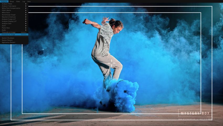
    Notices
                 Trademarks
                      AJA® and Because it matters.® are registered trademarks of AJA Video Systems, Inc.
                      for use with most AJA products. AJA™ is a trademark of AJA Video Systems, Inc. for
                      use with recorder, router, software and camera products. Because it matters.™ is a
                      trademark of AJA Video Systems, Inc. for use with camera products.
                      Corvid Ultra®, lo®, Ki Pro®, KONA®, KUMO®, ROI® and T-Tap® are registered trademarks of
                      AJA Video Systems, Inc.
                      AJA Control Room™, KiStor™, Science of the Beautiful™, TruScale™, V2Analog™ and
                      V2Digital™ are trademarks of AJA Video Systems, Inc.
                      All other trademarks are the property of their respective owners.

                 Copyright
                      Copyright © 2020 AJA Video Systems, Inc. All rights reserved. All information in
                      this manual is subject to change without notice. No part of the document may be
                      reproduced or transmitted in any form, or by any means, electronic or mechanical,
                      including photocopying or recording, without the express written permission of AJA
                      Video Systems, Inc.

                 Contacting AJA Support
                      When calling for support, have all information at hand prior to calling. To contact AJA
                      for sales or support, use any of the following methods:

                       Telephone           +1.530.271.3190
                       FAX                 +1.530.271.3140
                       Web                 https://www.aja.com
                       Support Email       support@aja.com
                       Sales Email         sales@aja.com

HDR Image Analyzer v2.0                                         2                                              www.aja.com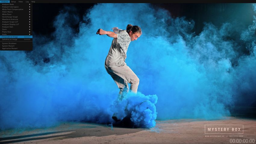
    Contents
                           Notices  .  .  .  .  .  .  .  .  .  .  .  .  .  .  .  .  .  .  .  .  .  .  .  .  .  .  .  .  .  .  .  .  .  .  .  .  .  .  2
                                  Trademarks .  .  .  .  .  .  .  .  .  .  .  .  .  .  .  .  .  .  .  .  .  .  .  .  .  .  .  .  .  .  .  .  .  .  .  .  .  .  .  .  .  .  .  2
                                  Copyright  .  .  .  .  .  .  .  .  .  .  .  .  .  .  .  .  .  .  .  .  .  .  .  .  .  .  .  .  .  .  .  .  .  .  .  .  .  .  .  .  .  .  .  .  2
                                  Contacting AJA Support .  .  .  .  .  .  .  .  .  .  .  .  .  .  .  .  .  .  .  .  .  .  .  .  .  .  .  .  .  .  .  .  .  .  .  2

                           Chapter 1 – Introduction .  .  .  .  .  .  .  .  .  .  .  .  .  .  .  .  .  .  .  .  .  .  .  .  .  .  .  5
                                  Overview .  .  .  .  .  .  .  .  .  .  .  .  .  .  .  .  .  .  .  .  .  .  .  .  .  .  .  .  .  .  .  .  .  .  .  .  .  .  .  .  .  .  .  .  . 5
                                    Software Features  .  .  .  .  .  .  .  .  .  .  .  .  .  .  .  .  .  .  .  .  .  .  .  .  .  .  .  .  .  .  .  .  .  .  .  .  .  5
                                    Hardware Features .  .  .  .  .  .  .  .  .  .  .  .  .  .  .  .  .  .  .  .  .  .  .  .  .  .  .  .  .  .  .  .  .  .  .  .  .  6

                           Chapter 2 – HDR Image Analyzer Hardware .  .  .  .  .  .  .  .  .  .  .  .  .  .  .  7
                                  Overview .  .  .  .  .  .  .  .  .  .  .  .  .  .  .  .  .  .  .  .  .  .  .  .  .  .  .  .  .  .  .  .  .  .  .  .  .  .  .  .  .  .  .  .  . 7
                                    Chassis Front  .  .  .  .  .  .  .  .  .  .  .  .  .  .  .  .  .  .  .  .  .  .  .  .  .  .  .  .  .  .  .  .  .  .  .  .  .  .  .  .  . 7
                                    Chassis Rear .  .  .  .  .  .  .  .  .  .  .  .  .  .  .  .  .  .  .  .  .  .  .  .  .  .  .  .  .  .  .  .  .  .  .  .  .  .  .  .  .  7

                           Chapter 3 – System Installation .  .  .  .  .  .  .  .  .  .  .  .  .  .  .  .  .  .  .  .  .  .  .  9
                                  Installation Summary .  .  .  .  .  .  .  .  .  .  .  .  .  .  .  .  .  .  .  .  .  .  .  .  .  .  .  .  .  .  .  .  .  .  .  .  .  9
                                  Hardware Installation  .  .  .  .  .  .  .  .  .  .  .  .  .  .  .  .  .  .  .  .  .  .  .  .  .  .  .  .  .  .  .  .  .  .  .  .  . 9
                                     Shipping Box Contents .  .  .  .  .  .  .  .  .  .  .  .  .  .  .  .  .  .  .  .  .  .  .  .  .  .  .  .  .  .  .  .  .  .  9
                                     Rack Mounting the Chassis .  .  .  .  .  .  .  .  .  .  .  .  .  .  .  .  .  .  .  .  .  .  .  .  .  .  .  .  .  .  .  . 9
                                  Network Configuration  .  .  .  .  .  .  .  .  .  .  .  .  .  .  .  .  .  .  .  .  .  .  .  .  .  .  .  .  .  .  .  .  .  .  . 10
                                  Initial System Startup .  .  .  .  .  .  .  .  .  .  .  .  .  .  .  .  .  .  .  .  .  .  .  .  .  .  .  .  .  .  .  .  .  .  .  .  .10
                                  Software Update  .  .  .  .  .  .  .  .  .  .  .  .  .  .  .  .  .  .  .  .  .  .  .  .  .  .  .  .  .  .  .  .  .  .  .  .  .  .  . 10
                                     Update with USB stick . . . . . . . . . . . . . . . . . . . . . . . . . . . . . . . . . . 10
                                     Update Using Web Browser .  .  .  .  .  .  .  .  .  .  .  .  .  .  .  .  .  .  .  .  .  .  .  .  .  .  .  .  .  .  . 11
                                  Licensing  .  .  .  .  .  .  .  .  .  .  .  .  .  .  .  .  .  .  .  .  .  .  .  .  .  .  .  .  .  .  .  .  .  .  .  .  .  .  .  .  .  .  .  . 11

                           Chapter 4 – HDR Image Analyzer GUI .  .  .  .  .  .  .  .  .  .  .  .  .  .  .  .  .  .  12
                                  Overview .  .  .  .  .  .  .  .  .  .  .  .  .  .  .  .  .  .  .  .  .  .  .  .  .  .  .  .  .  .  .  .  .  .  .  .  .  .  .  .  .  .  .  . 12
                                     Views .  .  .  .  .  .  .  .  .  .  .  .  .  .  .  .  .  .  .  .  .  .  .  .  .  .  .  .  .  .  .  .  .  .  .  .  .  .  .  .  .  .  .  .  . 12
                                     Drop-Down Menu Navigation .  .  .  .  .  .  .  .  .  .  .  .  .  .  .  .  .  .  .  .  .  .  .  .  .  .  .  .  . 14
                                     Selecting Views with Keyboard .  .  .  .  .  .  .  .  .  .  .  .  .  .  .  .  .  .  .  .  .  .  .  .  .  .  .  .  .14
                                     Analyzer Modes  .  .  .  .  .  .  .  .  .  .  .  .  .  .  .  .  .  .  .  .  .  .  .  .  .  .  .  .  .  .  .  .  .  .  .  .  .  . 15
                                  Framing Guides .  .  .  .  .  .  .  .  .  .  .  .  .  .  .  .  .  .  .  .  .  .  .  .  .  .  .  .  .  .  .  .  .  .  .  .  .  .  .  . 22
                                  Timecode on Image  .  .  .  .  .  .  .  .  .  .  .  .  .  .  .  .  .  .  .  .  .  .  .  .  .  .  .  .  .  .  .  .  .  .  .  .  . 22
                                  Audio Monitoring .  .  .  .  .  .  .  .  .  .  .  .  .  .  .  .  .  .  .  .  .  .  .  .  .  .  .  .  .  .  .  .  .  .  .  .  .  .  .23
                                     Audio Phase Meter .  .  .  .  .  .  .  .  .  .  .  .  .  .  .  .  .  .  .  .  .  .  .  .  .  .  .  .  .  .  .  .  .  .  .  .  .23
                                     Audio Level Meter .  .  .  .  .  .  .  .  .  .  .  .  .  .  .  .  .  .  .  .  .  .  .  .  .  .  .  .  .  .  .  .  .  .  .  .  .24
                                  Pixel Picker .  .  .  .  .  .  .  .  .  .  .  .  .  .  .  .  .  .  .  .  .  .  .  .  .  .  .  .  .  .  .  .  .  .  .  .  .  .  .  .  .  .  . 25
                                     Log Data  .  .  .  .  .  .  .  .  .  .  .  .  .  .  .  .  .  .  .  .  .  .  .  .  .  .  .  .  .  .  .  .  .  .  .  .  .  .  .  .  .  .  .25
                                     Info Page .  .  .  .  .  .  .  .  .  .  .  .  .  .  .  .  .  .  .  .  .  .  .  .  .  .  .  .  .  .  .  .  .  .  .  .  .  .  .  .  .  .  .26
                                  Other Features .  .  .  .  .  .  .  .  .  .  .  .  .  .  .  .  .  .  .  .  .  .  .  .  .  .  .  .  .  .  .  .  .  .  .  .  .  .  .  .  .26

                           Chapter 5 – Using HDR Image Analyzer .  .  .  .  .  .  .  .  .  .  .  .  .  .  .  .  .  27
                                  HDR Image Analyzer Setups .  .  .  .  .  .  .  .  .  .  .  .  .  .  .  .  .  .  .  .  .  .  .  .  .  .  .  .  .  .  .  . 27
                                  Video Menu .  .  .  .  .  .  .  .  .  .  .  .  .  .  .  .  .  .  .  .  .  .  .  .  .  .  .  .  .  .  .  .  .  .  .  .  .  .  .  .  .  .  .28
                                    Resolution .  .  .  .  .  .  .  .  .  .  .  .  .  .  .  .  .  .  .  .  .  .  .  .  .  .  .  .  .  .  .  .  .  .  .  .  .  .  .  .  .  .28
                                    Colorspace .  .  .  .  .  .  .  .  .  .  .  .  .  .  .  .  .  .  .  .  .  .  .  .  .  .  .  .  .  .  .  .  .  .  .  .  .  .  .  .  .  .28
                                    Transport .  .  .  .  .  .  .  .  .  .  .  .  .  .  .  .  .  .  .  .  .  .  .  .  .  .  .  .  .  .  .  .  .  .  .  .  .  .  .  .  .  .  .29
                                    Square Division .  .  .  .  .  .  .  .  .  .  .  .  .  .  .  .  .  .  .  .  .  .  .  .  .  .  .  .  .  .  .  .  .  .  .  .  .  .  .29
                                    Auto Detect Options  .  .  .  .  .  .  .  .  .  .  .  .  .  .  .  .  .  .  .  .  .  .  .  .  .  .  .  .  .  .  .  .  .  .  . 29
                                    Capture .  .  .  .  .  .  .  .  .  .  .  .  .  .  .  .  .  .  .  .  .  .  .  .  .  .  .  .  .  .  .  .  .  .  .  .  .  .  .  .  .  .  .  .29
                                    Recall  .  .  .  .  .  .  .  .  .  .  .  .  .  .  .  .  .  .  .  .  .  .  .  .  .  .  .  .  .  .  .  .  .  .  .  .  .  .  .  .  .  .  .  .  .29
                                    Screenshot .  .  .  .  .  .  .  .  .  .  .  .  .  .  .  .  .  .  .  .  .  .  .  .  .  .  .  .  .  .  .  .  .  .  .  .  .  .  .  .  .  .29
                                  Analyzer Colorspace and Range .  .  .  .  .  .  .  .  .  .  .  .  .  .  .  .  .  .  .  .  .  .  .  .  .  .  .  .  .  .30
                                    Auto HDR Mode Change .  .  .  .  .  .  .  .  .  .  .  .  .  .  .  .  .  .  .  .  .  .  .  .  .  .  .  .  .  .  .  .  .30
                                    Camera Log Analysis .  .  .  .  .  .  .  .  .  .  .  .  .  .  .  .  .  .  .  .  .  .  .  .  .  .  .  .  .  .  .  .  .  .  . 30
                                    SDR Analysis .  .  .  .  .  .  .  .  .  .  .  .  .  .  .  .  .  .  .  .  .  .  .  .  .  .  .  .  .  .  .  .  .  .  .  .  .  .  .  .  .31
                                    HLG Analysis .  .  .  .  .  .  .  .  .  .  .  .  .  .  .  .  .  .  .  .  .  .  .  .  .  .  .  .  .  .  .  .  .  .  .  .  .  .  .  .  .31

HDR Image Analyzer v2.0                                                                        3                                                                                     www.aja.com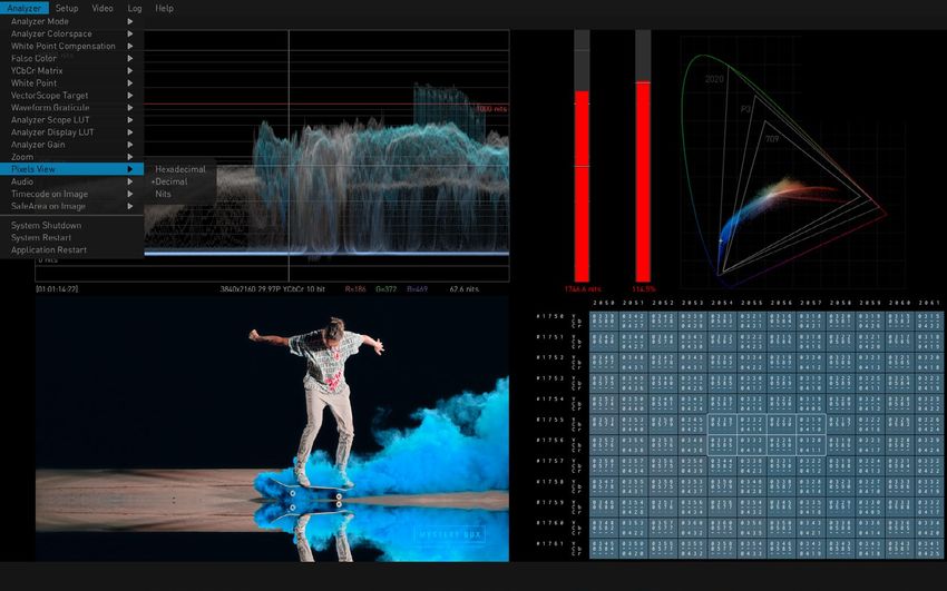
                                     HDR Analysis  .  .  .  .  .  .  .  .  .  .  .  .  .  .  .  .  .  .  .  .  .  .  .  .  .  .  .  .  .  .  .  .  .  .  .  .  .  .  .  . 31
                                  CIE xy Gamut View .  .  .  .  .  .  .  .  .  .  .  .  .  .  .  .  .  .  .  .  .  .  .  .  .  .  .  .  .  .  .  .  .  .  .  .  .  . 31
                                  YCbCr Matrix  .  .  .  .  .  .  .  .  .  .  .  .  .  .  .  .  .  .  .  .  .  .  .  .  .  .  .  .  .  .  .  .  .  .  .  .  .  .  .  .  .  .32
                                     White Point Compensation .  .  .  .  .  .  .  .  .  .  .  .  .  .  .  .  .  .  .  .  .  .  .  .  .  .  .  .  .  .  . 33
                                     False Color .  .  .  .  .  .  .  .  .  .  .  .  .  .  .  .  .  .  .  .  .  .  .  .  .  .  .  .  .  .  .  .  .  .  .  .  .  .  .  .  .  .33
                                  Pixel Picker .  .  .  .  .  .  .  .  .  .  .  .  .  .  .  .  .  .  .  .  .  .  .  .  .  .  .  .  .  .  .  .  .  .  .  .  .  .  .  .  .  .  . 34
                                  Single Line Mode .  .  .  .  .  .  .  .  .  .  .  .  .  .  .  .  .  .  .  .  .  .  .  .  .  .  .  .  .  .  .  .  .  .  .  .  .  .  . 34
                                  LUTs .  .  .  .  .  .  .  .  .  .  .  .  .  .  .  .  .  .  .  .  .  .  .  .  .  .  .  .  .  .  .  .  .  .  .  .  .  .  .  .  .  .  .  .  .  .  .  .35
                                     Overview .  .  .  .  .  .  .  .  .  .  .  .  .  .  .  .  .  .  .  .  .  .  .  .  .  .  .  .  .  .  .  .  .  .  .  .  .  .  .  .  .  .  .35
                                  Logging  .  .  .  .  .  .  .  .  .  .  .  .  .  .  .  .  .  .  .  .  .  .  .  .  .  .  .  .  .  .  .  .  .  .  .  .  .  .  .  .  .  .  .  .  .37
                                  Settings Screen  .  .  .  .  .  .  .  .  .  .  .  .  .  .  .  .  .  .  .  .  .  .  .  .  .  .  .  .  .  .  .  .  .  .  .  .  .  .  .  . 37
                                     GUI Tab .  .  .  .  .  .  .  .  .  .  .  .  .  .  .  .  .  .  .  .  .  .  .  .  .  .  .  .  .  .  .  .  .  .  .  .  .  .  .  .  .  .  .  .38
                                     QC Tab .  .  .  .  .  .  .  .  .  .  .  .  .  .  .  .  .  .  .  .  .  .  .  .  .  .  .  .  .  .  .  .  .  .  .  .  .  .  .  .  .  .  .  . 38
                                     NETWORK Tab  .  .  .  .  .  .  .  .  .  .  .  .  .  .  .  .  .  .  .  .  .  .  .  .  .  .  .  .  .  .  .  .  .  .  .  .  .  .  . 40
                                     SAFE AREA Tab  .  .  .  .  .  .  .  .  .  .  .  .  .  .  .  .  .  .  .  .  .  .  .  .  .  .  .  .  .  .  .  .  .  .  .  .  .  .  .41

                           Chapter 6 – Web Interface .  .  .  .  .  .  .  .  .  .  .  .  .  .  .  .  .  .  .  .  .  .  .  .  .  43
                                  Overview .  .  .  .  .  .  .  .  .  .  .  .  .  .  .  .  .  .  .  .  .  .  .  .  .  .  .  .  .  .  .  .  .  .  .  .  .  .  .  .  .  .  .  . 43
                                  Operation .  .  .  .  .  .  .  .  .  .  .  .  .  .  .  .  .  .  .  .  .  .  .  .  .  .  .  .  .  .  .  .  .  .  .  .  .  .  .  .  .  .  .  .43
                                  Web Interface Description  .  .  .  .  .  .  .  .  .  .  .  .  .  .  .  .  .  .  .  .  .  .  .  .  .  .  .  .  .  .  .  .  . 43
                                  Web Interface Screens .  .  .  .  .  .  .  .  .  .  .  .  .  .  .  .  .  .  .  .  .  .  .  .  .  .  .  .  .  .  .  .  .  .  .  .45
                                    Settings Screen .  .  .  .  .  .  .  .  .  .  .  .  .  .  .  .  .  .  .  .  .  .  .  .  .  .  .  .  .  .  .  .  .  .  .  .  .  .  .45
                                    Screenshots Screen  .  .  .  .  .  .  .  .  .  .  .  .  .  .  .  .  .  .  .  .  .  .  .  .  .  .  .  .  .  .  .  .  .  .  .  .46
                                    LUT Screen .  .  .  .  .  .  .  .  .  .  .  .  .  .  .  .  .  .  .  .  .  .  .  .  .  .  .  .  .  .  .  .  .  .  .  .  .  .  .  .  .  .47
                                    Logs Screen  .  .  .  .  .  .  .  .  .  .  .  .  .  .  .  .  .  .  .  .  .  .  .  .  .  .  .  .  .  .  .  .  .  .  .  .  .  .  .  .  .47
                                    Status Screen  .  .  .  .  .  .  .  .  .  .  .  .  .  .  .  .  .  .  .  .  .  .  .  .  .  .  .  .  .  .  .  .  .  .  .  .  .  .  .  .48
                                    Network Screen  .  .  .  .  .  .  .  .  .  .  .  .  .  .  .  .  .  .  .  .  .  .  .  .  .  .  .  .  .  .  .  .  .  .  .  .  .  . 48
                                    Firmware Screen .  .  .  .  .  .  .  .  .  .  .  .  .  .  .  .  .  .  .  .  .  .  .  .  .  .  .  .  .  .  .  .  .  .  .  .  .  .49

                           Chapter 7 – Menu Reference  .  .  .  .  .  .  .  .  .  .  .  .  .  .  .  .  .  .  .  .  .  .  .  . 50
                                  Analyzer Menu Guide  .  .  .  .  .  .  .  .  .  .  .  .  .  .  .  .  .  .  .  .  .  .  .  .  .  .  .  .  .  .  .  .  .  .  .  . 50
                                  Setup Menu Guide .  .  .  .  .  .  .  .  .  .  .  .  .  .  .  .  .  .  .  .  .  .  .  .  .  .  .  .  .  .  .  .  .  .  .  .  .  . 53
                                  Video Menu Guide .  .  .  .  .  .  .  .  .  .  .  .  .  .  .  .  .  .  .  .  .  .  .  .  .  .  .  .  .  .  .  .  .  .  .  .  .  . 53
                                  Log Menu Guide .  .  .  .  .  .  .  .  .  .  .  .  .  .  .  .  .  .  .  .  .  .  .  .  .  .  .  .  .  .  .  .  .  .  .  .  .  .  .  .54
                                  Help Menu Guide  .  .  .  .  .  .  .  .  .  .  .  .  .  .  .  .  .  .  .  .  .  .  .  .  .  .  .  .  .  .  .  .  .  .  .  .  .  .  .55
                                  Other Keyboard Shortcuts .  .  .  .  .  .  .  .  .  .  .  .  .  .  .  .  .  .  .  .  .  .  .  .  .  .  .  .  .  .  .  .  . 55

                           Appendix A – Specifications .  .  .  .  .  .  .  .  .  .  .  .  .  .  .  .  .  .  .  .  .  .  .  .  56
                                  HDR Image Analyzer 3G Tech Specs .  .  .  .  .  .  .  .  .  .  .  .  .  .  .  .  .  .  .  .  .  .  .  .  .  .  . 56
                                    Video Formats  .  .  .  .  .  .  .  .  .  .  .  .  .  .  .  .  .  .  .  .  .  .  .  .  .  .  .  .  .  .  .  .  .  .  .  .  .  .  . 56
                                  HDR Image Analyzer 12G Tech Specs .  .  .  .  .  .  .  .  .  .  .  .  .  .  .  .  .  .  .  .  .  .  .  .  .  .  .57

                           Appendix B – Safety and Compliance  .  .  .  .  .  .  .  .  .  .  .  .  .  .  .  .  .  . 59
                           Colorfront Copyright Notices  .  .  .  .  .  .  .  .  .  .  .  .  .  .  .  .  .  .  .  .  .  .  .  68
                           SOFTWARE LICENSE AGREEMENT  .  .  .  .  .  .  .  .  .  .  .  .  .  .  .  .  .  .  .  .  . 69
                           Warranty and Liability Information  .  .  .  .  .  .  .  .  .  .  .  .  .  .  .  .  .  .  .  . 72
                                  Limited Warranty on Hardware .  .  .  .  .  .  .  .  .  .  .  .  .  .  .  .  .  .  .  .  .  .  .  .  .  .  .  .  .  . 72
                                  Limitation of Liability .  .  .  .  .  .  .  .  .  .  .  .  .  .  .  .  .  .  .  .  .  .  .  .  .  .  .  .  .  .  .  .  .  .  .  .  .72
                                  Governing Law and Language; Your Rights  .  .  .  .  .  .  .  .  .  .  .  .  .  .  .  .  .  .  .  .  .  . 72

                           Index .  .  .  .  .  .  .  .  .  .  .  .  .  .  .  .  .  .  .  .  .  .  .  .  .  .  .  .  .  .  .  .  .  .  .  .  .  .  . 74

HDR Image Analyzer v2.0                                                                         4                                                                                        www.aja.com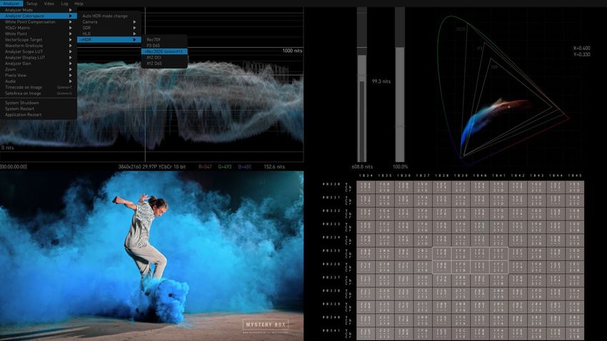
Chapter 1 – Introduction

Overview
                      AJA's HDR Image Analyzer simplifies monitoring and analysis of SDI video HDR
                      and WCG content in production, postproduction, quality control (QC) and
                      mastering. Tools include waveform, histogram, and vectorscope displays, and
                      nit-level HDR monitoring. The HDR Image Analyzer can also monitor embedded
                      audio levels and phase.
                      Combining AJA’s production-proven and powerful video and audio I/O with HDR
                      analysis tools from Colorfront in a compact 1RU chassis, the HDR Image Analyzer
                      offers a flexible solution for monitoring and analyzing HDR formats including
                      PQ (Perceptual Quantizer), Hybrid Log Gamma (HLG) and Rec2020 for up to 8K/
                      UltraHD2 workflows. Colorfront has exclusively licensed its Colorfront Analyzer
                      software to AJA.
                      Two models of AJA's HDR Image Analyzer are available:
                       • HDR Image Analyzer: HDR-IMGYZR-88 (3G-SDI model)
                       • HDR Image Analyzer 12G: HDR-IMGYZR-12G (12G-SDI model)

        Software Features
                      Both HDR Image Analyzer models have identical functionality, except as indicated
                      below:

                      Shared HDR Image Analyzer features
                       •   Precise, high quality UltraHD UI for native-resolution picture display
                       •   Advanced out-of-gamut and out-of-brightness detection with error tolerance
                       •   Support for SDR (Rec709), ST2084/PQ and HLG analysis
                       •   CIE graph, Vectorscope, Waveform
                       •   Color gamut, including out-of-gamut false color mode to easily spot out-of-
                           gamut/out-of-brightness pixels
                       •   Data analyzer with pixel picker
                       •   Up to 8K/UltraHD2 60p over 12G-SDI inputs (HDR Image Analyzer 12G only)
                       •   Up to 4K/UltraHD 60p over 4x 3G-SDI inputs
                       •   SDI auto signal detection
                       •   File base error logging with timecode
                       •   Display and color processing look up table (LUT) support
                       •   Line mode to focus on a single horizontal line as the region of interest
                       •   Loop through output to broadcast monitors
                       •   Still store
                       •   Nit levels, audio levels, and audio phase metering
                       •   Built-in support for colorspaces (including camera colorspaces)
                       •   12-bit RGB input support
                       •   PQ display over DisplayPort for compatibility with HDR displays
                       •   Desktop mirroring via DisplayPorts
                       •   Web interface for configuration and control
                       •   Remote desktop support

HDR Image Analyzer v2.0                                      5                                          www.aja.com
                      Unique HDR Image Analyzer 12G Features
                       •   12G-SDI support
                       •   8K and UltraHD2 support
                       •   Four bi-directional SDI connections, configured using software
                       •   SDI Loop through options:
                           • SDI input count: 4 -> no loop through available
                           • SDI input count: 2 -> SDI 1 loops to SDI 3, SDI 2 loops to SDI 4 for every
                             supported mode
                           • SDI input count: 1 -> SDI 1 loops to SDI 3

                      Unique HDR Image Analyzer (3G) Features
                       • Four uni-directional SDI connections, configured using software
                       • SDI Loop through options:
                         • SDI In and Out Loop through available for all supported formats and
                           transports, including quad link inputs

        Hardware Features
                      Shared HDR Image Analyzer Hardware Features
                       •   One RU height rack mountable chassis
                       •   Hot swappable redundant power supplies
                       •   Two Network Interface Cards
                       •   Four USB 3.0 connectors
                       •   Three year warranty

                      Unique HDR Image Analyzer 12G Hardware Features
                       • HD-BNC twist-lock SDI connectors, HD-BNC to BNC adapters included
                       • Three DisplayPort outputs
                       • One DisplayPort over USB-C output

                      Unique HDR Image Analyzer (3G) Hardware Features
                       • DIN 1.0/2.3 slide lock SDI connectors, DIN 1.0/2.3 to BNC adapters included
                       • Four DisplayPort outputs

HDR Image Analyzer v2.0                                         6                                        www.aja.com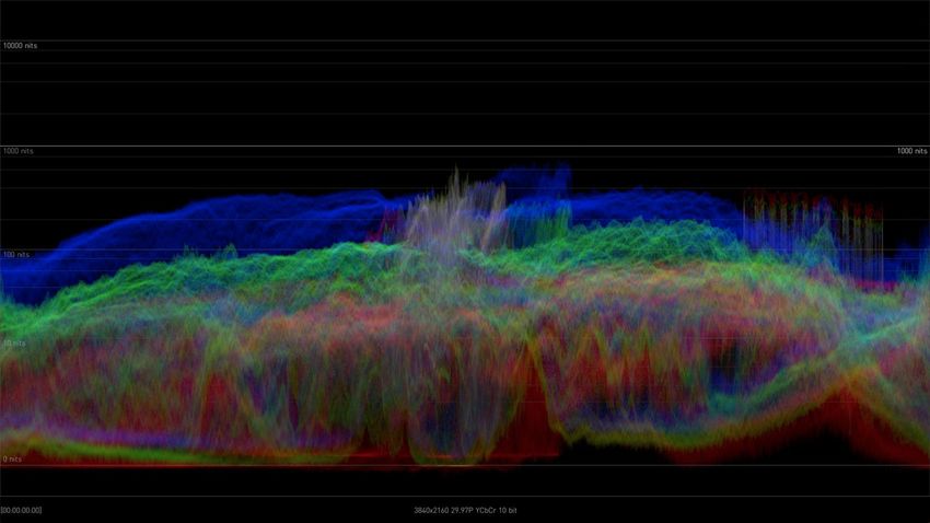
Chapter 2 – HDR Image Analyzer Hardware
Overview
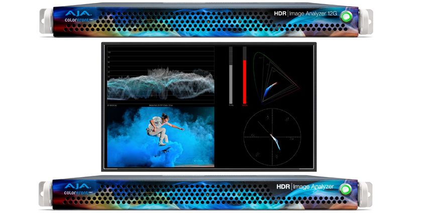
AJA's HDR Image Analyzer is a 1RU hardware appliance equipped with AJA input
and output. The system is designed for immediate use, automatically powering
up to the Colorfront Analyzer application.
Chassis Front
Figure 1. HDR Image Analyzer Chassis Front View
Cooling Airflow Entrance Power Switch
Chassis Power Button
The main power switch is used to apply or remove power from the power supply
to the system. Turning off system power with this button removes the main
power but keeps standby power supplied to the system. Therefore, you must
unplug all system power cords before servicing.
Chassis Rear
Figure 2. HDR Image Analyzer 3G Chassis Rear View
SDI Output SDI Reference
Redundant Reserved DIN 1.0/2.3 DIN 1.0/2.3
AC Power Supplies for IPMI BNCs (#5-#8) Input (R)
DisplayPort
Cooling Airflow Exit USB 3.0 SDI Input
Unused Connectors (4)
Rear and Top Panels Ports (4) DIN 1.0/2.3
Active RJ-45 BNCs (#1-#4)
Unused Ethernet (2)
HDR Image Analyzer v2.0 7 www.aja.com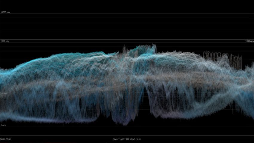
                      Figure 3. HDR Image Analyzer 12G Chassis Rear View
                                                                            Bi-directional      SDI Reference
                        Redundant                      Reserved                                   HD-BNC         DisplayPort
                                                                        HD-BNCs Supporting
                     AC Power Supplies                  for IPMI                                  Input (R)     Connectors (3)
                                                                        Up to 12G-SDI (#1-#4)

                              Cooling Airflow Exit          USB 3.0             Unused                    DisplayPort
                              Rear and Top Panels           Ports (4)                                     over USB-C
                                                                        Active RJ-45                      Connector
                                                     Unused             Ethernet (2)

                      Rear Panel Power Supply LEDs
                      On the rear of each power supply module an LED indicates its status as follows.
                       • Solid Green: When illuminated, indicates that the power supply is on.
                       • Solid Amber: When illuminated, indicates the power supply is plugged in and
                         turned off, or the system is off but in an abnormal state.
                       • Blinking Amber: When blinking, this system power supply temperature has
                         reached 63°C. The system will automatically power-down when the power
                         supply temperature reaches 70°C and restarts when the power supply
                         temperature goes below 60°C.

HDR Image Analyzer v2.0                                           8                                                    www.aja.com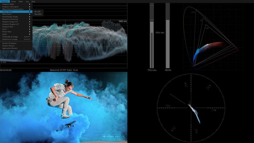
Chapter 3 – System Installation

Installation Summary
                      1. Unpack the shipping box, removing the HDR Image Analyzer, two power
                         cords, and either nine DIN 1.0/2.3 to full-size BNC adapter cables (3G model),
                         or five HD-BNC adapter cables (12G model).
                      2. Mount the physical chassis as desired, using the provided sliding rails.
                         Cooling airflow enters the chassis from the front, and exits from the rear and
                         top panels. Do not obstruct these air vents.
                      3. Connect the two HDR Image Analyzer power cords to AC mains. For
                         redundancy, use both power supplies and connect them to separate branch
                         circuits so that the HDR Image Analyzer will continue to operate even if a
                         circuit breaker opens on one branch.
                      4. Connect a computer monitor (user supplied) to one of the rear DisplayPort
                         ports.
                      5. Connect a keyboard and mouse (user supplied) to available rear USB 3.0
                         connectors.
                      6. Connect the BNC adapter cables to the HDR Image Analyzer inputs and
                         output connectors.
                   NOTE: HDR Image Analyzer 12G BNC connections are bi-directional, configured for
                         input and output via software control.
                      7. Connect the HDR Image Analyzer inputs to your video source, and outputs
                         to your mastering display monitor, if used.
                      8. Power up the chassis. The system will boot up to the Analyzer application.

Hardware Installation
        Shipping Box Contents
                      An HDR Image Analyzer is shipped with two AC power cords and BNC adapter
                      cables. Rackmount brackets are provided as part of the chassis.
                      As you unpack the shipping box, carefully examine the contents. Make sure you
                      received everything and that nothing was damaged during shipment. If you find
                      any damage, immediately notify the shipping service and supply them with a
                      description of the damage. AJA will repair or replace damaged items.
                      If you find shipping damage, contact your AJA dealer or distributor for details on
                      how to have your HDR Image Analyzer repaired or replaced.
                   NOTE: Save packing materials and the shipping box. If your HDR Image Analyzer ever
                         requires service or you move your system, use the packaging materials and box
                         for safe shipment.

        Rack Mounting the Chassis
                      Install the HDR Image Analyzer chassis into a standard 19-inch wide equipment
                      rack, allowing space for cooling airflow. The chassis occupies only one vertical
                      rack unit.

HDR Image Analyzer v2.0                                       9                                           www.aja.com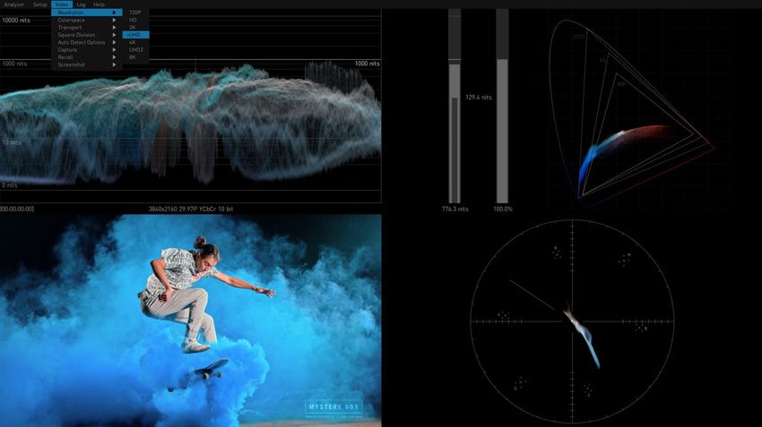
                      Two rack rail assemblies are included in the rack mounting kit. Each assembly
                      consists of two sections: an inner fixed chassis rail that secures directly to the
                      server chassis and an outer fixed rack rail that secures directly to the rack itself.
                      The rail assemblies are shipped with rack adapters installed for use with IT (square
                      hole) style rack frames. For IT racks, simply slide the unit into place, as the rails will
                      lock automatically. For use with a standard round hole rack frame, you will need
                      to remove the adapters using a small Phillips head screwdriver.

Network Configuration
                      The HDR Image Analyzer ships configured for DHCP operation. If your facility
                      uses DHCP, simply connect one of the active Ethernet RJ-45 connectors to your
                      network.
                      To manually configure your HDR Image Analyzer's IP addresses, on the Analyzer
                      application press the Tab key on the keyboard when no dropdown menu is visible
                      to open the Settings screen, and select NETWORK.
                      See "NETWORK Tab" on page 40 for more information.

Initial System Startup
                      On initial system startup, no login is required, but you will need to accept End
                      User License Agreement (EULA) for Microsoft and NVidia. EULA is displayed on
                      the first startup and after every update.

Software Update
                      AJA's HDR Image Analyzer ships with Colorfront's Analyzer software preinstalled
                      with the latest version.
                      Updates to the software are available at:
                           https://www.aja.com/products/support/hdr-image-analyzer
                           https://www.aja.com/products/hdr-image-analyzer-12g#support
                   NOTE: If you update your HDR Image Analyzer from v1.0, you will need to enter the
                         serial number of the system found on the rear of the HDR Image Analyzer chassis,
                         below the 9-pin serial port.

        Update with USB stick
                      To update HDR Image Analyzer software:
                      1. Download the .zip file and extract and copy the .ajas file to a USB stick.
                      2. Insert the USB stick into a rear USB port on the HDR Image Analyzer chassis.
                      3. Go to Help > Update Analyzer.
                      4. Select the downloaded .ajas file and click Select File.
                      5. The software will be copied to the HDR Image Analyzer, and when complete
                         the message "Preparation Complete, please restart Analyzer" appears.
                      6. Click on the Analyzer > Application Restart menu item to complete the
                         update, which can take a few minutes and might involve several system
                         restarts.

HDR Image Analyzer v2.0                                         10                                                www.aja.com
                   IMPORTANT: Do not power off the system during the software update, which can take up
                         to nine minutes.
                      7. When done, a "System shutdown is required to complete updates" message
                         appears. Click on OK to shut down the system.
                      8. Power up the HDR Image Analyzer using the front panel power button. One
                         or more end user license agreement screens will appear. Scroll down and
                         click on the Accept button for each agreement.
                      9. The HDR Image Analyzer application will then launch, ready for operation.

        Update Using Web Browser
                      Since v1.1, HDR Image Analyzer supports software update using a Web Browser
                      running on a separate network connected computer.
                      1. Download the .zip file and extract the .ajas file to a location on a network
                         connected computer.
                      2. Open a web browser on that computer and enter the IP address of your
                         HDR Image Analyzer. A webpage will be displayed.
                      3. Go to the Firmware menu and click on Choose a file...
                      4. Navigate to the saved location on the computer, select the .ajas file from the
                         list on the HDR Image Analyzer's host computer, and click Submit.
                      5. The software will be installed, which can take a few minutes and might
                         involve several system restarts.
                   IMPORTANT: Do not power off the system during the software update.
                      6. When done, a "System shutdown is required to complete updates" message
                         appears. Go to the HDR Image Analyzer's computer and click OK to shut
                         down the system.
                      7. Power up the HDR Image Analyzer using the front panel power button. One
                         or more end user agreement screens will appear. Scroll down and click on
                         the Accept button for each agreement.
                      8. The HDR Image Analyzer application will then launch, ready for operation.

Licensing
                      The HDR Image Analyzer comes with an internal license already activated. No user
                      involvement is required for licensing, other than accepting end user agreements.

HDR Image Analyzer v2.0                                       11                                         www.aja.com
Chapter 4 – HDR Image Analyzer GUI

Overview
                      HDR Image Analyzer is a real time video analyzer for QC, Mastering, Grading
                      and Broadcast. The simple, easy to use graphical user interface features unique
                      options designed specifically for HDR work. When the HDR Image Analyzer
                      hardware starts up, the GUI automatically launches.
                      HDR Image Analyzer interface provides a quadrant layout for viewing your tools
                      and footage as you work. Quick key shortcuts provide pre-configured common
                      layouts for how your tools and views are presented. For further customization,
                      you can also choose a particular tool to be shown in any of the quadrants by
                      either right-clicking on the quadrant itself and choosing your preferred tool, or by
                      accessing quadrant choices from the Analyzer Mode menu

        Views
                      The Analyzer uses screen layouts with either a Quadrants view or Single view.
                      Figure 4. Quadrants View Example

                      Each screen quadrant can be configured to display the image being examined, or
                      any of the available measurement tools.
                      Figure 5. Quadrants View Example, Alternate Configuration

HDR Image Analyzer v2.0                                       12                                            www.aja.com
                      The tool or image in each quadrant can be selected by right-clicking on that
                      quadrant to open a drop-down selection menu for that quadrant (Figure 6).
                      Figure 6. Quadrants View Example, Right-click Configuration

                      Quadrants can also be configured using the top menu bar's Analyzer Mode drop-
                      down (Figure 7).
                      Figure 7. Quadrants View Example, Analyzer Mode Drop-Down Configuration

                      In Single View, the image being examined, or some of the selected measurement
                      tools, can be displayed full screen.
                      Figure 8. Single View Example, Waveform RGB Color

HDR Image Analyzer v2.0                                     13                                       www.aja.com
        Drop-Down Menu Navigation
                      A top menu bar appears when the cursor is moved to the top of the screen. These
                      menus can be used to select layouts and configure settings. Clicking on a menu
                      name opens that menu.
                      Pressing the ESC key also displays the drop-down menus.
                      Figure 9. Selecting Colorspace Using Drop-Down Menu

                      When a drop-down menu is displayed:
                       • The currently selected setting is indicated with a (+) in front of that menu item.
                       • The left and right arrow keys can be used to move to an adjacent menu, or
                         open an additional parameter menu for the current menu selection.
                       • The up and down arrow keys moves the selection up or down that drop-down
                         menu.
                       • Pressing the TAB key selects the next drop-down menu to the right. Shift+TAB
                         moves the drop-down menu selection to the left.
                   NOTE: When the menu bar is not displayed, the TAB key opens the Settings screen. See
                         "Settings Screen" on page 37 for more information.

        Selecting Views with Keyboard
                      When a drop-down menu is not open, computer keyboard function keys can also
                      be used to activate the layouts.

HDR Image Analyzer v2.0                                       14                                             www.aja.com
                      Table 1. Analyzer Mode Shortcuts
                       Function Key      Activated Layout
                       F1                Show Single View video Image. Press again to return to
                                         Quadrants view.
                       F2                Show Single View Waveform. Press again to return to
                                         Quadrants view.
                       F3                Show Single View Gamut. Press again to return to Quadrants
                                         view.
                       F4                Show Single View Vectorscope. Press again to return to
                                         Quadrants view.
                       F5                Cycles only Q1 through Image, Waveform, Gamut,
                                         Vectorscope, and Audio views.
                       F6                Cycles only Q2 through the five views above
                       F7                Cycles only Q3 through the five views above
                       F8                Cycles only Q4 through the five views above
                      The following shortcuts, using the CTRL key, also affect the current view.

                       Shortcut          Waveform/Histogram Display
                       CTRL+F5           Cycles Q1 tool variant. The Image display cycles through
                                         Brightness and Gamut tools, and the Waveform display cycles
                                         through Luminance and Color tools.
                       CTRL+F6           Cycles Q2 tool variant as above.
                       CTRL+F7           Cycles Q3 tool variant as above.
                       CTRL+F8           Cycles Q4 tool variant as above.
                      In addition, the following useful shortcuts are available:

                       Shortcut          Colorspace Setting
                       CTRL+F10          Sets Colorspace to SDR Rec 709
                       CTRL+F11          Sets Colorspace to HLG Rec 2020
                       CTRL+F12          Sets Colorspace to HDR Rec 2020
                       CTRL+space        Toggles Single Line Mode ON and Off
                      Keystrokes for each shortcut are listed in the drop-down menus. See "Chapter 7
                      Menu Reference" for a complete listing of all keyboard shortcuts.

        Analyzer Modes
                      The waveform, histogram, and vectorscope are a form of oscilloscope and are
                      used to monitor video brightness, contrast, hue, and color saturation.
                       • The waveform displays the luminosity or brightness and contrast of the pixels
                         in the video frame, with the top of the y-axis indicating a high luminosity level,
                         and the bottom indicating a low luminosity level.
                   NOTE: Waveform views can be magnified 4x using the Waveform Zoom control. Use the
                         mouse to move up and down the display.
                       • The histogram shows the number of pixels in relation to a given list of
                         luminance, or colors in a specific colorspace.
                       • The vectorscope displays values for hue and color saturation. The color
                         saturation of each pixel in the video frame is shown, with the middle of the
                         circle indicating a lower saturation level, and the edge of the circle indicating
                         a higher saturation level. Hue is represented by placement in the 360 degree
                         angle of the circle.

HDR Image Analyzer v2.0                                       15                                             www.aja.com
                   NOTE: The Vectorscope view can be displayed at either a 75% or 100% size (the
                         percentage changes the graticules on the Vectorscope, not the rasterized image),
                         and can be magnified with the Vectorscope Zoom control.
                       • The gamut screen shows a CIE xy gamut graph reporting the color values
                         present in the image, with a graticule showing the limits for various standards
                         (709, P3, 2020).
                      Several Analyzer view modes are available.
                      Figure 10. Waveform Luminance Mode

                      Waveform showing only luminance (Y) and no color information. Each pixel on
                      the graph shows the frequency of the corresponding luminance value in the
                      given column. Higher luminance value means lighter image content, lighter pixel
                      means higher frequency of that luminance value.
                      Figure 11. Waveform Lumi Color Mode

HDR Image Analyzer v2.0                                       16                                           www.aja.com
                      Waveform showing both luminance and color information. Here, in addition
                      to the Waveform Luminance mode, the graph is colored according to color
                      information. The hue and saturation of a pixel shows the sum of the dominant
                      colors having the corresponding luminance value.
                      Figure 12. Waveform Color Mode

                      Waveform showing the RGB channels superposed in one graph.
                      Figure 13. Waveform RGB Color Mode

                      Waveform showing the RGB channels in a split view, where each graph is shown
                      in its respective color.

HDR Image Analyzer v2.0                                    17                                       www.aja.com
                      Figure 14. Waveform RGB Mode

                      Waveform showing the RGB channels in a split view, where each graph is shown
                      in monochrome.
                      Figure 15. Waveform YCbCr Mode

                      Waveform showing luma (Y), blue minus luma (Cb), and red minus luma (Cr) in a
                      split view.

HDR Image Analyzer v2.0                                    18                                        www.aja.com
                      Figure 16. Waveform YRGB Mode

                      Waveform showing luminance and RGB channels in a split view, where each color
                      channel graph is shown in its respective color.
                      Figure 17. Histogram Luminance Mode

                      Histogram Luminance is showing the frequency of luminance values throughout
                      the current image content. Left-hand part is for darker, right-hand part is for
                      lighter image content.

HDR Image Analyzer v2.0                                     19                                         www.aja.com
                      Figure 18. Histogram Color YCbCr Mode

                      Histogram Color showing the frequency of RGB channel values throughout
                      the current image content, superposed. For each channel, the left-hand part
                      represents image content for “0” or Black, while right-hand part represents image
                      content for "1" and White. The 0-1 range is a scale, also represented as code
                      values: (0 = 0,0,0 and 1 = 1023,1023,1023) in 10 bit code value for R, G & B.

                      Figure 19. Gamut Mode (CIE xy Graph) with Gamut Error

                      This mode displays a CIE xy Gamut, showing various output referred color gamut
                      standard limits, and also has Brightness and Gamut bars.

                      Brightness and Gamut Bars
                      This view also contains two bars: the brightness bar on the left indicates the
                      brightest pixel detected, the gamut bar on the right shows if the colors are within
                      the legal color gamut. See "CIE xy Gamut View" on page 31 for more information.

HDR Image Analyzer v2.0                                      20                                            www.aja.com
                      Figure 20. Vectorscope with markers indicating 75% values

                      Vectorscope is showing the hue and saturation of all pixels throughout the
                      current image content. The middle of the circle indicates a lower level of
                      saturation, while the edge of the circle indicates a higher level of saturation. The
                      brightness of the graph shows the frequency of the respective color in the image
                      content.
                      Figure 21. Vectorscope with markers indicating 100% values, Vectorscope Aid

               Skin Tone Line
                      A skin tone line is also available on the Vectorscope graticule, adjustable using
                      the Skin Tone X and Y controls in the Settings menu.

HDR Image Analyzer v2.0                                       21                                            www.aja.com
               Vectorscope Aid
                      A Vectorscope Aid feature is available in the Settings menu, which draws a grey
                      bounding area around the chroma on the Vectorscope, which can be useful when
                      trying to examine individual pixels.

Framing Guides
                      HDR Image Analyzer supports two framing guides, Safe Title and Safe Action.
                      Enabling "Safe Area on Image" displays the guides configured in the SAFEAREA
                      sub-page of the Settings screen. You can display either the Safe Title, Safe Action,
                      or both boundaries. The CTRL+s hotkey combination enables and disables the
                      framing guide display.
                      Figure 22. Framing Guides

Timecode on Image
                      The timecode is captured from several areas including the SDI and may be
                      displayed on the image by selecting the Window › Timecode on Image menu
                      option.

HDR Image Analyzer v2.0                                       22                                            www.aja.com
                      Figure 23. Timecode on Display Image (Lower Right Corner)

Audio Monitoring
                      Any quadrant of the HDR Image Analyzer GUI can display one of the audio
                      monitoring screens. In the following examples the various tools are shown in the
                      lower right quadrant (Q4).

        Audio Phase Meter
                      Analyzer supports an audio phase meter which can be configured to display
                      either two channel (stereo) or eight channel (surround) audio. When configured
                      to display two channels, channels 1-2, 3-4, 5-6, or 7-8 may be displayed. When
                      configured to display 8 channels, channels 1-8, or 9-16 may be displayed.

HDR Image Analyzer v2.0                                     23                                          www.aja.com
                      Figure 24. Audio Phase Meter

        Audio Level Meter
                      Analyzer supports an audio level meter with up to 16 channels which can be used
                      to monitor audio levels and also display peak dB levels.
                      Figure 25. Audio Level Meter

HDR Image Analyzer v2.0                                    24                                          www.aja.com
Pixel Picker
                      The HDR Image Analyzer GUI can display Pixel Picker information. See "Pixel
                      Picker" on page 34 for more information.
                      Figure 26. Pixel Picker Quadrant View

        Log Data
                      When Log is selected for a quadrant, the current log data is displayed. This
                      information can be saved to log files. See "Logging" on page 37 for more
                      information.
                      Figure 27. Log Data Quadrant View

HDR Image Analyzer v2.0                                      25                                     www.aja.com
        Info Page
                      When Info is selected for a quadrant, useful information about the current
                      HDR Image Analyzer settings is displayed.
                      Figure 28. Info Page Quadrant View

Other Features
                      Other configuration options are available in the various HDR Image Analyzer
                      menus. See "Chapter 7 Menu Reference" for additional information.

HDR Image Analyzer v2.0                                     26                                     www.aja.com
Chapter 5 – Using HDR Image Analyzer

HDR Image Analyzer Setups
                      The Setup menu of the top menu bar is used to create, select, and save Setups of
                      views and parameter settings.
                      Figure 29. Setup Menu

                      An opened Setup is updated with any changes made to the HDR Image Analyzer's
                      current settings. This ensures whenever a Setup is loaded, the last configuration
                      that was used for that Setup will be restored.
                      If you want to save a "snapshot" of the current settings, after opening or creating
                      a Setup and creating the configuration you wish to save, simply create or load a
                      new Setup. Any subsequent parameter changes will be made to the new Setup,
                      and the "snapshot" of settings for that earlier Setup will be recalled later when
                      that earlier Setup is opened.

               Create Setup
                      Opens a window to name and create a setup of the current settings.

               Open Setup
                      Displays a list of the current setups for selection.

               Delete Setup
                      When a Setup has been opened, you can delete it with this choice. The default
                      “analyzer” setup then gets loaded.

HDR Image Analyzer v2.0                                        27                                          www.aja.com
               Reset Setup
                      Resets the current Setup to factory default values.

Video Menu
                      The Video drop-down menu of the top menu bar is used to define the
                      characteristics of the video signal being analyzed, and can be used to capture and
                      recall still video images for detailed analysis.
                      Figure 30. Video Menu

                   NOTE: If Auto Detect is On, the HDR Image Analyzer will automatically select (if possible)
                         the incoming video's Resolution, Colorspace, Transport, and Square Division
                         settings.

        Resolution
                      A drop-down menu permits selecting a resolution to manually match the
                      incoming video being analyzed. Select from:
                       • 720p
                       • HD
                       • 2K
                       • UHD
                       • 4K
                       • UHD2 (12G model only)
                       • 8K (12G model only)

        Colorspace
                      A drop-down menu permits selecting from YCbCr 10 bit, RGB 10 bit, or RGB 12 bit
                      colorspaces to manually match the incoming video being analyzed. Select from:
                       • YCbCr 10 bit
                       • RGB 10 bit
                       • RGB 12 bit

HDR Image Analyzer v2.0                                        28                                              www.aja.com
        Transport
                      A drop-down menu permits selecting the SDI transport to manually match the
                      incoming video being analyzed. Select from:
                       • Single Link
                       • Dual Link
                       • Quad Link

        Square Division
                      A drop-down menu permits selecting the pixel mapping of incoming video.
                      Select from:
                       • SQD - Square Division
                       • 2SI - Two Sample Interleave

               2SI LFR and HFR Input
                      For LFR (Low Frame Rate) 2SI video the Analyzer only uses SDI input 1 and 2 (four
                      wire LFR 2SI is not supported at this time).
                      For HFR (High Frame Rate) 2SI video all 4 SDI inputs are used.

        Auto Detect Options
                      The Auto Detect Options setting is used to make the HDR Image Analyzer
                      automatically select the number of incoming video signals to be used depending
                      on the detected video, or to force the use of only the first BNC input connector, or
                      to force the use of all four input connectors. The auto detection is based on the
                      VPID video payload identifier (SMPTE 352M).
                      Auto Detect - HDR Image Analyzer automatically detects incoming video and
                        uses either one link, or four links as appropriate.
                      Forced 1x SDI Connection Mode - Forces use of only BNC input connector one.
                      Forced 4x SDI Connection Mode - Forces use of all four input BNC connectors.
                      Allow Loop Through (12G model only) - Activates loop through BNC outputs, if
                         output connectors are available.

        Capture
                      Captures the current video frame. Up to four frames can be captured.
                   NOTE: Captured images are volatile, and will be lost when the HDR Image Analyzer is
                         turned off.

        Recall
                      Recalls the selected captured video frame for display and detailed analysis.

        Screenshot
                      The Screenshot menu lets you capture the current Analyzer UI screen displayed
                      on the connected computer. Screenshots are saved as .png files to the local host
                      computer, and can then be copied into a different folder (for example an attached
                      USB flash drive).

HDR Image Analyzer v2.0                                      29                                             www.aja.com
               Save Screenshot
                      Captures the current Analyzer UI screen. You can also use the CTRL+e hotkey.

               Copy Screenshots
                      Copy All Screenshots - Opens a file browser window allowing you to select
                        the drive and folder into which all the currently captured screenshots will be
                        copied.
                      Copy Today's Screenshots - Copies only the screenshots captured today.
                      Copy All Except Today's Screenshots - Copies all captured screenshots except
                        those captured today.

               Delete Screenshots
                      Delete All Screenshots - Deletes all currently captured screenshots. Does not
                         affect screenshot files that have been copied into another folder.
                      Delete Today's Screenshots - Deletes only the screenshots captured today.
                      Delete All Except Today's Screenshots - Deletes all captured screenshots
                         except those captured today.

Analyzer Colorspace and Range
                      You can find the analyzer range configuration options in Analyzer > Analyzer
                      Colorspace menu.
                      The Analyzer supports Camera Log, and SDR and HDR (HLG and PQ) colorspace
                      modes. Select the appropriate option from the Analyzer > Analyzer Colorspace
                      menu that matches the current image.

        Auto HDR Mode Change
                      This parameter can be used to make the HDR Image Analyzer automatically
                      configure the Transfer Characteristic and Colorspace settings, based on the
                      VPID of the incoming SDI signal.

         Camera Log Analysis
                      Several original camera log curves are supported for processing media in the
                      original capture colorspace. Supported formats are the following:
                       • ARRI LogC WideGamut
                       • CanonLog2
                       • CanonLog3
                       • Panasonic VLog/VGamut
                       • Red WideGamut/Log3G10
                       • Sony SLog3/BT2020
                       • Sony SLog3/SGamut3
                       • Sony SLog3/SGamut3Cine
                       • ACEScct
                      For scene referred input (Camera Log colorspace modes) CIE xy Gamut Graph
                      values are clipped to the primaries of the colorspace.

HDR Image Analyzer v2.0                                     30                                          www.aja.com
                      In these modes, the waveform graticules are displayed in camera stops. To set
                      up the base level and the warning level, adjust the following settings in the QC
                      section of the Settings page (open with Tab):
                      CameraBaseGrey - Base grey level in nits; the 0 exposure line will be drawn at
                        this level
                      CameraWhiteStopsOverGrey - Brightness warning level; it stops over base
                        level

         SDR Analysis
                      For working with SDR gamma encoded broadcast or cinema signal, set the
                      Analyzer Range to SDR. Possible color primary options are the following:
                       • Rec709
                       • P3 DCI
                       • P3 D65
                       • Rec2020
                       • XYZ DCI

         HLG Analysis
                      HLG mode supports the variable Hybrid Log-Gamma color encoding. In this
                      mode, code values range from 0 to 1 and pixels do not have a specific nit level
                      interpretation. Possible color primary options are the following:
                       • Rec709
                       • Rec2020 (with gamut warning for colors outside of P3)
                   NOTE: The settings QC tab has a Gamut Warning parameter that allows setting when
                         the HDR Image Analyzer will trigger out-of-gamut warnings. You can choose Rec
                         709, P3, Rec2020 or none.

        HDR Analysis
                      HDR mode supports High Dynamic Range analysis. Peak brightness values above
                      the maximum allowed nit level are indicated in red on all graphs.
                      Possible color primary options are the following:
                       • Rec709
                       • P3 D65
                   NOTE: By default, the peak brightness threshold is set to 1000 nits according to the
                         HDR10 standard. When working with PQ masters of higher peak brightness, the
                         corresponding maximum brightness needs to be adjusted on the QC section of
                         the Settings page (open with Tab).
                       • Rec2020 (with gamut warning for colors outside of P3)
                       • XYZ DCI
                       • XYZ D65

CIE xy Gamut View
                      The CIE xy Gamut View can be used to check the encoded colors on a standard
                      CIE xy graph, and to see if they are within the valid color range in case a specific
                      gamut constrain is to be enforced. This is relevant when working in the Rec2020
                      colorspace, so the operator can identify that the colors are outside of the P3
                      gamut. This is a requirement for several currently popular delivery formats.

HDR Image Analyzer v2.0                                        31                                           www.aja.com
                      Figure 31. CIE xy Graph with Brightness and Gamut Bars

                      This view also contains two bars. Illegal colors are indicated when a bar is colored
                      red.
                      The bar on the left is the brightness bar that indicates the brightest pixel detected
                      on the actual frame. When properly configured, an inner vertical bar on the left
                      with a nits value shows the Frame Average Light Level (FALL) of the current frame,
                      which allows the operator to inspect the average brightness of the image.
                      The bar on the right is the gamut bar that shows if the colors of the actual frame
                      are within the legal color gamut (P3 in case of Rec2020 input colorspace).
                      The maximum values are calculated using the Tolerance parameters available
                      in the Settings Screen. The P3 colorspace is the limit. HDR Image Analyzer uses
                      thresholds when detecting these extremes, so using the default settings a few
                      pixels are allowed to exceed the legal limits without triggering a warning.
                   NOTE: Cumulative maximum values can be displayed on the Brightness and Gamut bars
                         using the Log > Show Maximum Values parameter.

YCbCr Matrix
                      For the purpose of showing YCbCr components in various graphs (such as the
                      vectorscope or the waveform YCbCr), the result image is converted to the YUV
                      space. Select from the following formats for the specific matrix transformation:
                       • Rec2020
                       • Rec709

HDR Image Analyzer v2.0                                       32                                             www.aja.com
                      Figure 32. Signal Analysis with CIE xy Gamut Graph and Vectorscope

                   NOTE: The above settings will be reflected in the CIE xy graph and the gamut meter.

        White Point Compensation
                      White point is a marker on the CIE graph. White point compensation D65,
                      however, is an option to change processing. Thus, if you are in XYZ Gamma2.6
                      colorspace (Digital Cinema), you can change the Vectorscope and Waveform
                      processing so that the balanced white would be D65 instead of DCI. By default,
                      DCI white would be in the center of the Vectorscope, and DCI white would have
                      the same level in the three channels of the waveform. If you turn on White Point
                      Compensation to D65, then D65 white would be in the center of the Vectorscope,
                      and D65 white would have the same level in the three channels.
                       • The White Point Compensation parameter in the Analyzer menu turns
                         compensation On and Off, which will change the analysis of the incoming
                         video.
                       • The White Point parameter simply displays a box for either D65 or DCI on the
                         CIE graph, and does NOT alter the analysis of the incoming video.

        False Color
                      You can check for illegal or near-illegal brightness and gamut levels by enabling
                      the False Color mode. The available False Color display modes are the following:
                       • Brightness
                       • Brightness Warning
                       • Gamut
                       • Gamut Warning
                      In the Warning modes, pixels that are too bright or out-of-gamut are colored
                      red. Values at 90% of threshold are orange. The rest of the pixels are displayed in
                      grayscale.

HDR Image Analyzer v2.0                                       33                                           www.aja.com
Pixel Picker
                      The Pixel Picker is always active. With a left click of the mouse you can pick any
                      pixel on the image (Full Screen or Lower Left Quadrant.) The Pixel Picker view
                      provides an extra precision view with per-pixel granularity.
                      Figure 33. Pixel Picker

               Pixel Picker Modes
                      From the menu the operator can choose how to inspect the pixel color values.
                      The options are:
                      Hexadecimal mode - Displays the hex code values of the pixels.
                      Decimal mode - Displays the decimal code values of the pixels.
                      Nit value mode - Displays the pixel brightness in nit level.

Single Line Mode
                      Single Line Mode limits the analysis to a single horizontal line of video. This mode
                      can be used by a QC operator to verify blanking.

HDR Image Analyzer v2.0                                       34                                            www.aja.com
                      Figure 34. Single Line Mode

                      The line being analyzed is indicated with a contrastingly colored line, and the
                      number of the line is shown on the upper right.
                      Single Line Mode is turned on and off with the Analyzer Mode menu, or with the
                      CTRL+space hotkeys. Additionally the hotkey CTRL + Up/Down Arrow moves the
                      single line mode up and down one line at the time.

LUTs
        Overview
                      Lookup Tables (LUTs) allow the mapping of colors between colorspaces.
                      The HDR Image Analyzer allows external Lookup Tables (LUTs) to be used for two
                      different purposes:
                       • A Display LUT is only applied to the image being shown and does not affect
                          the actual analysis of the pixel values. This can allow an operator to look at a
                          correct image on a display device that does not match the current video signal
                          type.
                       • A Scope LUT is applied to the video signal being processed, so all scopes,
                          waveforms etc. will be based on the remapped image.
                      No external LUTs are provided with the HDR Image Analyzer. Users can create and
                      load custom LUTs, if desired, provided they are formatted as either a *.cube or
                      *.3dmesh LUT file.
                      LUT files are loaded into and deleted using the Setup > Manage LUTs menu
                      (Figure 35 on page 36), but are not active until selected for use as either an
                      Analyzer Scope LUT or an Analyzer Display LUT (Figure 36 on page 36), using the
                      Analyzer menu selections.

HDR Image Analyzer v2.0                                      35                                             www.aja.com
                      Figure 35. Manage LUTs Menu

                      Figure 36. Analyzer Display LUT Menu

                      Analyzer Scope LUT
                      Generally the No LUT Analyzer Scope LUT setting should be used to maintain the
                      correct color analysis.

                      Display Scope LUT
                      Generally the Auto Analyzer Display setting should be used, which enables
                      HDR Image Analyzer to use its internal, calibrated LUTs for proper display.

HDR Image Analyzer v2.0                                     36                                        www.aja.com
Logging
                      Analyzer detects the events below and logs them with time stamps in a log file
                      and on screen:
                       • Gamut violations of the current colorspace.
                       • For HDR, P3 Gamut violation if HDR Colorspace is set to Rec2020.
                       • For HDR, Brightness violation. Max brightness for HDR is configured in the
                         Settings > QC tab.
                       • Timecode break
                      Figure 37. Logging with Show Maximum Values Selected.

                      A new log file can be created by starting a QC session from the Log drop-down
                      menu:
                       • Start Log to File (CTRL+l)
                       • Clear Log Data (CTRL+d)
                      You can also select the timecode or session clock to be used in the log:
                       • Log Window Timecode

Settings Screen
                      Advanced features are available on the Settings screen, allowing customization of
                      the HDR Image Analyzer GUI for special purposes. The Settings screen is accessed
                      by pressing the TAB key when the top menu line is not displayed. Click on the
                      desired tab to display the available parameters.
                   NOTE: In v2.0 and newer software, scrolling on the settings screen can be accomplished
                         with the mouse's scroll wheel, or by holding down right-click and moving the
                         mouse up and down. Earlier software versions support scrolling only using right-
                         click method.

HDR Image Analyzer v2.0                                       37                                           www.aja.com
        GUI Tab
                      Figure 38. Setting Screen, GUI Tab

               GUI HDR Mode
                      The Settings/GUI menu lets you choose between SDR and HDR10 (use HDR10 if
                      you have an HDR enabled DisplayPort monitor).

        QC Tab
                      These advanced settings are for experienced colorists and QC professionals,
                      permitting customization of the values used for analysis.
                      The QC parameters are saved in Setups. If you Reset a Setup, all values in QC are
                      returned to Defaults.

HDR Image Analyzer v2.0                                      38                                          www.aja.com
                      Figure 39. Setting Screen, QC Tab

                      The parameters are largely self explanatory, but the following special features are
                      available.

               Additional Marker for HDR
                      This control lets you add an additional custom level marker line to the Waveform
                      view. As an example, if mastering for 600 nits Rec2020, you may want to add a
                      “600” line for visual reference.
                       • Range 100.0 to 10,000.0
                       • Enter -1 to hide the custom level marker line

               Gamut Warning
                      The Gamut Warning parameter allows setting when the HDR Image Analyzer will
                      trigger out-of-gamut warnings. You can choose from:
                       • Rec709
                       • P3
                       • Rec2020
                       • Off

               Skin Tone
                      You can adjust the location of the skin tone line on the vectorscope display by
                      entering X and Y CIE coordinates. The default location of the skin tone line varies
                      depending on the colorspace being used.

HDR Image Analyzer v2.0                                       39                                           www.aja.com
                Audio Level Warning
                      Customizes the audio level warning threshold, which can vary depending on the
                      country standard.

                Vectorscope Aid
                      When On, draws a grey bounding area around the chroma on the Vectorscope,
                      which can be useful when examining individual pixels.

         NETWORK Tab
                      The Network settings are used to configure the two network interface cards
                      (NICs) installed in the HDR Image Analyzer chassis.
                      Figure 40. Setting Screen, Network Tab

                Network Settings
                   NOTE: The lower Network Settings parameters may not initially be visible. Scroll down
                         the screen to see it, using the mouse's scroll wheel or by holding down right-click
                         and moving the mouse up and down.

HDR Image Analyzer v2.0                                        40                                             www.aja.com
                      Domain and Host Names
                      By default the HDR Image Analyzer is configured for DHCP operation. If a DHCP
                      server is found on power up, these fields will be filled in automatically. You can
                      change these names if you need to adjust the configuration for your network
                      environment.
                   NOTE: Changing the Domain Name and/or Host Name requires a system reboot.

                      Password Fields
                   IMPORTANT: On the very first HDR Image Analyzer startup, a unique password is
                         generated when the serial number is entered in the Web UI. The password is
                         "hdria" (for example, "hdria1234"). The default
                         HDR Image Analyzer User Name is "kiosk", and it cannot be changed by the user.
                      The password is required for login and Remote Desktop operation. You can
                      change the default password with these two fields.
                   NOTE: You must exit Setup screen (press Tab) to enable a password change. No system
                         or application reset or reboot is required.
                      If a Remote Desktop connection was active when the password is changed, that
                      connection will immediately be dropped.

                      Remote Desktop
                      HDR Image Analyzer supports Remote Desktop, allowing control from a separate
                      computer running an RDP client. HDR Image Analyzer supports one connection
                      at a time. Connecting via Remote Desktop will disable the local computer's
                      Analyzer application or any other remote connection. Control can be reacquired
                      at any time from the local computer, or from any remote computer.
                      Click on the Enabled button on the local computer running HDR Image Analyzer.
                      After launching your RDP client on a remote networked computer, simply type in
                      the IP address of the HDR Image Analyzer and enter your login credentials.

        SAFE AREA Tab
                      These settings are used to customize the Safe Area box displays, including the
                      ability to choose which (or both) regions to display.

HDR Image Analyzer v2.0                                        41                                            www.aja.com
                      Figure 41. Settings Screen, Safe Area Tab

                      The Safe Area parameters are saved in Setups.

HDR Image Analyzer v2.0                                     42       www.aja.com
Chapter 6 – Web Interface

Overview
                      The web interface feature allows users to control the HDR Image Analyzer from
                      a remote computer. It also allows for remote updates, log file and screenshot
                      viewing and transfer, as well as control of all the HDR Image Analyzer's settings.
                      The web interface also displays status information such as software and firmware
                      versions, serial number, IP address, and current temperatures of the CPU, GPU and
                      Corvid card.

Operation
                      When your HDR Image Analyzer is operating with v1.1 or newer software, simply
                      connect it to your network via its rear panel RJ-45 connector (or directly to a
                      computer), and enter the IP address of the HDR Image Analyzer into a browser
                      running on your remote computer.

Web Interface Description
                      Figure 42. Example HDR Image Analyzer Web Interface Screen Example Menu

                      Menu
                      On the left of each screen is a navigational list of the available screens. Click any of
                      these items to jump to that screen.
                       • Settings
                       • Screenshots
                       • LUT
                       • Logs
                       • Status
                       • Network
                       • Firmware

HDR Image Analyzer v2.0                                        43                                               www.aja.com
                      Temperatures
                      Current temperatures of the CPU, GPU, and Corvid card are displayed below the
                      Menu list.

                      Screenshots
                      The last captured screenshot (if any) is displayed on the lower left side of all
                      HDR Image Analyzer web UI screens.
                      Clicking on the Take Screenshot button captures the HDR Image Analyzer 's
                      current local computer screen (less any displayed drop-down menus).

                      Main Display
                      In the center of each screen is the main display showing the status and menu
                      selections for the screen you are viewing. The content of the HDR Image Analyzer
                      web screens closely mirrors the parameter menus displayed on the local
                      computer's HDR Image Analyzer screen.

                      Other
                      The right side of the screen lists HDR Image Analyzer system details, including
                      connection status, system serial number, and the installed software version. This
                      information is useful if you ever have to call AJA Technical Support for help.

                      eth1
                      Current values for Ethernet 1 are displayed, but are not edited here.
                      Ethernet settings for both Ethernet 1 and 2 displayed and editable using the
                      Network screen.

                      Network
                      The right side of the screen lists AJA systems on the network. If you right-click any
                      system in the list and select Identify, the ID LEDs on the unit will blink to identify
                      it. Click on Identify again to stop the blinking. Another way to identify systems
                      is to notice which system’s EXT front panel LED flashes when you change any
                      setting from a remote control device, such as the web browser.

HDR Image Analyzer v2.0                                        44                                             www.aja.com
Web Interface Screens
        Settings Screen
                      Figure 43. Web Interface Settings Screen, Top

HDR Image Analyzer v2.0                                    45        www.aja.com
                      Figure 44. Web Interface Settings Screen, Bottom

        Screenshots Screen
                      Figure 45. Web Interface Screenshots Screen

HDR Image Analyzer v2.0                                   46            www.aja.com
        LUT Screen
                      Figure 46. Web Interface LUT Screen

        Logs Screen
                      Figure 47. Web Interface Logs Screen

HDR Image Analyzer v2.0                                     47   www.aja.com
        Status Screen
                      Figure 48. Web Interface Status Screen

        Network Screen
                      Figure 49. Web Interface Network Screen

                      Allow RDP
                      Enables Remote Desktop Protocol (RDP). Turn this on if you wish to remote
                      desktop into the unit.

HDR Image Analyzer v2.0                                     48                                   www.aja.com
        Firmware Screen
                      Figure 50. Web Interface Firmware Screen

HDR Image Analyzer v2.0                                  49     www.aja.com
Chapter 7 – Menu Reference

Analyzer Menu Guide
                      Table 2. Analyzer Menu > Analyzer Mode
                                                                                                   Keyboard
         Sub Menu          Menu Option 1       Menu Option 2        Menu Option 3 or Description
                                                                                                   Shortcut
         Analyzer Mode     FullScreen          Image                False Color Off                F1
                                                                    Brightness
                                                                    Brightness Warning
                                                                    Gamut
                                                                    Gamut Warning
                                               Waveform             Waveform Luninance
                                                                    Waveform Lumi Color            F2
                                                                    Waveform Color
                                                                    Waveform RGB Color
                                                                    Waveform RGB
                                                                    Waveform YCbCr
                                                                    Waveform YRGB
                                                                    Histogram Luninance
                                                                    Histogram Color
                                               Gamut                                               F3
                                               Vectorscope                                         F4
                           Q1, Q2, Q3, or Q4   Image                False Color Off
                                                                    Brightness
                                                                    Brightness Warning
                                                                    Gamut
                                                                    Gamut Warning
                                               Audio                Audio tool
                                               Pixel Picker         Pixel Picker tool
                                               Info                 Info Tool
                                               Log                  Log tool
                           Single Line Mode                         Enable Single Line Mode        CTRL+space

HDR Image Analyzer v2.0                                       50                                  www.aja.com
                         Table 3. Analyzer Menu > Analyzer Colorspace, White Point Compensation,
                                False Color, YCbCr Matrix, White Point
                                                                                                                           Keyboard
           Menu              Menu Option 1    Menu Option 2          Description
                                                                                                                           Shortcut
           Analyzer          Auto HDR mode                           When On, colorspace is adjusted automatically
           Colorspace        change                                  according to the SDI flagging between
                                                                     Rec709Rec709, HLG Rec2020 and HDR Rec.
                             Camera           Arri LogC Wide         Set Arri LogC Wide Gamut colorspace
                                              Gamut
                                              Canon Log2             Set Canon Log2 colorspace
                                              Canon Log3             Set Canon Log3 colorspace
                                              Panasonic VLog/        Set Panasonic VLog/Gamut colorspace
                                              Gamut
                                              Red WideGamut/         Set Red WideGamut/Log3G10 colorspace
                                              Log3G10
                                              Sony SLog3/            Set Sony SLog3/BT2020 colorspace
                                              BT2020
                                              Sony SLog3/            Set Sony SLog3/SGamut3 colorspace
                                              SGamut3
                                              Sony SLog3/            Set Sony SLog3/SGamut3Cine colorspace
                                              SGamut3Cine
                                              ACEScct                Sets ACES colorspace
                             SDR              Rec709                 Set SDR Rec709 colorspace                             CTRL+F10
                                              P3DCI                  Set SDR P3DCI colorspace
                                              P3D65                  Set SDR P3D65 colorspace
                                              Rec2020                Set SDR Rec2020 colorspace
                                              XYZ DCI                Set SDR XYZ DCI colorspace
                             HLG              Rec709                 Set HLG Rec709 colorspace
                                              Rec2020                Set HLG Rec2020 colorspace                            CTRL+F11
                             HDR              Rec709                 Set HDR Rec709 colorspace
                                              P3D65                  Set HDR RecP3D65 colorspace
                                              Rec2020                Set HDR Rec2020 colorspace                            CTRL+F12
                                              XYZ DCI                Set HDR XYZ DCI colorspace
                                              XYZ D65                Set HDR XYZ D65 colorspace
           White Point       Off                                     No white point compensation
           Compensation
                             D65                                     Apply D65 white point compensation to the analysis.
           False Color       Brightness                              Apply false color to entire Brightness                ALT+F1
                             Brightness                              Apply false color to Brightness above warning level   ALT+F2
                             Warning
                             Gamut                                   Apply false color to entire Gamut                     ALT+F3
                             Gamut Warning                           Apply false color to Gamut above warning level        ALT+F4
                             Off                                     No false color                                        ALT+F5
           YCbCr Matrix      Rec709                                  Image is converted to the YUV space, using Rec709.
                             Rec2020                                 Image is converted to the YUV space, using Rec2020.
           White Point       D65                                     Display a box on the CIE xy graph showing the D65
                                                                     white point. Analysis is not affected.
                             DCI                                     Display a box on the CIE xy graph showing the DCI
                                                                     white point. Analysis is not affected.
                             Off                                     Hide the white point box on the CIE xy graph.

HDR Image Analyzer v2.0                                        51                                                         www.aja.com
                         Table 4. Analyzer Mode > Vectorscope Target, Waveform Graticule, Scope and
                                Display LUTs, Analyzer Gain, Zoom, Pixels View
                                                                                                                            Keyboard
           Menu              Menu Option 1         Description
                                                                                                                            Shortcut
           Vectorscope       75%
           Target
                             100%
           Waveform          Default
           Graticule
                             Code Values
                             Percentage
           Analyzer Scope    NoLUT                 No LUT applied to input signal.
           LUT
                             (selection list)      Optionally apply a variety of LUTs to the input signal being analyzed.
           Analyzer          NoLUT                 No LUT applied to display signal.
           Display LUT
                             Auto                  The LUT is automatically selected in a way that the incoming image
                                                   looks correct on a 709 SDR monitor.
                             (selection list)      Optionally apply a variety of LUTs to the displayed video image,
                                                   analysis is not affected.
           Analyzer Gain     Increase Gain         Simple increase of display gain.                                         CTRL+NumPad
                                                                                                                            Plus Sign
                             Decrease Gain         Simple decrease of display gain.                                         CTRL+NumPad
                                                                                                                            Minus Sign
                             Reset Gain            Simple reset of display gain.                                            CTRL+ENTER
           Zoom              Vectorscope Zoom      Apply a 5x magnification to the Vectorscope display.                     CTRL+v
                             Waveform Zoom         Apply a 4x magnification to the Waveform display.                        CTRL+w
           Pixels View       Hexadecimal           Color picker displays hexadecimal values
                             Decimal               Color picker displays decimal values
                             Nits                  Color picker displays nits (RGB only)

                         Table 5. Analyzer Mode > Audio, Timecode, SafeArea
                                                                                                                              Keyboard
           Menu            Menu Option 1        Menu Option 2       Description
                                                                                                                              Shortcut
           Audio           Phase Meter          Channel 1-2         Show audio phase between Ch 1& 2
                                                Channel 3-4         Show audio phase between Ch 3&4
                                                Channel 5-6         Show audio phase between Ch 5&6
                                                Channel 7-8         Show audio phase between Ch 7&8
                                                Channel 1-8         Show four phase diagrams of Ch 1&2, thru Ch 7&8
                                                Channel 9-16        Show four phase diagrams of Ch 9&10, thru Ch 15&16
                           Level Meter                              Display Level Meter
           Timecode        Enable (on/off)                          Show Timecode box on the image.                           CTRL+t
           on Image
           SafeArea on     Enable (on/off)                          Show framing guides on the image.                         CTRL+s
           Image
           System                                                   Closes the application and powers off the system.
           Shutdown
           System                                                   Restarts the system and automatically relaunches the
           Restart                                                  application.
           Application                                              Restarts the application without shutting down the
           Restart                                                  system.

HDR Image Analyzer v2.0                                           52                                                        www.aja.com
You can also read