Hierarchical round-robin mapper emulator for evaluating massively parallel Ethernet physical layer developing - J-Stage
←
→
Page content transcription
If your browser does not render page correctly, please read the page content below
This article has been accepted and published on J-STAGE in advance of
 copyediting. Content is final as presented.
 IEICE Communications Express, Vol.1, 1–6

 Hierarchical round-robin
 mapper emulator for
 evaluating massively parallel
 Ethernet physical layer
 developing
 Kyosuke Sugiura1a), Masaki Murakami1, Yoshihiko Uematsu1,
 Satoru Okamoto1, and Naoaki Yamanaka1
 1
 Graduate School of Science and Technology, Keio University
 3-14-1 Hiyoshi, Kohoku-ku, Yokohama, Kanagawa 223-8522, Japan
 a) kyosuke.sugiura@yamanaka.ics.keio.ac.jp

 Abstract: Future bandwidth-consuming services will require 10 Tbps
 class network interface. Massively parallel transmission with dynamic
 bandwidth assignment becomes a key. To realize the 10 Tbps class dynamic
 bandwidth flexible media access control (MAC) mechanism, we have
 proposed “Dynamic MAC” concept. The key technical component is round-
 robin distribution of the MAC signal into parallel transmission lanes.
 Therefore, we have proposed a hierarchical round-robin mapper (HRRM)
 and developed a software-based dynamic MAC emulator for evaluating the
 HRRM. Details of the emulator and experiment results are presented.
 Keywords: Ethernet, emulator, massively parallel, round-robin mapper,
 physical layer
 Classification: Network system

 References
 [1] T. Sakamoto, T. Matsui, S. Aozasa, K. Tsujikawa, and K. Nakajima, “World’s
 highest density optical fiber for space division multiplexing with deployable
 reliability,” NTT Technical Review, vol. 15, no. 2, pp. 1–6, Feb. 2017.
 [2] K. Sugiura, M. Murakami, S. Okamoto, and N. Yamanaka, “Architecture of
 dynamic MAC using bit-by-bit mapping on massively parallel optical channels,”
 Proc. 15th International Conference on IP+Optical Network (iPOP 2019),
 Kawasaki, Japan, T3-4, May 2019.
 [3] S. Okamoto, K. Sugiura, M. Murakami, E. Oki, and N. Yamanaka, “Research
 on Dynamic MAC Technologies for Future Massively Parallel and Sliced
 Optical Networks,” IEICE Technical Reports, vol. 119, no.290, PN2019-25, pp.
 7-14, Nov. 2011. (Written in Japanese)
 [4] N. D. Matsakis and F. S. Klock, “The rust language,” Proc. the 2014 ACM
 SIGAda Annual Conference on High Integrity Language Technology
 (HILT ’14), New York, NY, USA, pp. 103-104, Oct. 2014.
© IEICE 2021
DOI: 10.1587/comex.2021XBL0003 DOI:10.1145/2663171.2663188K
Received January 07, 2021
Accepted February 01, 2021
Publicized February 16, 2021
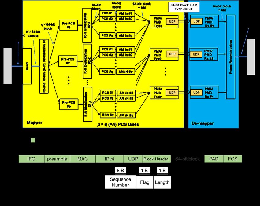
IEICE Communications Express, Vol.1, 1–6

 [5] R. D. Blumofe and C. E. Leiserson, “Scheduling multithreaded computations by
 work stealing,” Journal of the ACM, vol. 46, no. 5, p. 720–748, Sep. 1999.
 DOI:10.1145/324133.324234

1 Introduction
The ever-growing network traffic implies 10 Tbps class network interface card
(NIC) will be necessary. Although the transmission capacity of optical fibers has
increased so far, spatial division multiplexing (SDM) technologies such as multi-
core/multi-mode fibers are assumed to be essential, because there is a limitation
around 100 Tbps for a single core single-mode fiber [1]. SDM fibers have lots of
optical channels. Massively parallel transmission is attractive for realizing 10 Tbps
class NIC. We have proposed a dynamic media access control (MAC) concept [2,
3] to fully utilize SDM. In [2], we have determined the bottleneck to expand the
parallelism on Ethernet is the round-robin (R-R) mapper which distributes blocked
MAC signals to multiple physical coding sublayer (PCS) lanes. As the number of
PCS-lanes increases, one R-R cycle takes longer time or R-R circuit should be
driven by faster clock. To relax this bottleneck, we have introduced a sub-layer
before the PCS and added extra R-R mapper called “hierarchical round-robin
mapper (HRRM)”. HRRM makes the R-R cycle shorter, thus it can increase
parallelism. To verify HRRM’s effectiveness, we have developed a software-based
emulator. In this paper detailed emulator architecture and evaluation results are
presented.

2 Design of the software-based dynamic MAC emulator
10 Tbps class NICs on the server equipment are connected to the SDM network.
In the client side, sub-Tbps class NICs are required. We have determined 25 Gbps
granularity in the dynamic MAC which covers 25 Gbps in 1 lane to 10 Tbps in 400
lanes. The dynamic MAC will distribute MAC signals over up to 400 PCS-lanes
using HRRM.
 To implement HRRM, mechanism of 100 Gbps Ethernet (100GE) physical
layer which uses 5 Gbps × 20 PCS-lanes is applied. In 100GE, a reconciliation
sublayer (RS) produces 64-bit blocks from the received MAC frames. Next, the
64-bit blocks are distributed to 20 PCS-lanes in a R-R manner; multi-lane
distribution (MLD). Under MLD, each MAC frame is mapped to 20 × 64-bit
stream signal and the stream is distributed to each PCS-lane as a 64-bit block signal.
PCS adds a 2-bit header into each block. An alignment marker (AM) is periodically
inserted. Then, a physical medium attachment (PMA) performs bit multiplexing to
fit lanes of physical medium dependent (PMD).
 In 400 PCS-lanes with HRRM, MAC frames are treated as a N × 64-bit
stream (N = 400). The N × 64-bit stream is distributed to p Pre-PCSs as q × 64-bit
block signal (N =p × q) by 1st R-R distributor. Next, the Pre-PCS divides the q ×
64-bit block signal into q 64-bit block signals and distributed to q PCSs by 2nd R-
R distributor. A 66-bit block signal is generated in each PCS and AM is inserted.
In the current emulator design, the 2-bit header is omitted to add to a 64-bit block.
IEICE Communications Express, Vol.1, 1–6

This is because, in the emulator, blocks are transmitted by IPv4 packets. AM is not
periodically inserted but a sequence number is added to each 64-bit block as AM-
information. This can relax the receiver side processing for reconstructing the
MAC frame from received blocks. Total N 64-bit blocks with AM-information are
input to r PMAs and PMDs. Here, each 64-bit block is encapsulated into UDP/IPv4
packet and then r packets are transmitted to the receiver.
 Figure 1(a) shows a designed emulator architecture. Emulation is done on
multi-core CPU environment. The emulator is constructed with 5 processing
components, a sender, a mapper, a transmission network (omitted in Fig.1(a)), a
de-mapper, and a receiver. The sender sends an Ethernet frame stream to the
mapper. The mapper reads received frames and mapped to N PCS-lanes as 64-bit
block signals and sends them to r physical signals with AM-information. Each 64-
bit block is mapped into 46-byte UDP/IPv4 packet as shown in Fig.1(b). AM-
information is inserted as a 10-byte block-header. 2-byte padding (PAD) will be
done to make 48-byte minimum Ethernet payload. The packets are transmitted to
the de-mapper via the Ethernet-based transmission network. Ethernet transmission
requires additional overheads to the 64-bit block. They are 14-byte MAC header,
4-byte frame check sequence (FCS), 8-byte preamble, and minimum 12-byte inter
frame gap (IFG). One 64-bit block is converted to at least 88 bytes. In the de-
mapper, received packets are ordered by AM-information, and MAC frame is
reconstructed from received 64-bit blocks. The reconstructed frame is sent to the
receiver.

 Fig. 1. The design of the emulator. (a) Detailed design of the
 mapper and the de-mapper functions. (b) UDP/IPv4
 encapsulation design of the 64-bit block transmission.
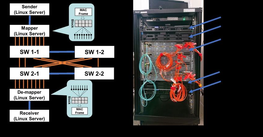
IEICE Communications Express, Vol.1, 1–6

 In the hardware implementation, both p Pre-PCSs and p 2nd R-R distributors
can be run in parallel. In the software implementation, multi-thread is applicable
to emulate the parallel processing. However, because of the large transmission
overhead and the software processing, end-to-end throughput of the emulator will
not be reached to 1 Gbps even if multi 10 Gbps Ethernet (10GE) interfaces are
assigned to PMA/PMDs.

3 Emulator implementation
Figure 2(a) shows a diagram of the emulator and Fig.2(b) shows a photograph. The
emulator is consists of four Linux-servers and four Ethernet switchies. Both the
sender and the receiver use Intel Xeon E3-1200 v6 (4 cores, 3.00 GHz) CPU with
16 GB memory and 40 Gbps Ethernet (40GE) NIC. They act as MAC frame
generator and consumer. Another two Linux-servers are assigned for the mapper
and the de-mapper which have two Intel Xeon Silver 4116 CPUs (12 cores, 2.10
GHz) with 64 GB memory and one 40GE NIC and eight 10GE NICs. Total 24
cores can be used for multi-thread parallel processing. 40GE link is set between
the sender and the mapper, and the de-mapper and the receiver. A parallel
transmission network is set between the mapper and de-mapper for parallel PMD
transmission.

 Fig. 2. The developed dynamic MAC emulator. (a) The diagram of
 the emulator. (b) The photograph of the emulator.

 The Rust language [4] and the lightweight thread [5] which is implemented at
the programming language level are applied to reduce the performance degradation
caused by software abstractions.
 In the mapper, the program is composed of multiple-threads, “R-
R_Distribution_#1”, “Pre-PCS_and_R-R_Distribution_#2”, “PCS_and_AM”,
and “PMA/PMD_lanes_Tx”. Parameters “p” , “q”, and “r” can be re-configurable.
In the without-HRRM case, the R-R_Distribution_#1 is directly connected to the
PCS_and_AM threads. Parameters of p=1 and q=N will act as almost the same
processing in the with-HRRP case.
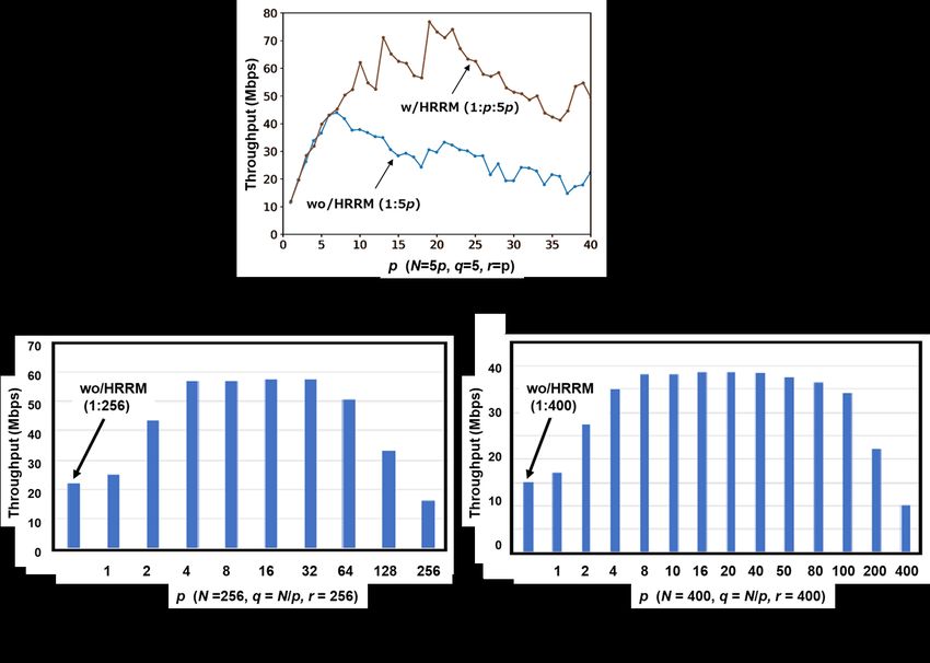
IEICE Communications Express, Vol.1, 1–6

 In the de-mapper, a MAC frame restoration program is implemented. Several
“PMA/PMD_lanes_Rx” threads receive 64-bit blocks from the mapper and pass
them to a “Frame_Reconstruction” thread. In the Frame_Reconstruction thread,
blocks are stored in a buffer and aligned by the block-header information. The
block-header contains an 8-byte sequence number, an 1-byte flag that indicated the
start or end of the client MAC frame, and an 1-byte field indicating a length of the
client MAC frame for reconstructing. As a result, the dynamic MAC emulator can
be seen real Ethernet equipment from the Ethernet MAC clients.

4 Experiments and discussion
First, we examined throughput between the sender and the receiver with and
without HRRM, while changing the parallelism in the small scale (N=5-200). The
iperf3 program in TCP mode is applied for evaluating the throughput. PCS-lanes
of without-HRRM is set 5p (N=5p, r=p), and PCS-lanes of with-HRRM is 5p (q=5,
N=5p, r=p). Figure 3(a) shows the throughput against parallelism parameter p. As
shown in Fig.3(a), in the without-HRRM case, maximum 44.4 Mbps throughput
at p=7 is observed. In the with-HRRM case, maximum 76.8 Mbps at p=19 is
observed. This indicated that the R-R_Distribution_#1 thread becomes a
bottleneck of the emulator. Theoretically, the parallelism should be extended ×5
in the with-HRRM case. However, as the CPU executes a limited number of
instructions simultaneously, the result was deteriorated. The result still indicates
the HRRM helps to expand parallelism.

 Fig. 3. TCP throughput evaluation results. (a) Smaller N cases
 (N=5p, p=1-40, q=5, r=p). (b) N=256 (p=1-256, q=N/p,
 r=256). (c) N=400 (p=1-400, q=N/p, r=400).
IEICE Communications Express, Vol.1, 1–6

 Second, the large parallelisms (N = 256 and 400) were examined. In these
evaluations, we found that the CPU utilization became large (over 1,000 %) and
many threads were concurrently on all CPU cores. Throughput evaluation results
are shown in Fig.3(b) and (c). In the without-HRRM, the R-R_Distribution_#1
thread should process the block distribution to 256 or 400 PCS_and_AM threads,
this processing latency becomes a bottleneck to restrict throughput around 20
Mbps. In the with-HRRM, p=1 (q=256 or 400) indicated the almost same
performance as the without-HRRM. Theoretically, p = 256 and 400 cases also
presented the same results. However, in this evaluation, less performance results
were observed. We think that this is caused by the thread synchronization overhead
among threads. As shown in Fig.3(b) and (c), in with-HRRM cases, the higher the
p, the higher the throughput performance until p=16. The developed emulator did
not emulate the hardware clock specification of each function of the mapper.
Therefore, this is true that parameters of ≈ ≈ √ will provide the maximum
performance.
 Applying much more CPU cores for emulation processing will realize the
performance enhancement of the emulator and introducing the hardware clock
emulation to each thread will provide precise emulated hardware environment on
the software-based system.

5 Conclusion
We developed the dynamic MAC emulator which supports 400 parallel lanes with
HRRM. The experimental results showed that the HRRM could expand the
transmission throughput compared to the without-HRRM even in the software-
based emulator environment.

Acknowledgments
This work is partly supported by the “Massively Parallel and Sliced Optical
Network (MAPLE)” project funded by the National Institute of Information and
Communications Technology (NICT), Japan.
You can also read