HM500 Instruction Manual - TOUCH TERMINALS - Panasonic
←
→
Page content transcription
If your browser does not render page correctly, please read the page content below
TOUCH TERMINALS

                                                   HM500
                                              Instruction Manual

ACGM0194V2EN Version 2.0

2021.04       https://industry.panasonic.eu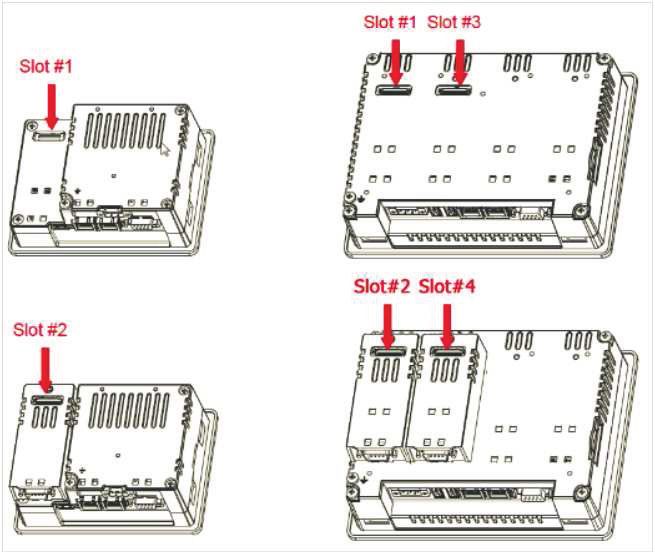
Table of contents
1.     Introduction....................................................................................................................................3

2.     Product overview...........................................................................................................................4

3.     Standards and approvals..............................................................................................................5

4.     Product identification....................................................................................................................6

5.     Technical data common to all models..........................................................................................7
       5.1 Hardware specifications.........................................................................................................7
       5.2 Environmental conditions.......................................................................................................7
       5.3 Electromagnetic compatibility (EMC).....................................................................................8
       5.4 Durability information.............................................................................................................8
       5.5 Viewing angles.......................................................................................................................8

6.     Technical data by model................................................................................................................9

7.     Dimensions...................................................................................................................................10
       7.1 HM504..................................................................................................................................10
       7.2 HM507, HM510, HM513...................................................................................................... 11

8.     Installation ...................................................................................................................................12
       8.1 Installation environment.......................................................................................................12
       8.2 Applying the gasket..............................................................................................................12
       8.3 Installation procedure...........................................................................................................13

9.     Connections..................................................................................................................................14
       9.1 HM504..................................................................................................................................14
       9.2 HM507, HM510 and HM513................................................................................................14
       9.3 Serial port.............................................................................................................................15
       9.4 Ethernet port........................................................................................................................15
       9.5 Optional plug-ins..................................................................................................................16
       9.6 Power supply, grounding, and shielding ..............................................................................17

10. Battery...........................................................................................................................................18

11. Cleaning faceplates......................................................................................................................18

12. Getting started..............................................................................................................................18

13. System settings tool ...................................................................................................................19
    13.1 Introduction..........................................................................................................................19
    13.2 Options available in user mode ...........................................................................................20
    13.3 Options available in system mode ......................................................................................20

14. LED indicator on the front...........................................................................................................21

15. Unpacking and packing instructions.........................................................................................21

16. Record of changes.......................................................................................................................22

                                                                           2
Introduction
1. Introduction
This instruction manual contains information about the installation, transportation, storage, assembly,
use and maintenance of programmable displays of the HM500 series.
The following models are available:
• HM504: Programmable display with TFT color 4.3” display touchscreen
• HM507: Programmable display with TFT color 7” widescreen display touchscreen
• HM510: Programmable display with TFT color 10.4” display touchscreen
• HM513: Programmable display with TFT color 13.3” widescreen display touchscreen
3Product overview
2. Product overview
The HM500 series programmable displays combine state-of-the-art features and top performance with
an oustanding design. They are the ideal choice for all demanding HMI applications including factory
and building automation.
The HM500 series programmable displays have been designed to run the HMWIN software.
● HMWIN runtime included. Full compatibility with HMWIN Studio.
● Full vector graphic support. Native support of SVG graphic objects. Trasparency and alpha blend-
ing.
● Full object dynamics: control visibility and transparency, move, resize, rotate any object on screen.
Change properties of basic and complex objects.
● TrueType fonts.
● Multilanguage applications. Easily create and manage your applications in multiple languages to
meet global requirements. Far East languages are supported. Tools available in HMWIN Studio
support easy third-party translations and help reducing development and maintenance costs of the
application.
● Data display in numerical, text, bargraph, analog gauges and graphic image formats.
● Rich set of state-of-the-art HMI features: data acquisition, alarm handling, scheduler and timed
actions (daily and weekly schedulers, exception dates), recipes, users and passwords, RSS feeds,
rotating menus.
● Multiple drivers communication capability.
● Remote monitoring and control. Client-Server functionality.
● Off-line simulation with HMWIN Studio.
● Powerful scripting language for automating HMI applications. Script debugging improves efficiency
in application development.
● Rich gallery of vector symbols and objects.
● Project templates.
● Optional plug-in modules.
4Standards and approvals
3. Standards and approvals
The products have been designed for use in an industrial environment in compliance with the
2004/108/EC EMC Directive.
The products have been designed in compliance with:
EN 61000-6-4 EN 55011 Class A
EN 61000-6-2 EN 61000-4-2
EN 61000-4-3
EN 61000-4-4
EN 61000-4-5
EN 61000-4-6
EN 61000-4-8
The installation of these devices into the residential, commercial and light-industrial environments
is allowed only in the case that special in measures are taken in order to ensure conformity to
EN 61000-6-3.
The products are in compliance with the Restrictions on Certain Hazardous Substances (RoHS)
Directive 2011/65/EC
In compliance with the above regulations the products are CE marked.
5Product identification
4. Product identification
The product may be identified through a plate attached to the rear cover. You will have to know the
type of unit you are using for correct usage of the information contained in the guide.
The following information is provided by the plate:
● Product model name
● Product part number
● Month/year of production
● Serial number
● Version ID of the product
6Technical data common to all models
5. Technical data common to all models
5.1 Hardware specifications
Touch screen technology Resistive
Back-up battery 3V 50mAh Lithium, rechargeable, not user-replaceable, model
VL2330.
Fuse Automatic
Serial Port RS232, RS485, RS422 software configurable
User memory • Flash 128Mb for HM504 and HM507
• Flash 256Mb for HM510 and HM513
Recipe memory Flash
Real-time clock Clock/Calendar with backup battery
Accuracy real-time clockTechnical data common to all models
5.3 Electromagnetic compatibility (EMC)
Radiated disturbance test Class A EN 55011
Electrostatic discharge immunity test 8kV (air electrostatic discharge) EN 61000-4-2
4kV (contact electrostatic discharge)
Radiated, radio-frequency, 80MHz – 1GHz, 10V/m EN 61000-4-3
electromagnetic field immunity test 1,4GHz – 2GHz, 3V/m
2GHz – 2.7GHz, 1V/m
Burst immunity test ± 2KV DC power port EN 61000-4-4
± 1KV signal line
Surge immunity test ± 0,5KV DC power port (line to earth) EN 61000-4-5
± 0,5KV DC power port (line to line)
± 1KV signal line (line to earth)
Immunity to conducted disturbances 0.15 – 80 MHz, 10V EN 61000-4-6
inducted by radiofrequency field
5.4 Durability information
Backlight service life (LED type) 40000 hours or more (Time of continuos operation until the
brightness of the backlight reaches 50% of the rated value
when the surrounding air temperature is 25°C, see note 1)
Front foil (without direct 10 years if the surrounding air temperature is 25°C
exposure to sunlight or UV rays)
UV resistance Indoor applications: After 300 hours cycled humidity in QUV
accelerated weathering, some yellowing and brittleness may
be present (see note 2).
Touch screen reliability > 1 milion operations
1. Extended use in environments where the surrounding air temperature is 40°C or higher may degrade backlight
quality/reliability/durability.
2. Solvent resistance:
Contact for 1/2 hour at 21°C, no visible effect: acetone, butyl cellosolve, cyclohexanone, ethyl acetate, hexane,
isopropyl alcohol, mek, methylene chloride, toluene, xylene
Contact for 24 hours at 49°C, no visible effect: coffee, ketchup, lemon juice, mustard (slight yellow stain), tea,
tomato juice.
5.5 Viewing angles
The viewing angles for the horizontal (L, R) and vertical (U, D) axes are specified in reference to the
vertical axis of the display. The viewing angles always refer to the standard mounting orientation.
For the viewing angle values (U, D ,R ,L), refer to the technical data of the respective touch terminal
model.
U: From top D: From bottom
L: From left R: From right
8Technical data by model
6. Technical data by model
Model HM504 HM507
Display / Backlight TFT Color / LED
Colors 64K
Resolution 480x272 800x480
Display size (inch) 4.3” 7” widescreen
Dimming yes
Horizontal viewing angle L/R: typ. 50° L/R: typ. 65°
Vertical viewing angle U: typ. 45°, D: typ. 50° U: typ. 55°, D: typ. 65°
User memory flash 128MB
SD card slot yes
Recipe memory Yes. Flash memory storage limited only by available memory
Serial port RS232, RS485, RS422 DB9 female software configurable
Ethernet port 2 10/100Mbit with integrated switch
USB port 1 Host interface version 2.0 and 1.1 2 Host interfaces, 1 version 2.0,
1 version 2.0 and 1.1
Expansion slot 1 Optional plug-in 2 Optional plug-ins
Battery rechargeable
Real-time clock yes
Voltage 10–32V DC (see note)
Current rating (at 24V DC) 0.4A 0.65A
Weight 1kg 1kg
Model HM510 HM513
Display / Backlight TFT Color / LED
Colors 64K
Resolution 800x600 1280x800
Display size (inch) 10.4 widescreen 13.3” widescreen
Dimming yes
Horizontal viewing angle L/R: typ. 80° L/R: typ. 70°
Vertical viewing angle U/D: typ. 70° U/D: typ. 60°
User memory flash 256MB
SD card slot yes
Recipe memory Yes. Flash memory storage limited only by available memory
Serial port RS232, RS485, RS422 DB9 female software configurable
Ethernet port 2 10/100Mbit with integrated switch
USB port 2 Host interfaces, 1 version 2.0, 1 version 2.0 and 1.1
Expansion slot 2 Optional plug-ins
Battery rechargeable
Real-time clock yes
Voltage 10–32V DC (see note)
Current rating (at 24V DC) 1A 1.2A
Weight 2.1kg 2.8kg
* For applications requiring compliance with EN 61131-2 and specifically in reference to 10ms voltage dips, the
minimum power supply voltage is 18V DC.
9Dimensions
7. Dimensions
7.1 HM504
Cutout
Model A B C D E F
HM504 149mm 109mm 136mm 96mm 56mm 4mm
10Dimensions
7.2 HM507, HM510, HM513
Cutout
Model A B C D E F
HM507 187mm 147mm 176mm 136mm 47mm 4mm
HM510 287mm 232mm 276mm 221mm 56mm 4mm
HM513 336mm 267mm 326mm 256mm 56mm 4mm
11Installation
8. Installation
8.1 Installation environment
The equipment is not intended for continuous exposure to direct sunlight. This might accelerate the
aging process of the front panel film.
The equipment is not intended for installation in contact with corrosive chemical compounds. Check
the resistance of the front panel film to a specific compound before installation.
Do not use tools of any kind (screwdrivers, etc.) to operate the touch screen of the panel.
In order to meet the front panel degree of protection if the following requirements are met:
• The borders of the cutout must be flat
• Each fixing screw must be tightened until the plastic bezel corner get in contact with the panel.
• The cutout for the panel must be of the dimensions indicated in this manual.
The IP66 is guaranteed only if:
• The max. deviation from the plane surface to the cut-out is ≤0.5mm
• The thickness of the case where the equipment is mounted is from 1.5mm to 6mm
• The max. surface roughness where the gasket is applied is ≤120um.
8.2 Applying the gasket
The gasket should be applied on the rear of the frame.
HM504, HM507 HM510, HM513
A: Gasket
B: Installation cutout
12Installation
8.3 Installation procedure
Place the fixing brackets as shown in the figure below.
Make sure to screw each fixing screw until the bezel corner gets in contact with the panel.
13Connections
9. Connections
9.1 HM504
1 Serial port
2 2x Ethernet port
3 USB port
4 Power supply
5 Expansion slot for plug-ins
6 SD card slot
9.2 HM507, HM510 and HM513
1 Serial port
2 2x Ethernet port
3 2x USB port
4 Power supply
5 2x Expansion slot for plug-ins
6 SD card slot
14Connections
9.3 Serial port
The serial port is used to communicate with the PLC or with another type of controller.
Different electrical standards are available for the signals in the PLC port connector: RS232, RS422,
RS485. Use the corresponding communication cable for the connection.
The serial port is software programmable. Make sure you select the appropriate interface in the pro-
gramming software.
RS232 RS422, RS485
Pin Description Pin Description
1 GND 1 GND
2 2
3 TX Serial port 3 CHA-
4 RX 4 CHB-
5 5
6 +5V output 6 +5V output
7 CTS 7 CHB+
8 RTS 8 CHA+
9 9
For RS485, pins 4-3 and 8-7
must be connected externally.
9.4 Ethernet port
The Ethernet ports have two status indicators. They work as shown in the picture below.
OFF: Valid link has NOT been detected ON: No activity
ON: Valid link has been detected BLINKING: Activity
15Connections
9.5 Optional plug-ins
There are several optional plug-ins available for the HM500 series. Depending on the panel type, there
are one or two expansion slots.
Slot #2 and slot #4 are available only if the plugin module is equipped with the bus extension connector.
Module Application Max. No. of plug-ins Bus extension connector
PLCM03 Serial RS232 2 Yes
PLCM04 Serial RS485 2 Yes
If you are planning to use PLCM03 and PLCM04 (additional serial ports), the COM port numbers will
be assigned as follows:
● A module plugged in slot #1 or slot #2 will be COM2,
● A module plugged in slot #3 or slot #4 will be COM3.
16Connections
9.6 Power supply, grounding, and shielding
The power supply terminal block is shown in the figure below.
+24V
Common
NOTICE
Make sure that the power supply has sufficient power capacity for the operation of the equipment.
The unit must always be grounded to earth. Grounding helps limit the effects of noise due to electro-
magnetic interference on the control system.
Earth connection will have to be done using either the screw or the faston terminal located near the
power supply terminal block. A label helps identify the ground connection. Also ground the terminal 3
on the power supply terminal block.
The power supply circuit may be floating or grounded. In the latter case, connect to ground the power
source common as indicated with a dashed line in the figure below.
When using the floating power scheme, note that internally the power common is connected to the
ground with a 1MΩ resistor in parallel with a 4,7nF capacitor.
The power supply must have double or reinforced insulation. The suggested wiring for the power sup-
ply is shown below.
HM5xx
All the electronic devices in the control system must be properly grounded. Grounding must be per-
formed according to applicable regulations.
17Battery
10. Battery
The touch panels are equipped with rechargeable Lithium batteries that are not user-replaceable. The
battery is needed to keep the real-time clock running (date and time).
When the touch panel is installed for the first time, the battery must be charged for 48 hours. When the
battery is fully charged, data backup at 25°C is guaranteed for 3 months.
Battery
HM504 HM507, HM510, HM513
NOTICE
Dispose of batteries according to local regulations.
11. Cleaning faceplates
The equipment must be cleaned only with a soft cloth and neutral soap product. Do not use solvents.
12. Getting started
The HM500 series panels must be programmed with the programming software HMWIN Studio, a
Windows application. To program a panel you will have to connect the panel via the Ethernet interface
to a personal computer running the HMWIN Studio software.
Make sure that the firewall policy is configured in a way that allows HMWIN Studio to access the
network. The version of the HMWIN Studio used must be compatible with the HMWIN runtime version
installed on the panel to be programmed.
18System settings tool
13. System settings tool
13.1 Introduction
The panels have a system settings tool to allow basic and preliminary settings. The system settings
tool comes in the shape of a rotating menu with navigation buttons at the top and the bottom to move
between the available options. The tool is shown in the picture below.
On the left side, a component or functions is highlighted. The right side shows information about the
current version, when applicable. The picture below shows the version of the Main OS component.
The system settings tool has two operating modes:
• User mode and
• System mode.
The difference between them is only in the number of available options.
To activate the system settings in user mode, you need to access the context menu by touching and
holding any unused area of the touchscreen for a few seconds. The default holding time is 2 seconds
and can be changed.
To activate the system settings in system mode, you need to tap the middle of the touchscreen re-
peatedly at a high frequency while the system is powering up. This only works during power-up.
19System settings tool
13.2 Options available in user mode
User mode is the simplest possible interface, where a generic user can get access to the basic set-
tings of the panel:
Calibrate touch Allows to calibrate the touch screen interface
Network Allows to change the options of the panel on-board network card
Time Allows to change the real-time clock options including time zone and DST
Display settings Automatic backlight turnoff and brightness adjustment
BSP settings Allows to check the BSP (Board Support Package) version (e.g. 2.37), the op-
erating hours timers for both the unit and backlight, enable/disable the buzzer,
enable/disable the use of the “low battery” front LED indicator
Plugin list Allows to check whether optional plugin modules are installed
13.3 Options available in system mode
System mode is the complete interface of the system settings tool where all options are available. In
addition to the options listed under “13.2 Options available in user mode” on page 20, the following
important options are available:
Format Flash Allows to format the internal panel flash disk
Resize Image Area Allows to resize the flash portion reserved to store the splash
screen image displayed by the unit at power-up; default settings
are normally ok for all the units
Download Configuration OS Allows to check current version and upgrade the backup operating
system.
Download Main OS Allows to check current version and upgrade the main operating
system
Download Splash Image Allows to change the splash screen image displayed by the unit at
power up. The image needs to be in a specific format. We suggest
to update the image directly from the HMWIN Studio software,
which supports this feature starting from version 1.50
Download Bootloader Allows to check the current version of the system boot loader and
to upgrade it
Only for HM510 and HM513
Download Main FPGA Allows to check the current version and upgrade the main FPGA
firmware
Download Safe FPGA Allows to check the current version and upgrade the backup
(safe) copy of the FPGA firmware,
Download System Supervisor Allows to check the current version and upgrade the system
supervisor firmware responsible for the real-time clock and the
handling of the power supply handling,
Note: the system settings tool includes also other options that are not described and not documented
in this manual.
20LED indicator on the front
14. LED indicator on the front
The table below shows how the LED indicator works.
Symbol Color State Meaning
red ON Hardware fault or battery low
green ON Normal operation
Flashing Communication error
15. Unpacking and packing instructions
1 2 3
To repack the unit, please follow the instructions backwards.
21Record of changes
16. Record of changes
Manual No. Date Description of changes
ACGM0194V1EN September 2014 First edition based on UniOP eTOP Series 500 Oper-
ating Instructions Ver. 1.07
ACGM0194V2EN April 2021 Second edition
• Added record of changes
• Added information about the viewing angles of
the displays
• Updated website URL
• Updated back page
Distributed by Panasonic Electric Works Europe AG
https://industry.panasonic.eu/
Copyright © 2011-2021 Exor International S.p.A. – Verona, Italy
Subject to change without notice
The information contained in this document is provided for informational purposes only. While efforts
were made to verify the accuracy of the information contained in this documentation, it is provided “as
is” without warranty of any kind.
Third-party brands and names are the property of their respective owners.
www.uniop.com
22Global Network
Global Network
North America Europe Asia Pacific China Japan
Panasonic Electric Works
Please contact our Global Sales Companies in:
Europe
▸ Headquarters Panasonic Electric Works Europe AG Caroline-Herschel-Strasse 100, 85521 Ottobrunn, Tel. +49 89 45354-1000, Fax +49 89 45354-1550, www.panasonic-electric-works.com
▸ Austria Panasonic Industry Austria GmbH Josef Madersperger Str. 2, 2362 Biedermannsdorf, Tel. +43 (0) 2236-26846, Fax +43 (0) 2236-46133
www.panasonic-electric-works.at
Panasonic Industrial Devices Materials Ennshafenstraße 30, 4470 Enns, Tel. +43 (0) 7223 883, Fax +43 (0) 7223 88333, www.panasonic-electronic-materials.com
Europe GmbH
▸ Benelux Panasonic Electric Works De Rijn 4, 5684 PJ Best, Netherlands, Tel. +31 (0) 499 372727, www.panasonic-electric-works.nl
Sales Western Europe B.V.
▸ Czech Republic Panasonic Electric Works Europe AG, Administrative centre PLATINIUM, Veveří 3163/111, 616 00 Brno, Tel. +420 541 217 001, Fax +420 541 217 101,
organizační složka www.panasonic-electric-works.cz
▸ France Panasonic Electric Works Succursale française, 10, rue des petits ruisseaux, 91370 Verrières Le Buisson, Tél. +33 (0) 1 6013 5757, Fax +33 (0) 1 6013 5758,
Sales Western Europe B.V. www.panasonic-electric-works.fr
▸ Germany Panasonic Electric Works Europe AG Caroline-Herschel-Strasse 100, 85521 Ottobrunn, Tel. +49 89 45354-1000, Fax +49 89 45354-2111, www.panasonic-electric-works.de
▸ Hungary Panasonic Electric Works Europe AG Magyarországi Fióktelepe, 1117 Budapest, Alíz utca 4, Tel. +43 (0) 2236 26846 -25, Fax +43 (0) 2236 46133
www.panasonic-electric-works.hu
▸ Ireland Panasonic Electric Works UK Ltd. Irish Branch Office, Dublin, Tel. +353 (0) 14600969, Fax +353 (0) 14601131, www.panasonic-electric-works.co.uk
▸ Italy Panasonic Industry Italia srl Via del Commercio 3-5 (Z.I. Ferlina), 37012 Bussolengo (VR), Tel. +39 0456752711, Fax +39 0456700444,
www.panasonic-electric-works.it
▸ Nordic Countries Panasonic Electric Works Europe AG Filial Nordic, Knarrarnäsgatan 15, 164 40 Kista, Sweden, Tel. +46 859476680, Fax +46 859476690, www.panasonic-electric-works.se
Panasonic Fire & Security Europe AB Jungmansgatan 12, 21119 Malmö, Tel. +46 40 697 7000, Fax +46 40 697 7099, www.panasonic-fire-security.com
▸ Poland Panasonic Industry Poland sp. z o.o. Ul. Dowborczyków 25, 90-019 Lódź, Polska, Tel. +48 42 2309633, www.panasonic-electric-works.pl
▸ Spain Panasonic Industry Iberia S.A. Barajas Park, San Severo 20, 28042 Madrid, Tel. +34 913293875, Fax +34 913292976, www.panasonic-electric-works.es
▸ Switzerland Panasonic Industry Switzerland AG Grundstrasse 8, 6343 Rotkreuz, Tel. +41 (0) 41 7997050, Fax +41 (0) 41 7997055, www.panasonic-electric-works.ch
▸ United Kingdom Panasonic Electric Works UK Ltd. Sunrise Parkway, Linford Wood, Milton Keynes, MK14 6 LF, Tel. +44 (0) 1908 231555, Fax +44 (0) 1908 231599,
www.panasonic-electric-works.co.uk
North & South America
▸ USA Panasonic Industrial Devices Sales Company Two Riverfront Plaza, 7th Floor, Newark, NJ 07102-5490, Tel. 1-8003-442-112, www.pewa.panasonic.com
of America
Asia Pacific / China / Japan
▸ China Panasonic Electric Works Sales (China) Co. Ltd. Tower C 3rd Floor, Office Park, NO.5 Jinghua South Street, Chaoyang District, Beijing 100020, Tel. +86-10-5925-5988,
Fax +86-10-5925-5980
▸ Hong Kong Panasonic Industrial Devices Sales (HK) Co., Suite 301, 3/F, Chinachem Golden Plaza, 77 Mody Road, TST East, Kowloon, Hong Kong, Tel. +852-2529-3956, Fax +852-2528-6991
Ltd.
▸ Japan Panasonic Corporation 1006, Oaza Kadoma, Kadoma-shi, Osaka 571-8501, Japan, Tel. +81-6-6908-1121, www.panasonic.net
▸ Singapore Panasonic Industrial Devices No.3 Bedok South Road, Singapore 469269, Tel. +65-6299-9181, Fax +65-6390-3953
Automation Controls Sales Asia Pacific
ACGM0194V2EN Version 2.0 4/2021
Copyright © 2021 Panasonic Electric Works Europe AGYou can also read