Hydraulic ring force transducers - Geotechnical version Models F6137, F6148, F6160, F6171 Hydraulische Ringkraftaufnehmer - Geotechnik-Ausführung ...
←
→
Page content transcription
If your browser does not render page correctly, please read the page content below

Operating instructions
                                    Betriebsanleitung
Hydraulic ring force transducers - Geotechnical version
                                                             EN
Models F6137, F6148, F6160, F6171
Hydraulische Ringkraftaufnehmer - Geotechnik-Ausführung
                                                             DE
Typen F6137, F6148, F6160, F6171

                         Model F6137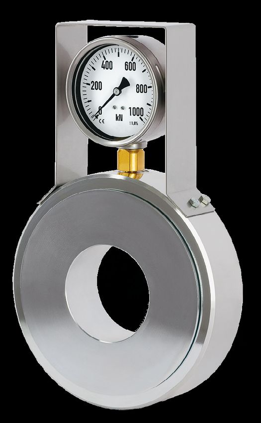
EN   Operating instructions models F6137, F6148, F6160, F6171                         Page       3 - 32

DE   Betriebsanleitung Typen F6137, F6148, F6160, F6171                               Seite     33 - 63

                                                                                                          ADPR1X914115.01 10/2020 EN/DE

     © 10/2020 WIKA Alexander Wiegand SE & Co. KG
     All rights reserved. / Alle Rechte vorbehalten.
     WIKA® and tecsis® are registered trademarks in various countries.
     WIKA® and tecsis® sind geschützte Marken in verschiedenen Ländern.

     Prior to starting any work, read the operating instructions!
     Keep for later use!

     Vor Beginn aller Arbeiten Betriebsanleitung lesen!
     Zum späteren Gebrauch aufbewahren!

      2                                       Operating instructions, models F6137, F6148, F6160, F6171
Contents

                                Contents
                                1. General information                                                                                         4
                                2. Design and function                                                                                         5
                                    2.1 Overview  .   .   .   .   .   .   .   .   .   .   .   .   .   .   .   .   .   .   .   .   .   .   . 5
                                    2.2 Description . . . . . . . . . . . . . . . . . . . . . . . 6                                                EN
                                    2.3 Scope of delivery  .  .  .  .  .  .  .  .  .  .  .  .  .  .  .  .  .  .  .  . 6
                                3. Safety                                                                                                      6
                                    3.1 Explanation of symbols  .  .  .  .  .  .  .  .  .  .  .  .  .  .  .  .  .  . 6
                                    3.2 Intended use  .  .  .  .  .  .  .  .  .  .  .  .  .  .  .  .  .  .  .  .  .  . 7
                                    3.3 Improper use  .   .   .   .   .   .   .   .   .   .   .   .   .   .   .   .   .   .   .   .   .   . 8
                                    3.4 Responsibility of the operator   .   .   .   .   .   .   .   .   .   .   .   .   .   .   .   . 8
                                    3.5 Personnel qualification  .   .   .   .   .   .   .   .   .   .   .   .   .   .   .   .   .   .   . 9
                                    3.6 Personal protective equipment  .   .   .   .   .   .   .   .   .   .   .   .   .   .   .   . 9
                                    3.7 Labelling, safety marks  .  .  .  .  .  .  .  .  .  .  .  .  .  .  .  .  .  . 10
                                4. Transport, packaging and storage                                                                           11
                                    4.1 Transport  .   .   .   .   .   .   .   .   .   .   .   .   .   .   .   .   .   .   .   .   .   .   . 11
                                    4.2 Packaging and storage  .  .  .  .  .  .  .  .  .  .  .  .  .  .  .  .  .  . 11
                                5. Commissioning, operation                                                                                   12
                                    5.1 Mounting preparation  .  .  .  .  .  .  .  .  .  .  .  .  .  .  .  .  .  .  . 12
                                    5.2 Mounting instructions  .  .  .  .  .  .  .  .  .  .  .  .  .  .  .  .  .  .  . 12
                                    5.3 Mounting of the hydraulic ring force transducer  .  .  .  .  .  .  .  .  .  . 13
                                    5.4 Commissioning of the hydraulic ring force transducer with digital pressure
                                        gauge   .   .   .   .   .   .   .   .   .   .   .   .   .   .   .   .   .   .   .   .   .   .   .   . 15
                                    5.5 Electrical connection - Hydraulic ring force transducer with pressure sensor 17
                                6. Faults                                                                                                     18
                                    6.1 Faults of the hydraulic ring force transducer with pressure gauge/digital
                                        pressure gauge  .  .  .  .  .  .  .  .  .  .  .  .  .  .  .  .  .  .  .  .  . 18
                                    6.2 Faults of the hydraulic ring force transducer with pressure sensor  .  .  .  . 19
                                7. Maintenance and cleaning                                                                                   20
                                    7.1 Maintenance  .  .  .  .  .  .  .  .  .  .  .  .  .  .  .  .  .  .  .  .  .  . 20
                                    7.2 Cleaning  .  .  .  .  .  .  .  .  .  .  .  .  .  .  .  .  .  .  .  .  .  .  . 20
                                    7.3 Recalibration  .   .   .   .   .   .   .   .   .   .   .   .   .   .   .   .   .   .   .   .   .  20
                                8. Dismounting, return and disposal                                                                           21
                                    8.1 Dismounting  .  .  .  .  .  .  .  .  .  .  .  .  .  .  .  .  .  .  .  .  .  . 21
ADPR1X914115.01 10/2020 EN/DE

                                    8.2 Return  .   .   .   .   .   .   .   .   .   .   .   .   .   .   .   .   .   .   .   .   .   .   .   . 21
                                    8.3 Disposal  .  .  .  .  .  .  .  .  .  .  .  .  .  .  .  .  .  .  .  .  .  .  . 21
                                9. Specifications                                                                                             22
                                    9.1 Approvals  .  .  .  .  .  .  .  .  .  .  .  .  .  .  .  .  .  .  .  .  .  .  . 30
                                10. Accessories                                                                                               30
                                    10.1 Cables .   .   .   .   .   .   .   .   .   .   .   .   .   .   .   .   .   .   .   .   .   .   .  30
                                Annex: EU declaration of conformity                                                                           31

                                Operating instructions, models F6137, F6148, F6160, F6171                                                     3
1. General information

     1. General information
     ■ The hydraulic ring force transducers described in the operating instructions have
          been designed and manufactured using state-of-the-art technology. All components
EN        are subject to stringent quality and environmental criteria during production. Our
          management systems are certified to ISO 9001.
     ■    These operating instructions contain important information on handling the instru-
          ment. Working safely requires that all safety instructions and work instructions are
          observed.
     ■    Observe the relevant local accident prevention regulations and general safety regula-
          tions for the instrument's range of use.
     ■    The operating instructions are part of the product and must be kept in the immediate
          vicinity of the instrument and readily accessible to skilled personnel at any time. Pass
          the operating instructions on to the next operator or owner of the instrument.
     ■    Skilled personnel must have carefully read and understood the operating instructions
          prior to beginning any work.
     ■    The general terms and conditions contained in the sales documentation shall apply.
     ■    Subject to technical modifications.
     ■    Factory calibrations/DKD/DAkkS calibrations are carried out in accordance with
          international standards.

     Further information:
        - Internet address:              www.wika.de
        - Relevant data sheet:           FO 52.20 - F6137
                                         FO 52.21 - F6148
                                         FO 52.22 - F6160
                                         FO 52.23 - F6171

          - Application consultant:      Tel.: +49 9372 132-0
                                         Fax: +49 9372 132-406
                                         info@wika.de

     Abbreviations, definitions
     2-wire     The two connection lines are used for the voltage supply.
                The measuring signal also provides the supply current.
     3-wire     Two connection lines are used for the voltage supply.
                One connection line is used for the measuring signal.
                                                                                                     ADPR1X914115.01 10/2020 EN/DE

     UB+        Positive power supply terminal
     UB-        Negative power supply terminal
     S+         Positive output terminal
     S-         Negative output terminal

      4                                 Operating instructions, models F6137, F6148, F6160, F6171
2. Design and function
2. Design and function
2.1 Overview
EN
Hydraulic ring force transducer consisting of:
Pressure measuring instrument (pressure gauge or pressure sensor)
Adapter
Measuring piston case
Measuring piston (force introduction)
Electrical connection
Guard bracket
Hydraulic ring force transducer Hydraulic ring force transducer
with mounted pressure gauge with mounted pressure sensor
ADPR1X914115.01 10/2020 EN/DE
Operating instructions, models F6137, F6148, F6160, F6171 5
2. Design and function / 3. Safety

     2.2 Description

     Hydraulic ring force transducers are designed for measuring static and dynamic
     compression forces. They comprise an hydraulic force transducer and a mounted
EN   pressure measuring instrument (pressure gauge, pressure sensor).

     The measuring body is manufactured from galvanised steel. The force acting on the
     measuring piston is transmitted as pressure, proportional to the piston area, via the fill
     fluid in the measuring piston to the pressure measuring instrument.

     2.3 Scope of delivery

     ■ Hydraulic ring force transducer incl. mounted pressure measuring instrument
     ■ Operating instructions

     3. Safety
     3.1 Explanation of symbols

                   WARNING!
                   ... indicates a potentially dangerous situation that can result in serious
                   injury or death, if not avoided.

                   CAUTION!
                   ... indicates a potentially dangerous situation that can result in light injuries
                   or damage to property or the environment, if not avoided.

                   Information
                   ... points out useful tips, recommendations and information for efficient
                   and trouble-free operation.
                                                                                                       ADPR1X914115.01 10/2020 EN/DE

      6                                Operating instructions, models F6137, F6148, F6160, F6171
3. Safety

                                3.2 Intended use

                                The hydraulic ring force transducers are designed for static and dynamic compression
                                forces in the field of geotechnology for measuring anchor forces.
                                                                                                                           EN
                                 Model                Nominal size        Rated force
                                 F6137                NS 82               0 ... 80 kN to 0 ... 700 kN
                                 F6148                NS 146              0 ... 150 kN to 0 ... 1,500 kN
                                 F6160                NS 383              0 ... 400 kN to 0 ... 3,200 kN
                                 F6171                NS 827              0 ... 800 kN to 0 ... 6,000 kN

                                Applies to the hydraulic ring force transducer with mounted pressure sensor:

                                The instrument has been designed and tested in accordance with the relevant safety
                                regulations for electronic measuring instruments. Any usage outside of this is deemed to
                                be improper. The perfect functioning and operational safety of the force transducers can
                                only be guaranteed when complying with the instructions given in the operating instruc-
                                tions. During its use, the legal and safety regulations (e.g. VDE 0100) required for the
                                particular application must additionally be observed. This also applies accordingly when
                                using accessories. Faultless and safe operation of this measuring unit requires proper
                                transport, professional storage, installation and mounting and careful operation and
                                corrective maintenance.

                                The instrument has been designed and built solely for the intended use described here,
                                and may only be used accordingly.

                                The technical specifications contained in these operating instructions must be
                                observed. Improper handling or operation of the instrument outside of its technical
                                specifications requires the instrument to be taken out of service immediately and
                                inspected by an authorised service engineer.
ADPR1X914115.01 10/2020 EN/DE

                                 Operating instructions, models F6137, F6148, F6160, F6171                            7
3. Safety

     Handle electronic precision measuring instruments with the required care (protect from
     humidity, impacts, strong magnetic fields, static electricity and extreme temperatures,
     do not insert any objects into the instrument or its openings). Plugs and sockets must be
     protected from contamination.
EN
     The manufacturer shall not be liable for claims of any type based on operation contrary
     to the intended use.

     3.3 Improper use

                   WARNING!
                   Injuries through improper use
                   Improper use of the instrument can lead to hazardous situations and
                   injuries.
                   ▶ Refrain from unauthorised modifications to the instrument.

     Any use beyond or different to the intended use is considered as improper use.

     3.4 Responsibility of the operator

     The instrument is used in the industrial sector. The operator is therefore responsible for
     legal obligations regarding occupational safety.

     The safety instructions within these operating instructions, as well as the safety,
     accident prevention and environmental protection regulations for the application area of
     the instrument must be maintained.

     The operator is obliged to maintain the product label in a legible condition.

     To ensure safe working on the instrument, the operating company must ensure
     ■ that suitable first-aid equipment is available and aid is provided whenever required.
     ■ that the skilled electrical personnel are regularly instructed in all topics regarding
        occupational safety, first aid and environmental protection and know the operating
        instructions and in particular, the safety instructions contained therein.
     ■ that the instrument is suitable for the particular application in accordance with its
                                                                                                   ADPR1X914115.01 10/2020 EN/DE

        intended use.
     ■ that personal protective equipment is available.

      8                                Operating instructions, models F6137, F6148, F6160, F6171
3. Safety

                                3.5 Personnel qualification

                                             WARNING!
                                             Risk of injury should qualification be insufficient
                                             Improper handling can result in considerable injury and damage to                EN
                                             property.
                                             ▶ The activities described in these operating instructions may only be
                                                carried out by skilled personnel who have the qualifications described
                                                below.

                                Skilled electrical personnel
                                Skilled electrical personnel are understood to be personnel who, based on their
                                technical training, know-how and experience as well as their knowledge of country-
                                specific regulations, current standards and directives, are capable of carrying out work
                                on electrical systems and independently recognising and avoiding potential hazards.
                                The skilled electrical personnel have been specifically trained for the work environ-
                                ment they are working in and know the relevant standards and regulations. The skilled
                                electrical personnel must comply with current legal accident prevention regulations.

                                3.6 Personal protective equipment

                                The requirements for the required protective equipment result from the ambient
                                conditions at the place of use, other products or the connection to other products.

                                The requisite personal protective equipment must be provided by the operating
                                company. The operator is in no way relieved of his obligations under labour law for the
                                safety and the protection of workers' health.

                                The design of the personal protective equipment must take into account all operating
                                parameters of the place of use.
ADPR1X914115.01 10/2020 EN/DE

                                 Operating instructions, models F6137, F6148, F6160, F6171                                9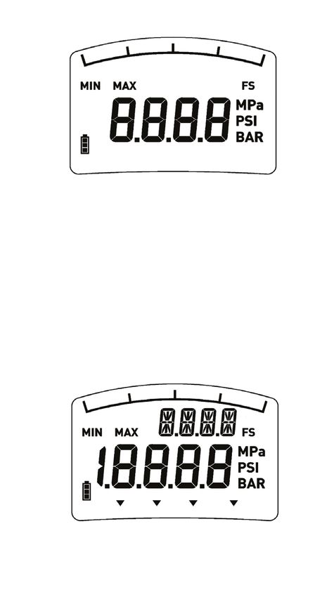
3.7 Labelling, safety marks
Product label
EN Product label for hydraulic ring force transducer with pressure gauge
Product label for hydraulic ring force transducer with pressure sensor
Model
Nominal size
Measuring range
Serial number, tag number
Date of manufacture calendar week/year
Output signal
Manufacturer/address
ADPR1X914115.01 10/2020 EN/DE
Observe the instructions stated on the product label of the pressure
measuring instrument.
10 Operating instructions, models F6137, F6148, F6160, F61714. Transport, packaging and storage
4. Transport, packaging and storage
4.1 Transport
Check the hydraulic ring force transducer for any damage that may have been caused
by transport. Obvious damage must be reported immediately. EN
CAUTION!
Damage through improper transport
With improper transport, a high level of damage to property can occur.
▶ When unloading packed goods upon delivery as well as during
internal transport, proceed carefully and observe the symbols on the
packaging.
▶ With internal transport, observe the instructions in chapter 4.2
“Packaging and storage”.
As precision measuring instruments, hydraulic ring force transducers require careful
handling during transport and mounting. Load impacts during transport (e.g. hitting
a hard surface) can lead to irreversible damage, resulting in measuring errors in the
subsequent measuring operation.
4.2 Packaging and storage
Do not remove packaging until just before mounting.
Keep the packaging as it will provide optimum protection during transport (e.g. change
in installation site, sending for repair).
The hydraulic ring force transducer has been manufactured from coated steel.
■ The design with pressure gauge fulfils IP65 ingress protection.
■ The design with digital pressure gauge fulfils IP65 ingress protection.
■ The design with pressure sensor fulfils IP67 ingress protection. The design of the
accessory cables fulfils IP67 ingress protection. The ingress protection IP67 is only
guaranteed in the plugged-in state.
During storage the protective cap must always be on the electrical connection to avoid
the ingress of moisture and dirt.
Permissible conditions at the place of storage:
■ Storage temperature: -30 ... +60 °C
ADPR1X914115.01 10/2020 EN/DE
■ Humidity: 35 ... 85 % relative humidity (non-condensing)
Avoid exposure to the following factors:
■ Mechanical vibration, mechanical shock (putting it down hard)
■ Dust, dirt, and other objects may not be deposited in such a way that they form a
force shunt with the measuring piston, since this will falsify the measurement.
Operating instructions, models F6137, F6148, F6160, F6171 115. Commissioning, operation
5. Commissioning, operation
5.1 Mounting preparation
EN ■ Before mounting the hydraulic ring force transducer, the anchor hole must be drilled,
the anchor positioned, concreted and allowed to harden. For this, a level installation
face must be ensured for the hydraulic ring force transducer.
5.2 Mounting instructions
CAUTION!
Damage to the instrument through improper installation
■ The sealed threaded connections of the hydraulic force transducer
must not be loosened.
■ When installing the hydraulic force transducer, pay attention to the
installation position and thus to the direction of loading. The hydraulic
force transducer must be mounted orthogonally to the anchor.
■ The hydraulic ring force transducer should only be loaded in the
intended position.
■ In the event that, on mounting, the pressure measuring instrument
(pressure gauge, digital pressure gauge or pressure sensor) lies
against the installation face, an anchor plate must be mounted under
the hydraulic ring force transducer.
■ Torsional and transverse forces must be avoided. Transverse loads
and lateral forces also include the corresponding components of the
measurands that are introduced slanted.
■ Torsional moments, eccentric loads and transverse loads or lateral
forces cause measuring errors and may permanently damage the
hydraulic ring force transducer.
■ During installation of the hydraulic ring force transducer, the output
signal or the display instrument (force value) must always be monitored
to avoid mechanical overload.
■ When subjected to loads in other devices, a change in the zero
signal may result in permanent damage (leakage with jamming of the
measuring piston).
An overload must be excluded at all times.
ADPR1X914115.01 10/2020 EN/DE
■
■ Do not use the hydraulic ring force transducer as a climbing aid.
12 Operating instructions, models F6137, F6148, F6160, F61715. Commissioning, operation
5.3 Mounting of the hydraulic ring force transducer
Anker
Hydraulic ring force transducer with mounted pressure measuring instrument
Spannmutter
Anker
(pressure gauge, pressure sensor)
Kraftaufnehmer
Spannmutter
Ankerplatte EN
Kraftaufnehmer
not included in delivery:
Elektrischer Anschluss
Ankerplatte
Wand
Anchor plate 1
Elektrischer Anschluss Clamping nut
Anchor Wand Concrete pad
Anchor plate 2
Positioning of anchor plate 1 on the anchor . This must lie against the concrete pad .
ADPR1X914115.01 10/2020 EN/DE
Fit the hydraulic ring force transducer onto the anchor via anchor plate 1 .
Operating instructions, models F6137, F6148, F6160, F6171 135. Commissioning, operation
EN
Positioning anchor plate 2 on the hydraulic ring force transducer (piston side) on the
anchor .
Preloading the anchor using a hydraulic press. Screwing in the clamping nut .
If necessary, fix using another method.
ADPR1X914115.01 10/2020 EN/DE
14 Operating instructions, models F6137, F6148, F6160, F61715. Commissioning, operation
5.4 Commissioning of the hydraulic ring force transducer with digital pressure
gauge
Digital pressure gauge
EN
Display
Keys
Keys Function / action
■ Switches the instrument on
■ Switches the instrument off
■ Display indicates the max. value while
the key is pressed
■ Display indicates the min. value while
the key is pressed
■ Resets the max. value to “ 0 ”
ADPR1X914115.01 10/2020 EN/DE
+
■ Resets the min. value to “ 0 ”
+
Operating instructions, models F6137, F6148, F6160, F6171 155. Commissioning, operation
Display
Bar graph display
Max. value
Min. value 2nd display
EN
Full scale
Main display Unit
Battery-charge-level
indicator LO-BAT
Special function Tare
Min./max. memory
The min./max. memory is reset to the current measured value with each measuring cycle.
■ The display of the min. value is achieved by pressing the Min key.
■ The display of the max. value is achieved by pressing the Max key.
■ The resetting of the current measured value is achieved by holding down the respec-
tive key (Min or Max) and additionally briefly pressing the Menu key.
Bar graph with drag-pointer function
The additional integrated bar graph with drag-pointer function within the display
indicates the trend of the current operating pressure directly, independently from
the digital indicator. Using the drag-pointer function, the max. memory value is also
displayed in the bar graph display in the form of a bar segment, as well as in the digital
display. On resetting the min./max. value, this bar graph is then updated to the current
measured value.
Voltage supply
The digital pressure gauge is operated with 2 AA-Mignon batteries. The status of the
batteries is shown in the display . With a low battery charge level, a blinking battery
symbol is shown on the indicator display - the batteries should then be changed as soon
as possible.
ADPR1X914115.01 10/2020 EN/DE
■ Open the battery cover of the digital pressure gauge on the rear of the instrument.
■ Replace the batteries with 2 new mignon cells.
■ Close the battery cover again.
For further information and advice see the appropriate operating
instructions DG-10.
16 Operating instructions, models F6137, F6148, F6160, F61715. Commissioning, operation
5.5 Electrical connection - Hydraulic ring force transducer with pressure sensor
To prevent interferences from coupling into the system, observe the following
information:
■ Use only shielded and low-capacitance measuring cables (for cables, see chapter 10 EN
“Accessories”).
■ Ground the cable shield.
■ In the cables of the accessories, the cable shield is connected by means of the
knurled nut, thus connecting it to the case of the pressure sensor.
■ Do not install measuring cables in parallel to 3-phase-current cables and control
cables.
■ Avoid stray fields of transformers, motors and contactors.
■ Force transducers, amplifiers and processing or display units must not be grounded
several times. Connect all instruments to the same protective conductor.
The pin assignment of the connector or of the cable can be found on the product label.
For an extension, only shielded and low-capacitance cables should be used. The
permitted maximum and minimum lengths of cable are defined in ISO 11898-2. Care
should also be taken with the shielding to ensure a high-quality connection.
For further information and advice see the appropriate operating
instructions of the mounted pressure sensor.
5.5.1 Pin assignment of the analogue output - Hydraulic ring force transducer
with mounted pressure sensor
Circular connector M12 x 1, 4-pin Output 4 ... 20 mA, 2-wire
Circular connector M12 x 1, 4-pin
Pin
UB+ 1
0V/UB- 3
S+ 1
ADPR1X914115.01 10/2020 EN/DE
S- 3
Shield Case
Operating instructions, models F6137, F6148, F6160, F6171 175. Commissioning, operation / 6. Faults
6. Faults
CAUTION!
EN Physical injuries, damage to property
If faults cannot be eliminated by means of the listed measures, the hydrau-
lic ring force transducer must be taken out of operation immediately.
▶ Contact the manufacturer.
▶ If a return is needed, please follow the instructions given in chapter 9.2
“Return”.
For contact details see chapter 1 “General information” or the back page
of the operating instructions.
6.1 Faults of the hydraulic ring force transducer with pressure gauge/digital
pressure gauge
Faults Causes Measures
No display Leaking from the hydraulic ring Visual check whether the fill
force transducer fluid has leaked (glycerine-
water mixture)
Consult the manufacturer
Deviation of the zero point Overload, load offset, Consult the manufacturer
display defective force introduction
Output signal constant Mechanical overload, Consult the manufacturer
when changing force defective force introduction
Signal span varies Electromagnetic interference Shield instrument; cable
sources in the environment; shield; remove source of
e.g. frequency converter interference
Signal span drops/too small Mechanical overload, leaking Consult the manufacturer
of the hydraulic ring force
transducer
Pointer jerks with force Stick-slip effect (internal Consult the manufacturer
increase pressure too low)
ADPR1X914115.01 10/2020 EN/DE
18 Operating instructions, models F6137, F6148, F6160, F61716. Faults
6.2 Faults of the hydraulic ring force transducer with pressure sensor
Faults Causes Measures
No output signal No or wrong supply voltage, Rectify the supply voltage
or wrong output signal current pulse EN
Cable break Check the continuity
Wrong pin assignment Check pin assignment
Deviating zero-point signal Overload, load offset, wrong Consult the manufacturer
connection
Constant output signal Mechanical overload, wrong Consult the manufacturer
when changing force pin assignment, defective force
introduction
Leaking from the hydraulic ring Visual check whether the fill
force transducer fluid has leaked (glycerine-
water mixture)
Signal span varies Electromagnetic interference Shield instrument; cable
sources in the environment; shield; remove source of
e.g. frequency converter interference
Signal span drops/too small Mechanical overload, leaking Consult the manufacturer
of the hydraulic ring force
transducer
ADPR1X914115.01 10/2020 EN/DE
Operating instructions, models F6137, F6148, F6160, F6171 197. Maintenance and cleaning
7. Maintenance and cleaning
For contact details see chapter 1 “General information” or the back page
EN of the operating instructions.
7.1 Maintenance
This instrument is maintenance-free.
Repairs must only be carried out by the manufacturer.
Only use original parts (see chapter 10 “Accessories”).
7.2 Cleaning
7.2.1 Hydraulic ring force transducer with pressure gauge/digital pressure
gauge
1. Clean the hydraulic ring force transducer with a cloth.
7.2.2 Hydraulic ring force transducer with pressure sensor
1. Prior to cleaning, disconnect the hydraulic ring force transducer from the voltage
supply and dismount it.
2. Clean the hydraulic ring force transducer with a cloth.
Electrical connections must not come into contact with moisture!
CAUTION!
Damage to the instrument
Improper cleaning may lead to damage to the instrument!
▶ Do not use any aggressive cleaning agents.
▶ Do not use any hard or pointed objects for cleaning.
7.3 Recalibration
DKD/DAkkS certificate - official certificates:
ADPR1X914115.01 10/2020 EN/DE
We recommend that the hydraulic ring force transducer be regularly recalibrated by the
manufacturer, with time intervals of approx. 24 months. The basic settings will be cor-
rected if necessary.
20 Operating instructions, models F6137, F6148, F6160, F61718. Dismounting, return and disposal
8. Dismounting, return and disposal
8.1 Dismounting
DANGER! EN
Danger to life caused by electric current
Upon contact with live parts, there is a direct danger to life.
▶ The dismounting of the instrument may only be carried out by skilled
personnel.
8.1.1 Hydraulic ring force transducer with pressure gauge/digital pressure
gauge
Remove the hydraulic ring force transducer from the mounting location.
8.1.2 Hydraulic ring force transducer with pressure sensor
Remove any loading from the hydraulic ring force transducer, disconnect it from current
and remove it from the mounting location.
8.2 Return
Strictly observe the following when shipping the instrument:
All instruments delivered to WIKA must be free from any kind of hazardous substances
(acids, bases, solutions, etc.) and must therefore be cleaned before being returned.
When returning the instrument, use the original packaging or a suitable transport
packaging.
To avoid damage:
1. Wrap the instrument in an antistatic plastic film.
2. Place the instrument, along with shock-absorbent material, in the packaging.
Place shock-absorbent material evenly on all sides of the transport packaging.
3. If possible, place a bag containing a desiccant inside the packaging.
4. Label the shipment as carriage of a highly sensitive measuring instrument.
Information on returns can be found under the heading “Service” on our
local website.
ADPR1X914115.01 10/2020 EN/DE
8.3 Disposal
Incorrect disposal can put the environment at risk.
Dispose of instrument components and packaging materials in an environmentally
compatible way and in accordance with the country-specific waste disposal regulations.
Do not dispose of with household waste. Ensure a proper disposal in
accordance with national regulations.
Operating instructions, models F6137, F6148, F6160, F6171 219. Specifications
9. Specifications
Model F6137
EN Rated force Fnom 0 ... 80 kN to 0 ... 700 kN
Nominal size NS 82
Pressure measuring instrument ■ Pressure gauge 23x.50.100
(mounted) ■ Digital pressure gauge DG-10
■ Pressure sensor (on request)
Relative linearity error dlin
Pressure gauge ≤ ±1.0 % Fnom
Pressure sensor/digital pressure gauge ≤ ±0.5 % Fnom
Temperature effect on
the characteristic value TKc 1 % Fnom /10 K
the zero signal TK0 1 % Fnom /10 K
Limit force FL 100 % Fnom
Breaking force FB > 130 % Fnom
Rated displacement snom < 0.5 mm
Rated temperature range BT, nom -30 … +60 °C
Ingress protection per IEC/EN 60529
Pressure gauge IP65
Pressure sensor/digital pressure gauge IP67
Case ■ Steel, galvanised
■ Stainless steel
Piston ■ Steel, galvanised
■ Stainless steel
Guard bracket
Pressure gauge yes
Pressure sensor/digital pressure gauge optional
Mounting type
Pressure gauge direct
Pressure sensor/digital pressure gauge direct
Option Capillary, measuring hose for “separation without
any losses”
Electrical output
Output signal 4…20 mA, 2-wire
ADPR1X914115.01 10/2020 EN/DE
Supply voltage DC 0 … 30 V for current output
Load ≤ (UB - 6 V)/0.024 A
Electrical connection Circular connector M12 x 1, 4-pin
Option Hand-held measuring instrument ViSens E3908
Fill fluid (measuring piston) Glycerine 70 %, water 30 %
Force introduction as full-faced as possible, min. 75 % of the piston
diameter
Weight in kg 8
22 Operating instructions, models F6137, F6148, F6160, F61719. Specifications
Dimensions in mm
Version with pressure gauge 23x.50.100 Version with pressure sensor
120
EN
Guard bracket
Height = 55 mm
Optional:
132 Guard bracket
NS 100 Height = 44 mm
71
215
kN Connector
Ø 33 M12 x 1
4 … 20 mA
124
103,5
Ø 161
Ø 132
KEL min. Ø112
Ø 52
5
55
19
ADPR1X914115.01 10/2020 EN/DE
The sealed threaded connections of the hydraulic ring force transducer must
not be loosened!
Operating instructions, models F6137, F6148, F6160, F6171 239. Specifications
Model F6148
Rated force Fnom 0 ... 150 kN to 0 ... 1,500 kN
Nominal size NS 146
EN Pressure measuring instrument ■ Pressure gauge 23x.50.100
(mounted) ■ Digital pressure gauge DG-10
■ Pressure sensor (on request)
Relative linearity error dlin
Pressure gauge ≤ ±1.0 % Fnom
Pressure sensor/digital pressure gauge ≤ ±0.5 % Fnom
Temperature effect on
the characteristic value TKc 1 % Fnom /10 K
the zero signal TK0 1 % Fnom /10 K
Limit force FL 100 % Fnom
Breaking force FB > 130 % Fnom
Rated displacement snom < 0.5 mm
Rated temperature range BT, nom -30 … +60 °C
Ingress protection per IEC/EN 60529
Pressure gauge IP65
Pressure sensor/digital pressure gauge IP67
Case ■ Steel, galvanised
■ Stainless steel
Piston ■ Steel, galvanised
■ Stainless steel
Guard bracket
Pressure gauge yes
Pressure sensor/digital pressure gauge optional
Mounting type
Pressure gauge direct
Pressure sensor/digital pressure gauge direct
Option Capillary, measuring hose for “separation without
any losses”
Electrical output
Output signal 4 … 20 mA, 2-wire
ADPR1X914115.01 10/2020 EN/DE
Supply voltage DC 0 … 30 V for current output
Load ≤ (UB - 6 V)/0.024 A
Electrical connection Circular connector M12 x 1, 4-pin
Option Hand-held measuring instrument ViSens E3908
Fill fluid (measuring piston) Glycerine 70 %, water 30 %
Force introduction as full-faced as possible, min. 75 % of the piston
diameter
Weight in kg 13.5
24 Operating instructions, models F6137, F6148, F6160, F61719. Specifications
Dimensions in mm
Version with pressure gauge 23x.50.100 Version with pressure sensor
120 EN
Guard bracket
Height = 55 mm
Optional: Guard
NS 100 132 bracket
Height = 44 mm
71
kN Connector
Ø 33 M12 x 1
255
4 … 20 mA
164
133,5
Ø 220
Ø 194
KEL min. Ø168
Ø 90
5
55
19
ADPR1X914115.01 10/2020 EN/DE
The sealed threaded connections of the hydraulic ring force transducer must
not be loosened!
Operating instructions, models F6137, F6148, F6160, F6171 259. Specifications
Model F6160
Rated force Fnom 0 ... 400 kN to 0 ... 3,200 kN
Nominal size NS 383
EN Pressure measuring instrument ■ Pressure gauge 23x.50.100
(mounted) ■ Digital pressure gauge DG-10
■ Pressure sensor (on request)
Relative linearity error dlin
Pressure gauge ≤ ±1.0 % Fnom
Pressure sensor/digital pressure gauge ≤ ±0.5 % Fnom
Temperature effect on
the characteristic value TKc 1 % Fnom /10 K
the zero signal TK0 1 % Fnom /10 K
Limit force FL 100 % Fnom
Breaking force FB > 130 % Fnom
Rated displacement snom < 0.5 mm
Rated temperature range BT, nom -30 … +60 °C
Ingress protection per IEC/EN 60529
Pressure gauge IP65
Pressure sensor/digital pressure gauge IP67
Case ■ Steel, galvanised
■ Stainless steel
Piston ■ Steel, galvanised
■ Stainless steel
Guard bracket
Pressure gauge yes
Pressure sensor/digital pressure gauge optional
Mounting type
Pressure gauge direct
Pressure sensor/digital pressure gauge direct
Option Capillary, measuring hose for “separation without
any losses”
Electrical output
Output signal 4 … 20 mA, 2-wire
ADPR1X914115.01 10/2020 EN/DE
Supply voltage DC 0 … 30 V for current output
Load ≤ (UB - 6 V)/0.024 A
Electrical connection Circular connector M12 x 1, 4-pin
Option Hand-held measuring instrument ViSens E3908
Fill fluid (measuring piston) Glycerine 70 %, water 30 %
Force introduction as full-faced as possible, min. 75 % of the piston
diameter
Weight in kg 36
26 Operating instructions, models F6137, F6148, F6160, F61719. Specifications
Dimensions in mm
Version with pressure gauge 23x.50.100 Version with pressure sensor
120
EN
Guard bracket
Height = 55 mm
Optional: Guard
NS 100 132 bracket
Height = 44 mm
71
kN Connector
Ø 33
316
M12 x 1
4 … 20 mA
225
186
Ø 325
Ø 294
KEL min. Ø262
Ø 165
5
75
20
ADPR1X914115.01 10/2020 EN/DE
The sealed threaded connections of the hydraulic ring force transducer must
not be loosened!
Operating instructions, models F6137, F6148, F6160, F6171 279. Specifications
Model F6171
Rated force Fnom 0 ... 800 kN to 0 ... 6,000 kN
Nominal size NS 827
EN Pressure measuring instrument ■ Pressure gauge 23x.50.100
(mounted) ■ Digital pressure gauge DG-10
■ Pressure sensor (on request)
Relative linearity error dlin
Pressure gauge ≤ ±1.0 % Fnom
Pressure sensor/digital pressure gauge ≤ ±0.5 % Fnom
Temperature effect on
the characteristic value TKc 1 % Fnom /10 K
the zero signal TK0 1 % Fnom /10 K
Limit force FL 100 % Fnom
Breaking force FB > 130 % Fnom
Rated displacement snom < 0.5 mm
Rated temperature range BT, nom -30 … +60 °C
Ingress protection per IEC/EN 60529
Pressure gauge IP65
Pressure sensor/digital pressure gauge IP67
Case ■ Steel, galvanised
■ Stainless steel
Piston ■ Steel, galvanised
■ Stainless steel
Guard bracket
Pressure gauge yes
Pressure sensor/digital pressure gauge optional
Mounting type
Pressure gauge direct
Pressure sensor/digital pressure gauge direct
Option Capillary, measuring hose for “separation without
any losses”
Electrical output
Output signal 4 … 20 mA, 2-wire
ADPR1X914115.01 10/2020 EN/DE
Supply voltage DC 0 … 30 V for current output
Load ≤ (UB - 6 V)/0.024 A
Electrical connection Circular connector M12 x 1, 4-pin
Option Hand-held measuring instrument ViSens E3908
Fill fluid (measuring piston) Glycerine 70 %, water 30 %
Force introduction as full-faced as possible, min. 75 % of the piston
diameter
Weight in kg 122
28 Operating instructions, models F6137, F6148, F6160, F61719. Specifications
Dimensions in mm
Version with pressure gauge 23x.50.100 Version with pressure sensor
120
EN
Guard bracket
Height = 55 mm
Optional: Guard
NS 100 132 bracket
Height = 44 mm
71
kN Connector
370
Ø 33 M12 x 1
4 … 20 mA
280
240
Ø 389
KEL min. Ø333
11
Ø 165
130
50
ADPR1X914115.01 10/2020 EN/DE
The sealed threaded connections of the hydraulic ring force transducer must
not be loosened!
Operating instructions, models F6137, F6148, F6160, F6171 299. Specifications / 10. Accessories
9.1 Approvals
Logo Description Country
EN EU declaration of conformity European Union
■ EMC directive
■ RoHS directive
EAC Eurasian Economic Community
■ EMC directive
10. Accessories
WIKA accessories can be found online at www.wika.com.
10.1 Cables
Cable with M12 x 1 connector Order number
L=2m L=5m L = 10 m
4-pin with cable straight EZE53X011010 EZE53X011012 EZE53X011016
angled EZE53X011011 EZE53X011013 EZE53X011017
5-pin with cable straight EZE53X011043 EZE53X011044 EZE53X011047
angled EZE53X011045 EZE53X011046 EZE53X011071
ADPR1X914115.01 10/2020 EN/DE
30 Operating instructions, models F6137, F6148, F6160, F6171Annex: EU declaration of conformity
EN
ADPR1X914115.01 10/2020 EN/DE
Operating instructions, models F6137, F6148, F6160, F6171 31EN
ADPR1X914115.01 10/2020 EN/DE
32 Operating instructions, models F6137, F6148, F6160, F6171Inhalt
Inhalt
1. Allgemeines 34
2. Aufbau und Funktion 35
2.1 Überblick . . . . . . . . . . . . . . . . . . . . . . . 35
2.2 Beschreibung . . . . . . . . . . . . . . . . . . . . . 36
2.3 Lieferumfang . . . . . . . . . . . . . . . . . . . . . . 36
3. Sicherheit 36 DE
3.1 Symbolerklärung . . . . . . . . . . . . . . . . . . . . 36
3.2 Bestimmungsgemäße Verwendung . . . . . . . . . . . . . . 37
3.3 Fehlgebrauch . . . . . . . . . . . . . . . . . . . . . 38
3.4 Verantwortung des Betreibers . . . . . . . . . . . . . . . . 38
3.5 Personalqualifikation . . . . . . . . . . . . . . . . . . . 39
3.6 Persönliche Schutzausrüstung . . . . . . . . . . . . . . . 39
3.7 Beschilderung, Sicherheitskennzeichnungen . . . . . . . . . . . 40
4. Transport, Verpackung und Lagerung 41
4.1 Transport . . . . . . . . . . . . . . . . . . . . . . . 41
4.2 Verpackung und Lagerung . . . . . . . . . . . . . . . . . 41
5. Inbetriebnahme, Betrieb 42
5.1 Montagevorbereitung . . . . . . . . . . . . . . . . . . . 42
5.2 Montagehinweise . . . . . . . . . . . . . . . . . . . . 42
5.3 Montage des hydraulischen Ringkraftaufnehmers . . . . . . . . . 43
5.4 Inbetriebnahme des hydraulischen Ringkraftaufnehmers
mit Digitalmanometer . . . . . . . . . . . . . . . . . . . 45
5.5 Elektrischer Anschluss - Hydraulischer Ringkraftaufnehmer
mit Drucksensor . . . . . . . . . . . . . . . . . . . . 47
6. Störungen 48
6.1 Störungen des hydraulischen Ringkraftaufnehmers mit Manometer/
Digitalmanometer . . . . . . . . . . . . . . . . . . . . 48
6.2 Störungen des hydraulischen Ringkraftaufnehmers mit Drucksensor . . 49
7. Wartung und Reinigung 50
7.1 Wartung . . . . . . . . . . . . . . . . . . . . . . . 50
7.2 Reinigung . . . . . . . . . . . . . . . . . . . . . . . 50
7.3 Rekalibrierung . . . . . . . . . . . . . . . . . . . . . 50
8. Demontage, Rücksendung und Entsorgung 51
ADPR1X914115.01 10/2020 EN/DE
8.1 Demontage . . . . . . . . . . . . . . . . . . . . . . 51
8.2 Rücksendung . . . . . . . . . . . . . . . . . . . . . 51
8.3 Entsorgung . . . . . . . . . . . . . . . . . . . . . . 51
9. Technische Daten 52
9.1 Zulassungen . . . . . . . . . . . . . . . . . . . . . . 60
10. Zubehör 60
10.1 Kabel . . . . . . . . . . . . . . . . . . . . . . . . 60
Anlage: EU-Konformitätserklärung 61
Betriebsanleitung, Typen F6137, F6148, F6160, F6171 331. Allgemeines
1. Allgemeines
■ Die in der Betriebsanleitung beschriebenen hydraulische Ringkraftaufnehmer werden
nach dem aktuellen Stand der Technik konstruiert und gefertigt. Alle Komponenten
unterliegen während der Fertigung strengen Qualitäts- und Umweltkriterien. Unsere
Managementsysteme sind nach ISO 9001 zertifiziert.
DE ■ Diese Betriebsanleitung gibt wichtige Hinweise zum Umgang mit dem Gerät.
Voraussetzung für sicheres Arbeiten ist die Einhaltung aller angegebenen
Sicherheitshinweise und Handlungsanweisungen.
■ Die für den Einsatzbereich des Gerätes geltenden örtlichen
Unfallverhütungsvorschriften und allgemeinen Sicherheitsbestimmungen einhalten.
■ Die Betriebsanleitung ist Produktbestandteil und muss in unmittelbarer Nähe des
Gerätes für das Fachpersonal jederzeit zugänglich aufbewahrt werden. Betriebsan-
leitung an nachfolgende Benutzer oder Besitzer des Gerätes weitergeben.
■ Das Fachpersonal muss die Betriebsanleitung vor Beginn aller Arbeiten sorgfältig
durchgelesen und verstanden haben.
■ Es gelten die allgemeinen Geschäftsbedingungen in den Verkaufsunterlagen.
■ Technische Änderungen vorbehalten.
■ Werkskalibrierungen / DKD / DAkkS-Kalibrierungen erfolgen nach internationalen
Normen.
Weitere Informationen:
- Internet-Adresse: www.wika.de
- Zugehöriges Datenblatt: FO 52.20 - F6137
FO 52.21 - F6148
FO 52.22 - F6160
FO 52.23 - F6171
- Anwendungsberater: Tel.: +49 9372 132-0
Fax: +49 9372 132-406
info@wika.de
Abkürzungen, Definitionen
2-Leiter Die zwei Anschlussleitungen dienen zur Spannungsversorgung.
Der Speisestrom ist das Messsignal.
3-Leiter Zwei Anschlussleitungen dienen zur Spannungsversorgung.
Eine Anschlussleitung dient für das Messsignal.
ADPR1X914115.01 10/2020 EN/DE
UB+ Positiver Versorgungsanschluss
UB- Negativer Versorgungsanschluss
S+ Positiver Messanschluss
S- Negativer Messanschluss
34 Betriebsanleitung, Typen F6137, F6148, F6160, F61712. Aufbau und Funktion
2. Aufbau und Funktion
2.1 Überblick
Hydraulischer Ringkraftaufnehmer bestehend aus:
Druckmessgerät (Manometer oder Drucksensor) DE
Adapter
Messkolbengehäuse
Messkolben (Krafteinleitung)
Elektrischer Anschluss
Schutzbügel
Hydraulischer Ringkraftaufnehmer Hydraulischer Ringkraftaufnehmer
mit angebautem Manometer mit angebautem Drucksensor
ADPR1X914115.01 10/2020 EN/DE
Betriebsanleitung, Typen F6137, F6148, F6160, F6171 352. Aufbau und Funktion / 3. Sicherheit
2.2 Beschreibung
Hydraulische Ringkraftaufnehmer sind für das Messen statischer und dynamischer
Druckkräfte vorgesehen. Sie bestehen aus einem hydraulischen Kraftaufnehmer und
einem angebauten Druckmessgerät (Manometer, Drucksensor).
Der Messkörper ist aus galvanisch verzinktem Stahl gefertigt. Die auf den Messkolben
DE wirkende Kraft wird entsprechend der Kolbenfläche als Druck über die druckübertragen-
de Füllflüssigkeit im Messkolben auf das Druckmessgerät übertragen.
2.3 Lieferumfang
■ Hydraulischer Ringkraftaufnehmer inkl. angebautem Druckmessgerät
■ Betriebsanleitung
3. Sicherheit
3.1 Symbolerklärung
WARNUNG!
... weist auf eine möglicherweise gefährliche Situation hin, die zum Tod
oder zu schweren Verletzungen führen kann, wenn sie nicht gemieden
wird.
VORSICHT!
... weist auf eine möglicherweise gefährliche Situation hin, die zu geringfü-
gigen oder leichten Verletzungen bzw. Sach- und Umweltschäden führen
kann, wenn sie nicht gemieden wird.
Information
... hebt nützliche Tipps und Empfehlungen sowie Informationen für einen
ADPR1X914115.01 10/2020 EN/DE
effizienten und störungsfreien Betrieb hervor.
36 Betriebsanleitung, Typen F6137, F6148, F6160, F61713. Sicherheit
3.2 Bestimmungsgemäße Verwendung
Die hydraulischen Ringkraftaufnehmer sind für statische und dynamische Druckkräfte
im Bereich der Geotechnik zur Messung von Ankerkräften ausgelegt.
Typ Nenngröße Nennkraft
DE
F6137 NG 82 0 ... 80 kN bis 0 ... 700 kN
F6148 NG 146 0 ... 150 kN bis 0 ... 1.500 kN
F6160 NG 383 0 ... 400 kN bis 0 ... 3.200 kN
F6171 NG 827 0 ... 800 kN bis 0 ... 6.000 kN
Gilt für den hydraulischen Ringkraftaufnehmer mit angebautem Drucksensor:
Das Gerät ist gemäß den Sicherheitsbestimmungen für elektronische Messgeräte
gebaut und geprüft. Jeder darüber hinausgehende Gebrauch gilt als nicht bestim-
mungsgemäß. Die einwandfreie Funktion und Betriebssicherheit der Kraftaufnehmer
kann nur bei Einhaltung der Angaben in der Betriebsanleitung garantiert werden. Bei
der Verwendung sind zusätzlich die für den jeweiligen Anwendungsfall erforderlichen
Rechts- und Sicherheitsvorschriften zu beachten (z. B. VDE 0100). Sinngemäß gilt
dies auch bei Verwendung von Zubehör. Der einwandfreie und sichere Betrieb dieser
Messeinheit setzt sachgemäßen Transport, fachgerechte Lagerung, Aufstellung und
Montage sowie sorgfältige Bedienung und Instandhaltung voraus.
Das Gerät ist ausschließlich für den hier beschriebenen bestimmungsgemäßen
Verwendungszweck konzipiert und konstruiert und darf nur dementsprechend
verwendet werden.
Die technischen Spezifikationen in dieser Betriebsanleitung sind einzuhalten.
Eine unsachgemäße Handhabung oder ein Betreiben des Gerätes außerhalb der
technischen Spezifikationen macht die sofortige Stilllegung und Überprüfung durch
einen autorisierten Servicemitarbeiter erforderlich.
ADPR1X914115.01 10/2020 EN/DE
Betriebsanleitung, Typen F6137, F6148, F6160, F6171 373. Sicherheit
Elektronische Präzisionsmessgeräte mit erforderlicher Sorgfalt behandeln (vor Nässe,
Stößen, starken Magnetfeldern, statischer Elektrizität und extremen Temperaturen
schützen, keine Gegenstände in das Gerät bzw. Öffnungen einführen). Stecker und
Buchsen vor Verschmutzung schützen.
Ansprüche jeglicher Art aufgrund von nicht bestimmungsgemäßer Verwendung sind
ausgeschlossen.
DE
3.3 Fehlgebrauch
WARNUNG!
Verletzungen durch Fehlgebrauch
Fehlgebrauch des Gerätes kann zu gefährlichen Situationen und
Verletzungen führen.
▶ Eigenmächtige Umbauten am Gerät unterlassen.
Jede über die bestimmungsgemäße Verwendung hinausgehende oder andersartige
Benutzung gilt als Fehlgebrauch.
3.4 Verantwortung des Betreibers
Das Gerät wird im gewerblichen Bereich eingesetzt. Der Betreiber unterliegt daher den
gesetzlichen Pflichten zur Arbeitssicherheit.
Die Sicherheitshinweise dieser Betriebsanleitung, sowie die für den Einsatzbereich
des Gerätes gültigen Sicherheits-, Unfallverhütungs- und Umweltschutzvorschriften
einhalten.
Der Betreiber ist verpflichtet das Typenschild lesbar zu halten.
Für ein sicheres Arbeiten am Gerät muss der Betreiber das Folgende sicherstellen:
■ dass eine entsprechende Erste-Hilfe-Ausrüstung vorhanden ist und bei Bedarf
jederzeit Hilfe zur Stelle ist.
■ dass das Elektrofachpersonal regelmäßig in allen zutreffenden Fragen von
Arbeitssicherheit, Erste Hilfe und Umweltschutz unterwiesen wird, sowie die
ADPR1X914115.01 10/2020 EN/DE
Betriebsanleitung und insbesondere die darin enthaltenen Sicherheitshinweise
kennt.
■ dass das Gerät gemäß der bestimmungsgemäßen Verwendung für den
Anwendungsfall geeignet ist.
■ dass die persönliche Schutzausrüstung verfügbar ist.
38 Betriebsanleitung, Typen F6137, F6148, F6160, F61713. Sicherheit
3.5 Personalqualifikation
WARNUNG!
Verletzungsgefahr bei unzureichender Qualifikation
Unsachgemäßer Umgang kann zu erheblichen Personen- und Sachschä-
den führen.
▶ Die in dieser Betriebsanleitung beschriebenen Tätigkeiten nur durch
DE
Fachpersonal nachfolgend beschriebener Qualifikation durchführen
lassen.
Elektrofachpersonal
Das Elektrofachpersonal ist aufgrund seiner fachlichen Ausbildung, Kenntnisse und
Erfahrungen sowie Kenntnis der landesspezifischen Vorschriften, geltenden Normen
und Richtlinien in der Lage, Arbeiten an elektrischen Anlagen auszuführen und mögli-
che Gefahren selbstständig zu erkennen und zu vermeiden. Das Elektrofachpersonal ist
speziell für das Arbeitsumfeld, in dem es tätig ist, ausgebildet und kennt die relevanten
Normen und Bestimmungen. Das Elektrofachpersonal muss die Bestimmungen der
geltenden gesetzlichen Vorschriften zur Unfallverhütung erfüllen.
3.6 Persönliche Schutzausrüstung
Anforderungen an benötigte Schutzausrüstung ergeben sich aus den
Umgebungsbedingungen am Ort der Nutzung, anderen Produkten oder der
Verknüpfung mit anderen Produkten.
Die erforderliche persönliche Schutzausrüstung muss vom Betreiber zur Verfügung
gestellt werden. Der Betreiber wird durch diese Vorschläge in keinster Weise von seinen
arbeitsrechtlichen Pflichten zur Sicherheit und dem Schutz der Gesundheit der Arbeit-
nehmer entbunden.
Die Bemessung der persönlichen Schutzausrüstung muss unter Berücksichtigung aller
Betriebsparameter des Einsatzortes erfolgen.
ADPR1X914115.01 10/2020 EN/DE
Betriebsanleitung, Typen F6137, F6148, F6160, F6171 393.7 Beschilderung, Sicherheitskennzeichnungen
Typenschild
Typenschild für hydraulischen Ringkraftaufnehmer mit Manometer
DE
Typenschild für hydraulischen Ringkraftaufnehmer mit Drucksensor
Typ
Nenngröße
Messbereich
Seriennummer, Tag-Nummer
Herstellungsdatum Kalenderwoche/Jahr
Ausgangssignal
Hersteller/Adresse
ADPR1X914115.01 10/2020 EN/DE
Hinweise auf dem Typenschild des Druckmessgerätes beachten.
40 Betriebsanleitung, Typen F6137, F6148, F6160, F61714. Transport, Verpackung und Lagerung
4. Transport, Verpackung und Lagerung
4.1 Transport
Den hydraulischen Ringkraftaufnehmer auf eventuell vorhandene Transportschäden
untersuchen. Offensichtliche Schäden unverzüglich mitteilen.
VORSICHT! DE
Beschädigungen durch unsachgemäßen Transport
Bei unsachgemäßem Transport können Sachschäden in erheblicher Höhe
entstehen.
▶ Beim Abladen der Packstücke bei Anlieferung sowie innerbetrieblichem
Transport vorsichtig vorgehen und die Symbole auf der Verpackung
beachten.
▶ Bei innerbetrieblichem Transport die Hinweise unter Kapitel 4.2
„Verpackung und Lagerung“ beachten.
Als Präzisionsmessgeräte verlangen die hydraulischen Ringkraftaufnehmer beim Trans-
port und der Montage eine sorgfältige Handhabung. Laststöße während des Transports
(z. B. Aufschlag auf harten Untergrund) können zu irreversible Schäden führen, die im
späteren Messbetrieb zu Messfehlern führen.
4.2 Verpackung und Lagerung
Verpackung erst unmittelbar vor der Montage entfernen.
Die Verpackung aufbewahren, denn diese bietet bei einem Transport einen optimalen
Schutz (z. B. wechselnder Einbauort, Reparatursendung).
Der hydraulische Ringkraftaufnehmer ist aus beschichteten Stahl gefertigt.
■ Die Ausführung mit Manometer erfüllt die Schutzart IP65.
■ Die Ausführung mit Digitalmanometer erfüllt die Schutzart IP65.
■ Die Ausführung mit Drucksensor erfüllt die Schutzart IP67. Die Ausführung der
Zubehörkabel erfüllt die Schutzart IP67. Die Schutzart IP67 wird nur im gesteckten
Zustand garantiert.
Bei der Lagerung muss sich die Schutzkappe immer auf dem elektrischen Anschluss
befinden, um das Eindringen von Feuchtigkeit und Schmutz zu vermeiden.
Zulässige Bedingungen am Lagerort:
ADPR1X914115.01 10/2020 EN/DE
■ Lagertemperatur: -30 ... +60 °C
■ Feuchtigkeit: 35 ... 85 % relative Feuchte (keine Betauung)
Folgende Einflüsse vermeiden:
■ Mechanische Vibration, mechanischer Schock (hartes Aufstellen)
■ Staub, Schmutz und sonstige Gegenstände dürfen sich nicht so ablagern, dass
sie einen Kraftnebenschluss zum Messkolben bilden, da dadurch die Messung
verfälscht wird.
Betriebsanleitung, Typen F6137, F6148, F6160, F6171 415. Inbetriebnahme, Betrieb
5. Inbetriebnahme, Betrieb
5.1 Montagevorbereitung
■ Vor der Montage des hydraulischen Ringkraftaufnehmers das Ankerloch bohren,
Anker positionieren, betonieren und aushärten lassen. Hierbei muss auf eine ebene
DE Auflagefläche für den hydraulischen Ringkraftaufnehmer geachtet werden.
5.2 Montagehinweise
VORSICHT!
Beschädigung des Gerätes durch unsachgemäße Montage
■ Dichtende Verschraubungen des hydraulischen Kraftaufnehmers
dürfen nicht gelöst werden.
■ Beim Einbau des hydraulischen Kraftaufnehmers ist auf die Einbaulage
und damit auf die Belastungsrichtung zu achten. Der hydraulische
Kraftaufnehmer muss orthogonal zum Anker montiert werden.
■ Der hydraulische Ringkraftaufnehmer darf nur in der vorgesehenen
Lagerungsart belastet werden.
■ Falls das Druckmessgerät (Manometer, Digitalmanometer oder
Drucksensor) bei der Montage auf der Auflagefläche aufliegt, ist eine
Ankerplatte unter dem hydraulischen Ringkraftaufnehmer zu montieren.
■ Torsions- und Querkräfte sind zu vermeiden. Zu den Querbelastungen
und Seitenkräften gehören auch die entsprechenden Komponenten der
eventuell schräg eingeleiteten Messgrößen.
■ Torsionsmomente, außermittige Belastungen und Querbelastungen
bzw. Seitenkräfte verursachen Messfehler und können den hydrauli-
schen Ringkraftaufnehmer bleibend schädigen.
■ Während des Einbaus des hydraulischen Ringkraftaufnehmers ist das
Ausgangssignal bzw. das Anzeigegerät (Kraftwert) stets zu überwachen,
um eine mechanische Überlastung zu vermeiden.
■ Bei Belastung in anderen Vorrichtungen kann eine Veränderung des
Nullsignals eine dauerhafte Schädigung zur Folge haben (Undichtigkeit
beim Verklemmen des Messkolbens).
■ Eine Überlastung ist zu jeder Zeit auszuschließen.
Den hydraulischen Ringkraftaufnehmer nicht als Steighilfe verwenden.
ADPR1X914115.01 10/2020 EN/DE
■
42 Betriebsanleitung, Typen F6137, F6148, F6160, F61715. Inbetriebnahme, Betrieb
5.3 Montage des hydraulischen Ringkraftaufnehmers
Anker
Hydraulischer
Spannmutter
Anker Ringkraftaufnehmer mit angebautem Druckmessgerät
(Manometer,
Spannmutter Drucksensor)
Kraftaufnehmer
Ankerplatte
Kraftaufnehmer
nicht im Lieferumfang enthalten:
Elektrischer Anschluss
Ankerplatte
DE
Wand
Ankerplatte 1
Elektrischer Anschluss Spannmutter
Anker Wand Betonriegel
Ankerplatte 2
Positionierung der Ankerplatte 1 auf dem Anker . Diese muss auf dem Betonriegel
aufliegen.
ADPR1X914115.01 10/2020 EN/DE
Aufstecken des hydraulischen Ringkraftaufnehmers auf den Anker über der
Ankerplatte 1 .
Betriebsanleitung, Typen F6137, F6148, F6160, F6171 435. Inbetriebnahme, Betrieb
DE
Positionierung der Ankerplatte 2 auf dem hydraulischen Ringkraftaufnehmer (Kolben-
seite) auf dem Anker .
Vorspannung des Ankers mittels einer hydraulischen Presse. Verschraubung der
Spannmutter . Gegebenenfalls mit einer andere Methode befestigen.
ADPR1X914115.01 10/2020 EN/DE
44 Betriebsanleitung, Typen F6137, F6148, F6160, F61715. Inbetriebnahme, Betrieb
5.4 Inbetriebnahme des hydraulischen Ringkraftaufnehmers mit Digitalmanometer
Digitalmanometer
DE
Display
Tasten
Tasten Funktion / Aktion
■ Schaltet Gerät ein
■ Schaltet Gerät aus
■ Display zeigt Max-Wert an, solange
die Taste gedrückt ist
■ Display zeigt Min-Wert an, solange
die Taste gedrückt ist
■ Setzt Max-Wert auf “ 0 “ zurück
ADPR1X914115.01 10/2020 EN/DE
+
■ Setzt Min-Wert auf “ 0 “ zurück
+
Betriebsanleitung, Typen F6137, F6148, F6160, F6171 455. Inbetriebnahme, Betrieb
Display
Bargraphanzeige
Max-Wert
Min-Wert 2. Anzeige
DE
Full scale
Hauptanzeige Einheit
Ladezustandsanzeige
Batterie LO-BAT
Sonderfunktion Tara
Min-/Max-Speicher
Der Min-/Max-Speicher wird in jedem Messzyklus mit dem aktuellen Messwert aktualisiert.
■ Die Anzeige des Min-Wertes erfolgt durch Drücken der Min-Taste.
■ Die Anzeige des Max-Wertes erfolgt durch Drücken der Max-Taste.
■ Die Rücksetzung auf den aktuellen Messwert erfolgt durch Festhalten der jeweiligen
Taste (Min oder Max) und kurzes zusätzliches Betätigen der Menu-Taste.
Bargraph mit Schleppzeigerfunktion
Die zusätzlich in der Anzeige integrierte Bargraphanzeige mit Schleppzeigerfunk-
tion zeigt direkt die Tendenz des momentanen Arbeitsdruckes unabhängig von der
Digitalanzeige an. Mit Hilfe der Schleppzeigerfunktion wird der Max-Speicherwert
zusätzlich zur Digitalanzeige auch in der Bargraphanzeige in Form eines Balkenseg-
mentes angezeigt. Dieses Balkensegment wird bei Rücksetzung des Min / Max Wertes
ebenfalls auf den aktuellen Messwert aktualisiert.
Spannungsversorgung
Das Digitalmanometer wird mit 2 Mignon Batterien AA betrieben. Der Zustand der
Batterien wird im Display angezeigt . Bei einem niedrigen Ladezustand der Batterien
erscheint ein blinkendes Batteriesymbol auf dem Anzeigedisplay, die Batterien sind
dann sobald wie möglich auszutauschen.
ADPR1X914115.01 10/2020 EN/DE
■ Den Batteriedeckel des Digitalmanometers auf der Geräterückseite öffnen.
■ Die Batterien durch 2 neue Mignon-Zellen ersetzen.
■ Den Batteriedeckel wieder schließen.
Weitere Hinweise, siehe auch Betriebsanleitung DG-10.
46 Betriebsanleitung, Typen F6137, F6148, F6160, F6171You can also read