Analogue cable amplifier, model B1940 Analoger Kabelmessverstärker, Typ B1940 - Model B1940
←
→
Page content transcription
If your browser does not render page correctly, please read the page content below

Operating instructions
                           Betriebsanleitung

Analogue cable amplifier, model B1940               EN

Analoger Kabelmessverstärker, Typ B1940             DE

                   Model B1940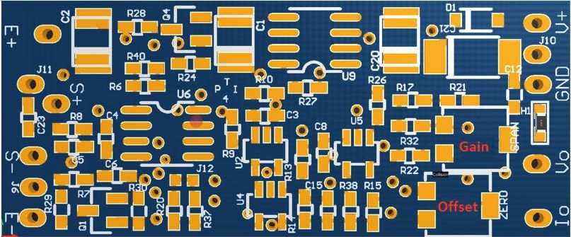
EN   Operating instructions model B1940                                      Page                3 - 22

DE   Betriebsanleitung Typ F1940                                             Seite              23 - 43

     © 07/2021 WIKA Alexander Wiegand SE & Co. KG
                                                                                                          79107154.01 07/2021 EN/DE

     All rights reserved. / Alle Rechte vorbehalten.
     WIKA® is a registered trademark in various countries.
     WIKA® ist eine geschützte Marke in verschiedenen Ländern.

     Prior to starting any work, read the operating instructions!
     Keep for later use!

     Vor Beginn aller Arbeiten Betriebsanleitung lesen!
     Zum späteren Gebrauch aufbewahren!

      2                                                             Operating instructions, model B1940
Contents

                               Contents
                               1. General information                                                                                         4
                               2. Design and function                                                                                         5
                                   2.1 Overview  .   .   .   .   .   .   .   .   .   .   .   .   .   .   .   .   .   .   .   .   .   .   . 5
                                                                                                                                                  EN
                                   2.2 Description . . . . . . . . . . . . . . . . . . . . . . . 5
                                   2.3 Scope of delivery  .  .  .  .  .  .  .  .  .  .  .  .  .  .  .  .  .  .  .  . 5
                               3. Safety                                                                                                      6
                                   3.1 Explanation of symbols  .  .  .  .  .  .  .  .  .  .  .  .  .  .  .  .  .  . 6
                                   3.2 Intended use  .  .  .  .  .  .  .  .  .  .  .  .  .  .  .  .  .  .  .  .  .  . 6
                                   3.3 Improper use  .   .   .   .   .   .   .   .   .   .   .   .   .   .   .   .   .   .   .   .   .   . 7
                                   3.4 Responsibility of the operator   .   .   .   .   .   .   .   .   .   .   .   .   .   .   .   . 7
                                   3.5 Personnel qualification  .   .   .   .   .   .   .   .   .   .   .   .   .   .   .   .   .   .   . 8
                                   3.6 Personal protective equipment  .   .   .   .   .   .   .   .   .   .   .   .   .   .   .   . 8
                                   3.7 Labelling, safety marks  .  .  .  .  .  .  .  .  .  .  .  .  .  .  .  .  .  . 9
                               4. Transport, packaging and storage                                                                           10
                                   4.1 Transport  .   .   .   .   .   .   .   .   .   .   .   .   .   .   .   .   .   .   .   .   .   .   . 10
                                   4.2 Packaging and storage  .  .  .  .  .  .  .  .  .  .  .  .  .  .  .  .  .  . 10
                               5. Commissioning, operation                                                                                   11
                                   5.1 Pin assignment  .  .  .  .  .  .  .  .  .  .  .  .  .  .  .  .  .  .  .  .  . 11
                                   5.2 Commissioning  .  .  .  .  .  .  .  .  .  .  .  .  .  .  .  .  .  .  .  .  . 12
                                   5.3 Factory setting the sensor output  .  .  .  .  .  .  .  .  .  .  .  .  .  .  . 12
                                   5.4 Factory setting the sensor sensitivity  .   .   .   .   .   .   .   .   .   .   .   .   .  12
                                   5.5 Zero point offset of the output signal  .  .  .  .  .  .  .  .  .  .  .  .  .  . 12
                                   5.6 Adjustment of the output signal span  .   .   .   .   .   .   .   .   .   .   .   .   .  13
                                   5.7 Connection for strain gauge force transducer  .  .  .  .  .  .  .  .  .  .  . 13
                                   5.8 Evaluation connection  .   .   .   .   .   .   .   .   .   .   .   .   .   .   .   .   .   .  13
                                   5.9 Mounting   .   .   .   .   .   .   .   .   .   .   .   .   .   .   .   .   .   .   .   .   .   .   . 14
                                   5.10 Avoidance of disturbances  .   .   .   .   .   .   .   .   .   .   .   .   .   .   .   .  15
                               6. Faults                                                                                                     16
                               7. Maintenance and cleaning                                                                                   17
                                   7.1 Maintenance  .  .  .  .  .  .  .  .  .  .  .  .  .  .  .  .  .  .  .  .  .  . 17
                                   7.2 Cleaning  .  .  .  .  .  .  .  .  .  .  .  .  .  .  .  .  .  .  .  .  .  .  . 17
                               8. Dismounting, return and disposal                                                                           17
                                   8.1 Dismounting  .  .  .  .  .  .  .  .  .  .  .  .  .  .  .  .  .  .  .  .  .  . 17
                                   8.2 Return  .   .   .   .   .   .   .   .   .   .   .   .   .   .   .   .   .   .   .   .   .   .   .   . 17
OI_79107154.01 07/2021 EN/DE

                                   8.3 Disposal  .  .  .  .  .  .  .  .  .  .  .  .  .  .  .  .  .  .  .  .  .  .  . 18
                               9. Specifications                                                                                             19
                                   9.1 Approvals  .  .  .  .  .  .  .  .  .  .  .  .  .  .  .  .  .  .  .  .  .  .  . 20
                               10. Accessories                                                                                               21
                               Annex: EU declaration of conformity                                                                           22

                                Operating instructions, model B1940                                                                          3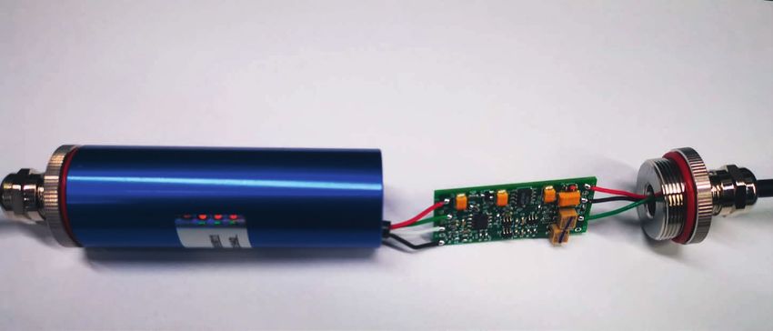
1. General information

     1. General information
     ■ The junction box described in the operating instructions has been designed and
          manufactured using state-of-the-art technology. All components are subject to strin-
EN        gent quality and environmental criteria during production. Our management systems
          are certified to ISO 9001.
     ■    These operating instructions contain important information on handling the instru-
          ment. Working safely requires that all safety instructions and work instructions are
          observed.
     ■    Observe the relevant local accident prevention regulations and general safety regula-
          tions for the instrument's range of use.
     ■    The operating instructions are part of the product and must be kept in the immediate
          vicinity of the instrument and readily accessible to skilled personnel at any time. Pass
          the operating instructions on to the next operator or owner of the instrument.
     ■    Skilled personnel must have carefully read and understood the operating instructions
          prior to beginning any work.
     ■    The general terms and conditions contained in the sales documentation shall apply.
     ■    Subject to technical modifications.

     Further information:
        - Internet address:              www.wika.de

          - Relevant data sheet:         AC 50.09

          - Application consultant:      Tel.: +49 9372 132-0
                                         Fax: +49 9372 132-406
                                         info@wika.de

     Abbreviations, definitions
     2-wire     The two connection leads are used for the voltage supply.
                The measuring signal also provides the supply current.
     4-wire     The four connection leads are used for the voltage supply.
                The measuring signal also provides the supply current.
     6-wire     The six connection leads are used for the voltage supply.
                One connection lead is used for the measuring signal.
     Exc+       Positive power supply terminal
     Exc-       Negative power supply terminal
     Sig+       Positive output terminal
                                                                                                     OI_79107154.01 07/2021 EN/DE

     Sig-       Negative output terminal
     SHLD       Shield
     x-pin      Pin assignment

      4                                                       Operating instructions, model B1940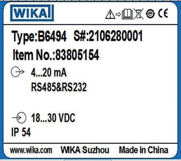
2. Design and function
2. Design and function
2.1 Overview
EN
Cable gland
Case
Cable ⇒ amplifier side
Cable ⇒ force transducer side
Reduction
2.2 Description
The B1940 analogue cable amplifier is used to adapt the output signal of strain gauge
force transducers to indicators or to a downstream controller. The case corresponds
to IP67 ingress protection and is thus suitable for use in harsh environments. All strain
gauge force transducers that can be operated with a DC voltage can be connected.
With the combination of the cable amplifier with a force transducer, this force unit can
be adjusted in line with customer wishes. The supply voltage of DC 18 ... 30 V ensures a
direct connection to a PLC. This usually features a 24-volt supply voltage. The analogue
output enables the direct signal processing in the PLC.
2.3 Scope of delivery
■ Analogue cable amplifier
OI_79107154.01 07/2021 EN/DE
■ Operating instructions
Operating instructions, model B1940 5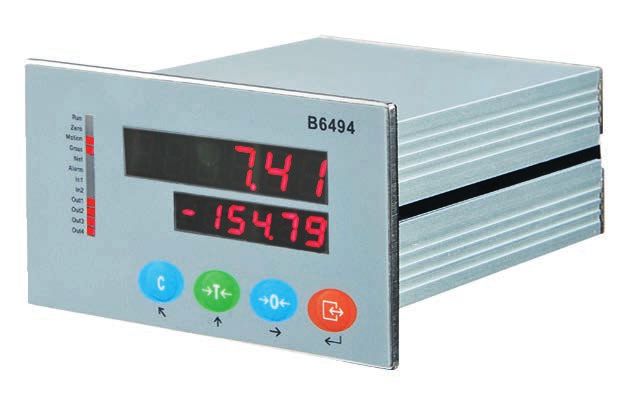
3. Safety

     3. Safety
     3.1   Explanation of symbols

EN                WARNING!
                  ... indicates a potentially dangerous situation that can result in serious
                  injury or death, if not avoided.

                  CAUTION!
                  ... indicates a potentially dangerous situation that can result in light injuries
                  or damage to property or the environment, if not avoided.

                  Information
                  ... points out useful tips, recommendations and information for efficient
                  and trouble-free operation.

     2.4   Intended use

      Models                      Version
      B1940                       Analogue cable amplifier

     The B1940 is an analogue amplifier for strain gauge force transducers.

     The instrument has been designed and built solely for the intended use described here,
     and may only be used accordingly. The technical specifications contained in these
     operating instructions must be observed. Improper handling or operation of the instru-
     ment outside of its technical specifications requires the instrument to be taken out of
     service immediately and inspected by an authorised service engineer.

     The safety and accident prevention regulations applicable in specific individual cases
     must be observed (e.g. VDE0100 and VDE0113).

     Handle electronic precision measuring instruments with the required care (protect from
                                                                                                      OI_79107154.01 07/2021 EN/DE

     humidity, impacts, strong magnetic fields, static electricity and extreme temperatures,
     do not insert any objects into the instrument or its openings). Plugs and sockets must be
     protected from contamination.

     The manufacturer shall not be liable for claims of any type based on operation contrary
     to the intended use.

      6                                                       Operating instructions, model B1940
3. Safety

                               3.2   Improper use

                                             WARNING!
                                             Injuries through improper use
                                             Improper use of the instrument can lead to hazardous situations and            EN
                                             injuries.
                                             ▶ Refrain from unauthorised modifications to the instrument.

                               Any use beyond or different to the intended use is considered as improper use.

                               3.3   Responsibility of the operator

                               The instrument is used in the industrial sector. The operator is therefore responsible for
                               legal obligations regarding safety at work.

                               The safety instructions within these operating instructions, as well as the safety,
                               accident prevention and environmental protection regulations for the application area
                               must be maintained.

                               The operator is obliged to maintain the product label in a legible condition.

                               To ensure safe working on the instrument, the operating company must ensure
                               ■ that suitable first-aid equipment is available and aid is provided whenever required.
                               ■ that the operating personnel are regularly instructed in all topics regarding work
                                  safety, first aid and environmental protection and know the operating instructions
                                  and, in particular, the safety instructions contained therein.
                               ■ that the instrument is suitable for the particular application in accordance with its
                                  intended use.
                               ■ that personal protective equipment is available.
OI_79107154.01 07/2021 EN/DE

                                Operating instructions, model B1940                                                     7
3. Safety

     3.4   Personnel qualification

                  WARNING!
                  Risk of injury should qualification be insufficient
EN                Improper handling can result in considerable injury and damage to
                  property.
                  ▶ The activities described in these operating instructions may only be
                     carried out by skilled personnel who have the qualifications described
                     below.

     Skilled electrical personnel
     Skilled electrical personnel are understood to be personnel who, based on their techni-
     cal training, know-how and experience as well as their knowledge of country-specific
     regulations, current standards and directives, are capable of carrying out work on
     electrical systems and independently recognising and avoiding potential hazards. The
     skilled electrical personnel have been specifically trained for the work environment they
     are working in and know the relevant standards and regulations. The skilled electrical
     personnel must comply with current legal accident prevention regulations.

     3.5   Personal protective equipment

     The requirements for the required protective equipment result from the ambient condi-
     tions at the place of use, other products or the connection to other products.

     The requisite personal protective equipment must be provided by the operating compa-
     ny. The operator is in no way relieved of his obligations under labour law for the safety
     and the protection of workers' health.

     The design of the personal protective equipment must take into account all operating
     parameters of the place of use.                                                              OI_79107154.01 07/2021 EN/DE

      8                                                     Operating instructions, model B1940
3. Safety
3.6 Labelling, safety marks
Product label
EN
Model
Manufacturer's logo
Serial number
Manufacturer's address
Ingress protection per DIN EN 60259
Output signal
Supply voltage
Product code
Before mounting and commissioning the instrument, ensure you read the
operating instructions!
OI_79107154.01 07/2021 EN/DE
Do not dispose of with household waste. Ensure a proper disposal in
accordance with national regulations.
Operating instructions, model B1940 94. Transport, packaging and storage
4. Transport, packaging and storage
4.1 Transport
Check the cable amplifier for any damage that may have been caused by transport.
EN Obvious damage must be reported immediately.
CAUTION!
Damage through improper transport
With improper transport, a high level of damage to property can occur.
▶ When unloading packed goods upon delivery as well as during internal
transport, proceed carefully and observe the symbols on the packag-
ing.
▶ With internal transport, observe the instructions in chapter 4.2
“Packaging and storage”.
If the instrument is transported from a cold into a warm environment, the formation of
condensation may result in instrument malfunction. Before putting it back into operation,
wait for the instrument temperature and the room temperature to equalise.
4.2 Packaging and storage
Do not remove packaging until just before mounting.
Keep the packaging as it will provide optimum protection during transport (e.g. change
in installation site, sending for repair).
Permissible conditions at the place of storage:
■ Storage temperature: -30 ... +80 °C
Avoid exposure to the following factors:
■ Mechanical vibration, mechanical shock (putting it down hard)
■ Direct sunlight
■ Dust and contamination
■ Ambient temperature too high
■ Humidity, condensation, rain, snow, etc.
OI_79107154.01 07/2021 EN/DE
10 Operating instructions, model B19405. Commissioning, operation
5. Commissioning, operation
5.1 Pin assignment
Sensor side Amplifier side
EN
Exc+ DC 18 ... 30 V
Sig+ 0V
Voltage output
DC 0 ... ±10 V /
Sig-
DC 0 … ±5 V
Current output
Exc- 0 ... 20 mA/
4 ... 20 mA
Resistor R6 Potentiometer
Pin assignment of the force transducer Signal
Exc+ Excitation voltage +
Sig+ Output signal +
Sig- Output signal -
Exc- Excitation voltage -
The standard shielded cable is not connected to the analogue cable amplifier B1940; it
can be connected to excitation voltage on customer request.
Output signal Connection name
Supply voltage+ V+ DC 18 ... 30 V
Supply voltage- GND DC 0 V
Current output Io 0 … 20 mA / 4 … 20 mA
Voltage output Vo DC 0 … ±10 V / DC 0 … ±5 V
Potentiometer Sensor output
OI_79107154.01 07/2021 EN/DE
Offset Zero point offset
Gain Range adjustment
CAUTION!
If the connection between sensor and B1940 is changed, the adjustment
and thus the calibration is invalid.
Operating instructions, model B1940 115. Commissioning, operation
5.2 Commissioning
The instrument is switched on and ready for operation as soon as it is connected to the
power supply.
EN
5.3 Factory setting the sensor output
Output: ±10 V
The output voltage can be adjusted by ±5 V by switching the gain potentiometer. By
adjusting the gain potentiometer screw anticlockwise, the signal can be lowered to ±5 V.
Output: 4 ... 20 mA
The current output can be set to 0 ... 20 mA using the offset potentiometer. By adjusting
the offset potentiometer screw anticlockwise, the signal can be lowered to 0 mA.
Information
Only one signal output variant can be set!
5.4 Factory setting the sensor sensitivity
The B1940 is factory-set to approx. 2 mV/V. If the sensitivity of the sensor deviates
from this value, the resistor R6 on the PCB must be replaced. First the sensitivity of the
sensor must be determined by referring to the data sheet, test certificate, sensor label,
etc. Then this value is to be multiplied by 210 and the correct resistor is to be selected to
replace the standard resistor.
Example 1: 0.7 mV/V * 210 Ω = 147 Ω
Example 2: 1.0 mV/V * 210 Ω = 210 Ω
Example 3: 2.0 mV/V * 210 Ω = 420 Ω
Information
Only a resistor with an accuracy of 1 % or better and a temperature coeffi-
cient of 50 ppm or better may be used.
The size of the resistor is 0603.
OI_79107154.01 07/2021 EN/DE
5.5 Zero point offset of the output signal
The zero point of the output signal can be adjusted with the offset potentiometer on the
PCB. Turning the potentiometer screw clockwise adjusts the zero point upwards, turning
it anticlockwise adjusts it downwards.
12 Operating instructions, model B19405. Commissioning, operation
5.6 Adjustment of the output signal span
The output signal span can be adjusted with the gain potentiometer on the PCB. Turning
the potentiometer screw clockwise adjusts the span upwards, turning it anticlockwise
adjusts it downwards. EN
5.7 Connection for strain gauge force transducer
Strain gauge force trans- Properties
ducer
Supply via B1940 10.00 V max. 20 mA, short-circuit-proof
Bridge resistance min. 350 ohm, full bridge only, 4- or 6-wire
Sensitivity up to 0.35 mV/V ... 3 mV/V, other values on request
5.8 Evaluation connection
Output signal Properties
Voltage output DC ±10 V or ±5 V max. 5 mA output resistance < 1 ohm
Current output 0 ... 20 mA, 4 ... 20 mA, impedance max. 400 ohm
Information
Only one signal output variant can be set!
CAUTION!
The instrument must be disconnected from the mains during any connec-
tion procedures. Follow the safety instructions.
OI_79107154.01 07/2021 EN/DE
Operating instructions, model B1940 135. Commissioning, operation
5.9 Mounting
EN Sensor side Amplifier side
Reduction Reduction
Unscrewing the case of the analogue cable amplifier
■ Assignment of the amplifier side and the sensor side. Refer to data sheet if necessary.
■ Loosen the cable gland on the sensor side.
■ Rotate the blue case part on the amplifier side without twisting the cable on the
sensor side at the same time.
■ Then carefully pull the case over the cable on the sensor side.
Screwing the case of the analogue cable amplifier
■ Slide the blue case part with the reduction screwed onto the sensor side, but with the
screw open, over the PCB and carefully pull on the sensor cable.
■ Screw the blue case part with the reduction on the amplifier side without simultane-
ously twisting the sensor cable as the blue case part rotates.
■ Tighten the screw connection.
CAUTION!
Damage to the instrument through improper installation
■ If the sequence of mounting and dismounting is not observed, the
instruments may be damaged as a result.
Observe the sequence!
OI_79107154.01 07/2021 EN/DE
14 Operating instructions, model B19405. Commissioning, operation
5.10 Avoidance of disturbances
To prevent interferences from coupling into the system, observe the following
information:
■ The instrument must not be connected directly to the mains. The specifications of the EN
supply voltage must be observed.
■ Do not connect any voltage to unassigned pins.
■ The instrument must not be exposed to electromagnetic transients higher than those
specified by the standard.
■ Disconnect the cable directly at the connector, do not pull on the cable.
■ During mounting and installation, care must be taken to ensure consistent spatial separa-
tion between lines associated with interference (e.g. high-power circuits) and the measu-
ring and control lines.
■ The distance to all other control and high-power lines must be at least 0.5 m.
■ Avoid stray fields of transformers, motors and contactors.
■ Use only shielded and low-capacitance measuring cables.
■ The pin assignment of the load cell can be found on the product label or in the operating
instructions of the load cell.
■ The junction box must be grounded.
■ Ground the shield of the read-out unit.
■ Transducers, amplifiers and processing or read-out units must not be grounded several
times. All instruments must be connected to the same protective conductor.
The pin assignment of the connector or of the cable can be found on the product label.
When using extensions, only shielded and low-capacitance cables should be used. The
permitted maximum and minimum lengths of cable are defined in ISO 11898-2. Care should
be taken also to ensure a high-quality connection of the shield.
Information
All parts connected to the application must generally be shielded and
wired properly.
CAUTION!
Damage to the instrument through improper installation
■ If the connection between the force transducer and B1940 is changed,
the adjustment and thus the calibration is invalid.
OI_79107154.01 07/2021 EN/DE
Operating instructions, model B1940 155. Commissioning, operation
Amplifier output, flying lead, unassembled
PE
EN
UB brown DC +24 V
Strain gauge S+ yellow Power supply unit
amplifier 0V green GND
-
Evaluation
+ Display
6. Faults
CAUTION!
Physical injuries, damage to property
If faults cannot be eliminated by means of the measures listed, the
junction box must be taken out of operation immediately.
▶ Contact the manufacturer.
▶ If a return is needed, please follow the instructions given in chapter 8.2
“Return”.
For contact details, please see chapter 1 “General information” or the back
page of the operating instructions.
Faults Causes Measures
No output signal No or wrong supply voltage, Correct the supply voltage
current pulse
Cable break Check the continuity
No or wrong output signal Incorrect adjustment Repeat adjustment
Deviating zero point signal Incorrect adjustment Repeat adjustment
Constant output signal when Output signal of the sensor is Use another sensor
OI_79107154.01 07/2021 EN/DE
changing force not suitable
Signal span varies EMC interference sources Shield instrument; cable
in the environment, e.g., shielding; remove source of
frequency converter interference
Signal span drops/too small Mechanical overloading Consult the manufacturer
16 Operating instructions, model B19407. Maintenance and cleaning / 8. Dismounting, return ...
7. Maintenance and cleaning
For contact details, please see chapter 1 “General information” or the back
page of the operating instructions. EN
7.1 Maintenance
This instrument is maintenance-free.
Repairs must only be carried out by the manufacturer.
Only use original parts (see chapter 10 “Accessories”).
7.2 Cleaning
1. Prior to cleaning, disconnect the junction box from the voltage supply and dismount
it.
2. Clean the junction box with a cloth.
Electrical connections must not come into contact with moisture!
CAUTION!
Damage to the instrument
Improper cleaning may lead to damage to the instrument!
▶ Do not use any aggressive cleaning agents.
▶ Do not use any hard or pointed objects for cleaning.
8. Dismounting, return and disposal
8.1 Dismounting
DANGER!
Danger to life caused by electric current
Upon contact with live parts, there is a direct danger to life.
▶ The dismounting of the instrument may only be carried out by skilled
personnel.
Disconnect the cable amplifier from power and the force transducers.
OI_79107154.01 07/2021 EN/DE
8.2 Return
Strictly observe the following when shipping the instrument:
All instruments delivered to WIKA must be free from any kind of hazardous substances
(acids, bases, solutions, etc.) and must therefore be cleaned before being returned.
When returning the instrument, use the original packaging or a suitable transport
packaging.
Operating instructions, model B1940 178. Dismounting, return and disposal
To avoid damage:
1. Wrap the instrument in an antistatic plastic film.
2. Place the instrument, along with shock-absorbent material, in the packaging.
Place shock-absorbent material evenly on all sides of the transport packaging.
EN 3. If possible, place a bag containing a desiccant inside the packaging.
4. Label the shipment as carriage of a highly sensitive measuring instrument.
Information on returns can be found under the heading “Service” on our
local website.
8.3 Disposal
Incorrect disposal can put the environment at risk.
Dispose of instrument components and packaging materials in an environmentally
compatible way and in accordance with the country-specific waste disposal regulations.
Do not dispose of with household waste. Ensure a proper disposal in
accordance with national regulations.
OI_79107154.01 07/2021 EN/DE
18 Operating instructions, model B19409. Specifications
9. Specifications
Model B1940 Version 0/4 ... 20 mA Version DC 0 ... 10 V
Input signal 4 x 350 Ω sensor, 4- or 6-wire
EN
Sensitivity 0.35 ... 3 mV/V
Linearity < 0.01 % FS
Output signal 0/4 ... 20 mA, 3-wire DC ±5 V / ±10 V, 3-wire
Residual ripple < 10 mV at 400 Ω < 10 mV
Max. loading Load < 400 Ω -
Output resistance -Dimensions in mm
EN
Ø25
90
115
9.1 Approvals
Logo Description Country
EU declaration of conformity European Union
■ RoHS directive
OI_79107154.01 07/2021 EN/DE
20 Operating instructions, model B194010. Accessories
10. Accessories
WIKA accessories can be found online at www.wika.com.
Model Description
EN
F4801 Load cell
F4801 single point load cells are particularly suitable for use in
platforms. They can be mounted directly under platforms without
any additional design engineering and adjustment effort.
■ Measuring ranges 0 ... 3 kg to 0 ... 250 kg
■ Load cell made from aluminium
■ High accuracy
■ Insensitive to lateral and corner load
■ Ingress protection IP65
B6494 Digital display
The B6494 digital display is well suited for numerous applications
because of their accuracy and being easy to read. The connec-
tion to the corresponding force transducer and the parameteri-
sation are usually performed by the customer for this model.
Programming the instrument is menu-driven. All strain gauge
force transducers can be connected.
■ Dual mV/V display
■ 2 x digital input and 4 x digital output
■ Integrated multiple signal outputs available
■ Serial interface, RS-232 or RS-485
■ Ingress protection IP65
B6578 Junction box
The junction box B6578 is intended for the parallel connection
of up to 4 force transducers or load cells in industrial weighing
technology.
■ 4-channel
■ Rugged stainless steel case
■ Cable connection via clamps
■ Ingress protection IP67
OI_79107154.01 07/2021 EN/DE
Operating instructions, model B1940 21Annex: EU declaration of conformity
EN
OI_79107154.01 07/2021 EN/DE
22 Operating instructions, model B1940Inhalt
Inhalt
1. Allgemeines 4
2. Aufbau und Funktion 5
2.1 Übersicht . . . . . . . . . . . . . . . . . . . . . . . 5
2.2 Beschreibung . . . . . . . . . . . . . . . . . . . . . . 5
2.3 Lieferumfang . . . . . . . . . . . . . . . . . . . . . . 5
3. Sicherheit 6
DE
3.1 Symbolerklärung . . . . . . . . . . . . . . . . . . . . . 6
3.2 Bestimmungsgemäße Verwendung . . . . . . . . . . . . . . 6
3.3 Fehlgebrauch . . . . . . . . . . . . . . . . . . . . . . 7
3.4 Verantwortung des Betreibers . . . . . . . . . . . . . . . . 7
3.5 Personalqualifikation . . . . . . . . . . . . . . . . . . . 8
3.6 Persönliche Schutzausrüstung . . . . . . . . . . . . . . . . 8
3.7 Beschilderung, Sicherheitskennzeichnungen . . . . . . . . . . . 9
4. Transport, Verpackung und Lagerung 10
4.1 Transport . . . . . . . . . . . . . . . . . . . . . . . 10
4.2 Verpackung und Lagerung . . . . . . . . . . . . . . . . . 10
5. Inbetriebnahme, Betrieb 11
5.1 Anschlussbelegung . . . . . . . . . . . . . . . . . . . 11
5.2 Inbetriebnahme . . . . . . . . . . . . . . . . . . . . . 12
5.3 Werkseinstellung des Sensorausgangs . . . . . . . . . . . . 12
5.4 Werkseinstellung der Sensorempfindlichkeit . . . . . . . . . . . 12
5.5 Nullpunkt-Offset des Ausgangssignals . . . . . . . . . . . . . 12
5.6 Anpassung der Ausgangssignalspanne . . . . . . . . . . . . 13
5.7 Anschluss für DMS-Kraftaufnehmer . . . . . . . . . . . . . . 13
5.8 Auswertungsverbindung . . . . . . . . . . . . . . . . . . 13
5.9 Montage . . . . . . . . . . . . . . . . . . . . . . . 14
5.10 Vermeidung von Störungen . . . . . . . . . . . . . . . . 15
6. Störungen 16
7. Wartung und Reinigung 17
7.1 Wartung . . . . . . . . . . . . . . . . . . . . . . . 17
7.2 Reinigung . . . . . . . . . . . . . . . . . . . . . . . 17
8. Demontage, Rücksendung und Entsorgung 17
8.1 Demontage . . . . . . . . . . . . . . . . . . . . . . 17
8.2 Rücksendung . . . . . . . . . . . . . . . . . . . . . 17
OI_79107154.01 07/2021 EN/DE
8.3 Entsorgung . . . . . . . . . . . . . . . . . . . . . . 18
9. Technische Daten 19
9.1 Zulassungen . . . . . . . . . . . . . . . . . . . . . . 20
10. Zubehör 21
Anlage: EU-Konformitätserklärung 22
Betriebsanleitung, Typ B1940 231. Allgemeines
1. Allgemeines
■ Der in der Betriebsanleitung beschriebene Anschlusskasten wird nach dem aktuellen
Stand der Technik konstruiert und gefertigt. Alle Komponenten unterliegen während
der Fertigung strengen Qualitäts- und Umweltkriterien. Unsere Managementsysteme
sind nach ISO 9001 zertifiziert.
■ Diese Betriebsanleitung gibt wichtige Hinweise zum Umgang mit dem Gerät.
DE
Voraussetzung für sicheres Arbeiten ist die Einhaltung aller angegebenen
Sicherheitshinweise und Handlungsanweisungen.
■ Die für den Einsatzbereich des Gerätes geltenden örtlichen
Unfallverhütungsvorschriften und allgemeinen Sicherheitsbestimmungen einhalten.
■ Die Betriebsanleitung ist Produktbestandteil und muss in unmittelbarer Nähe des
Gerätes für das Fachpersonal jederzeit zugänglich aufbewahrt werden. Betriebsan-
leitung an nachfolgende Benutzer oder Besitzer des Gerätes weitergeben.
■ Das Fachpersonal muss die Betriebsanleitung vor Beginn aller Arbeiten sorgfältig
durchgelesen und verstanden haben.
■ Es gelten die allgemeinen Geschäftsbedingungen in den Verkaufsunterlagen.
■ Technische Änderungen vorbehalten.
Weitere Informationen:
- Internet-Adresse: www.wika.de
- Zugehöriges Datenblatt: AC 50.09
- Anwendungsberater: Tel.: +49 9372 132-0
Fax: +49 9372 132-406
info@wika.de
Abkürzungen, Definitionen
2-Leiter Die zwei Anschlussleitungen dienen zur Spannungsversorgung.
Der Speisestrom ist das Messsignal.
4-Leiter Die vier Anschlussleitungen dienen zur Spannungsversorgung.
Der Speisestrom ist das Messsignal.
6-Leiter Die sechs Anschlussleitungen dienen zur Spannungsversorgung.
Eine Anschlussleitung dient für das Messsignal.
Exc+ Positiver Versorgungsanschluss
Exc- Negativer Versorgungsanschluss
Sig+ Positiver Messanschluss
OI_79107154.01 07/2021 EN/DE
Sig- Negativer Messanschluss
SHLD Schirm
x-polig Anschlussbelegung
24 Betriebsanleitung, Typ B19402. Aufbau und Funktion
2. Aufbau und Funktion
2.1 Übersicht
DE
Kabelverschraubung
Gehäuse
Kabel ⇒ Verstärkerseite
Kabel ⇒ Kraftaufnehmerseite
Reduzierung
2.2 Beschreibung
Der analoge Kabelmessverstärker B1940 dient der Anpassung des Ausgangssignals
von DMS-Kraftaufnehmern an Informatoren oder an die nachgeschaltete Steuerung.
Das Gehäuse entspricht der Schutzart IP67 und ist somit auch für den Einsatz in rauer
Umgebung geeignet. Anschließbar sind alle DMS-Kraftaufnehmer, die mit einer Gleich-
spannung betrieben werden können. Bei der Kombination des Kabelmessverstärkers
mit einem Kraftaufnehmer wird diese Krafteinheit nach Kundenwunsch justiert. Die
Hilfsenergie von DC 18 ... 30 V gewährleistet einen direkten Anschluss an eine SPS.
Diese weist meist eine 24-Volt-Hilfsenergie auf. Der Analogausgang erlaubt die direkte
Signalverarbeitung in der SPS.
2.3 Lieferumfang
OI_79107154.01 07/2021 EN/DE
■ Analoger Kabelmessverstärker
■ Betriebsanleitung
Betriebsanleitung, Typ B1940 253. Sicherheit
3. Sicherheit
3.1 Symbolerklärung
WARNUNG!
... weist auf eine möglicherweise gefährliche Situation hin, die zum Tod
oder zu schweren Verletzungen führen kann, wenn sie nicht gemieden
DE wird.
VORSICHT!
... weist auf eine möglicherweise gefährliche Situation hin, die zu geringfü-
gigen oder leichten Verletzungen bzw. Sach- und Umweltschäden führen
kann, wenn sie nicht gemieden wird.
Information
... hebt nützliche Tipps und Empfehlungen sowie Informationen für einen
effizienten und störungsfreien Betrieb hervor.
2.4 Bestimmungsgemäße Verwendung
Typen Ausführung
B1940 Analoger Kabelmessverstärker
Der B1940 ist ein analoger Verstärker für DMS-Kraftaufnehmer.
Das Gerät ist ausschließlich für den hier beschriebenen bestimmungsgemäßen
Verwendungszweck konzipiert und konstruiert und darf nur dementsprechend verwen-
det werden. Die technischen Spezifikationen in dieser Betriebsanleitung sind einzuhal-
ten. Eine unsachgemäße Handhabung oder ein Betreiben des Gerätes außerhalb der
technischen Spezifikationen macht die sofortige Stilllegung und Überprüfung durch
einen autorisierten Servicemitarbeiter erforderlich.
Die im speziellen Einzelfall geltenden Sicherheits- und Unfallverhütungsvorschriften
sind zu beachten (z.B. VDE0100 und VDE0113).
OI_79107154.01 07/2021 EN/DE
Elektronische Präzisionsmessgeräte mit erforderlicher Sorgfalt behandeln (vor Nässe,
Stößen, starken Magnetfeldern, statischer Elektrizität und extremen Temperaturen
schützen, keine Gegenstände in das Gerät bzw. Öffnungen einführen). Stecker und
Buchsen vor Verschmutzung schützen.
Ansprüche jeglicher Art aufgrund von nicht bestimmungsgemäßer Verwendung sind
ausgeschlossen.
26 Betriebsanleitung, Typ B19403. Sicherheit
3.2 Fehlgebrauch
WARNUNG!
Verletzungen durch Fehlgebrauch
Fehlgebrauch des Gerätes kann zu gefährlichen Situationen und
Verletzungen führen.
▶ Eigenmächtige Umbauten am Gerät unterlassen.
DE
Jede über die bestimmungsgemäße Verwendung hinausgehende oder andersartige
Benutzung gilt als Fehlgebrauch.
3.3 Verantwortung des Betreibers
Das Gerät wird im gewerblichen Bereich eingesetzt. Der Betreiber unterliegt daher den
gesetzlichen Pflichten zur Arbeitssicherheit.
Die Sicherheitshinweise dieser Betriebsanleitung, sowie die für den Einsatzbereich des
Gerätes gültigen Sicherheits-, Unfallverhütungs- und Umweltschutzvorschriften einhal-
ten.
Der Betreiber ist verpflichtet, das Typenschild lesbar zu halten.
Für ein sicheres Arbeiten am Gerät muss der Betreiber sicherstellen,
■ dass eine entsprechende Erste-Hilfe-Ausrüstung vorhanden ist und bei Bedarf jeder-
zeit Hilfe zur Stelle ist.
■ dass das Bedienpersonal regelmäßig in allen zutreffenden Fragen von Arbeitssicher-
heit, Erste Hilfe und Umweltschutz unterwiesen wird, sowie die Betriebsanleitung
und insbesondere die darin enthaltenen Sicherheitshinweise kennt.
■ dass das Gerät gemäß der bestimmungsgemäßen Verwendung für den
Anwendungsfall geeignet ist.
■ dass die persönliche Schutzausrüstung verfügbar ist.
OI_79107154.01 07/2021 EN/DE
Betriebsanleitung, Typ B1940 273. Sicherheit
3.4 Personalqualifikation
WARNUNG!
Verletzungsgefahr bei unzureichender Qualifikation
Unsachgemäßer Umgang kann zu erheblichen Personen- und Sachschä-
den führen.
▶ Die in dieser Betriebsanleitung beschriebenen Tätigkeiten nur durch
DE Fachpersonal nachfolgend beschriebener Qualifikation durchführen
lassen.
Elektrofachpersonal
Das Elektrofachpersonal ist aufgrund seiner fachlichen Ausbildung, Kenntnisse und
Erfahrungen sowie Kenntnis der landesspezifischen Vorschriften, geltenden Normen
und Richtlinien in der Lage, Arbeiten an elektrischen Anlagen auszuführen und mögli-
che Gefahren selbstständig zu erkennen und zu vermeiden. Das Elektrofachpersonal ist
speziell für das Arbeitsumfeld, in dem es tätig ist, ausgebildet und kennt die relevanten
Normen und Bestimmungen. Das Elektrofachpersonal muss die Bestimmungen der
geltenden gesetzlichen Vorschriften zur Unfallverhütung erfüllen.
3.5 Persönliche Schutzausrüstung
Anforderungen an benötigte Schutzausrüstung ergeben sich sich aus den
Umgebungsbedingungen am Ort der Nutzung, anderen Produkten oder der
Verknüpfung mit anderen Produkten.
Die erforderliche persönliche Schutzausrüstung muss vom Betreiber zur Verfügung
gestellt werden. Der Betreiber wird durch diese Vorschläge in keinster Weise von seinen
arbeitsrechtlichen Pflichten zur Sicherheit und dem Schutz der Gesundheit der Arbeit-
nehmer entbunden.
Die Bemessung der persönlichen Schutzausrüstung muss unter Berücksichtigung aller
Betriebsparameter des Einsatzortes erfolgen.
OI_79107154.01 07/2021 EN/DE
28 Betriebsanleitung, Typ B19403. Sicherheit
3.6 Beschilderung, Sicherheitskennzeichnungen
Typenschild
DE
Typ
Herstellerlogo
Seriennummer
Herstelleradresse
Schutzart gem. DIN EN 60259
Ausgangssignal
Hilfsenergie
Produktcode
Vor Montage und Inbetriebnahme des Gerätes unbedingt die Betriebsan-
leitung lesen!
OI_79107154.01 07/2021 EN/DE
Nicht mit dem Hausmüll entsorgen. Für eine geordnete Entsorgung
gemäß nationaler Vorgaben sorgen.
Betriebsanleitung, Typ B1940 294. Transport, Verpackung und Lagerung
4. Transport, Verpackung und Lagerung
4.1 Transport
Den Kabelmessverstärker auf eventuell vorhandene Transportschäden untersuchen.
Offensichtliche Schäden unverzüglich mitteilen.
DE VORSICHT!
Beschädigungen durch unsachgemäßen Transport
Bei unsachgemäßem Transport können Sachschäden in erheblicher Höhe
entstehen.
▶ Beim Abladen der Packstücke bei Anlieferung sowie innerbetrieblichem
Transport vorsichtig vorgehen und die Symbole auf der Verpackung
beachten.
▶ Bei innerbetrieblichem Transport die Hinweise unter Kapitel 4.2
„Verpackung und Lagerung“ beachten.
Wird das Gerät von einer kalten in eine warme Umgebung transportiert, so kann durch
Kondensatbildung eine Störung der Gerätefunktion eintreten. Vor einer erneuten
Inbetriebnahme die Angleichung der Gerätetemperatur an die Raumtemperatur
abwarten.
4.2 Verpackung und Lagerung
Verpackung erst unmittelbar vor der Montage entfernen.
Die Verpackung aufbewahren, denn diese bietet bei einem Transport einen optimalen
Schutz (z. B. wechselnder Einbauort, Reparatursendung).
Zulässige Bedingungen am Lagerort:
■ Lagertemperatur: -30 ... +80 °C
Folgende Einflüsse vermeiden:
■ Mechanische Vibration, mechanischer Schock (hartes Aufstellen)
■ Direkte Sonneneinstrahlung
■ Staub und Verschmutzung
■ Zu hohe Umgebungstemperatur
■ Feuchtigkeit, Kondenswasser, Regen, Schnee usw.
OI_79107154.01 07/2021 EN/DE
30 Betriebsanleitung, Typ B19405. Inbetriebnahme, Betrieb
5. Inbetriebnahme, Betrieb
5.1 Anschlussbelegung
Sensorseite Verstärkerseite
Exc+ DC 18 ... 30 V
DE
Sig+ 0V
Spannungs-
ausgang
Sig-
DC 0 ... ±10 V /
DC 0 … ±5 V
Exc- Stromaus-
gang
0 ... 20 mA /
Widerstand R6 Potentiometer
4 ... 20 mA
Anschlussbelegung Signal
Kraftaufnehmer
Exc+ Speisespannung +
Sig+ Ausgangssignal +
Sig- Ausgangssignal -
Exc- Speisespannung -
Das standardmäßig abgeschirmte Kabel ist nicht an den analogen Kabelmessverstärker
B1940 angeschlossen, kann auf Kundenwunsch an Speisespannung- angeschlossen
werden.
Ausgangssignal Anschlussname
Hilfsenergie+ V+ DC 18 ... 30 V
Hilfsenergie- GND DC 0 V
Stromausgang Io 0 … 20 mA / 4 … 20 mA
Spannungsausgang Vo DC 0 … ±10 V / DC 0 … ±5 V
Potentiometer Sensorausgang
OI_79107154.01 07/2021 EN/DE
Offset Nullpunkt-Offset
Gain Spannweitenabgleich
VORSICHT!
Wird die Verbindung zwischen Sensor und B1940 geändert, ist der
Abgleich und damit die Kalibrierung ungültig.
Betriebsanleitung, Typ B1940 315. Inbetriebnahme, Betrieb
5.2 Inbetriebnahme
Das Gerät ist eingeschaltet und betriebsbereit, sobald es an die Stromversorgung
angeschlossen wird.
5.3 Werkseinstellung des Sensorausgangs
DE
Ausgang: ±10 V
Die Ausgangsspannung kann durch Umschalten des Gain-Potentiometers ±5 V einge-
stellt werden. Durch Einstellen der Gain-Potentiometer-Schraube gegen den Uhrzeiger-
sinn kann das Signal auf ±5 V gesenkt werden.
Ausgang: 4 ... 20 mA
Der Stromausgang kann durch Umschalten des Offset-Potentiometers auf 0 ... 20 mA
eingestellt werden. Durch Einstellen der Offset-Potentiometer-Schraube gegen den
Uhrzeigersinn kann das Signal auf 0 mA gesenkt werden.
Information
Es kann nur eine Signalausgangsvariante eingestellt werden!
5.4 Werkseinstellung der Sensorempfindlichkeit
Werkseitig ist der B1940 auf ca. 2 mV/V eingestellt. Weicht die Empfindlichkeit des
Sensors von diesem Wert ab, muss der Widerstand R6 auf der Leiterplatte ersetzt
werden. Zuerst muss die Empfindlichkeit des Sensors anhand von Datenblatt, Prüfzer-
tifikat, Sensoretikett usw. bestimmt werden. Anschließend diesen Wert mit 210 multi-
plizieren und den richtigen Widerstand auswählen, um den Standardwiderstand zu
ersetzen.
Beispiel 1: 0,7 mV/V * 210 Ω = 147 Ω
Beispiel 2: 1,0 mV/V * 210 Ω = 210 Ω
Beispiel 3: 2,0 mV/V * 210 Ω = 420 Ω
Information
Es darf nur ein Widerstand mit einer Genauigkeit von 1 % oder besser
und ein Temperaturkoeffizient von 50 ppm oder besser verwendet werden.
OI_79107154.01 07/2021 EN/DE
Die Baugröße des Widerstandes ist 0603.
5.5 Nullpunkt-Offset des Ausgangssignals
Der Nullpunkt des Ausgangssignals kann mit dem Offset-Potentiometer auf der Leiter-
platte eingestellt werden. Durch Drehen der Potentiometerschraube im Uhrzeigersinn
wird der Nullpunkt nach oben verstellt, gegen den Uhrzeigersinn wird er nach unten
verstellt.
32 Betriebsanleitung, Typ B19405. Inbetriebnahme, Betrieb
5.6 Anpassung der Ausgangssignalspanne
Die Ausgangssignalspanne kann mit dem Gain-Potentiometer auf der Leiterplatte
eingestellt werden. Durch Einstellen der Potentiometerschraube im Uhrzeigersinn wird
die Spanne nach oben und gegen den Uhrzeigersinn nach unten gedreht.
5.7 Anschluss für DMS-Kraftaufnehmer
DE
DMS-Kraftaufnehmer Eigenschaften
Versorgung über B1940 10,00 V max. 20 mA, kurzschlussfest
Brückenwiderstand min. 350 Ohm, nur Vollbrücke, 4- oder 6-Leiter
Empfindlichkeit bis 0,35 mV/V ... 3 mV/V, andere Werte auf Anfrage
5.8 Auswertungsverbindung
Ausgangssignal Eigenschaften
Spannungsausgang DC ±10 V oder ±5 V max. 5 mA Ausgangswiderstand < 1 Ohm
Stromausgang 0 ... 20 mA, 4 ... 20 mA, Impedanz max. 400 Ohm
Information
Es kann nur eine Signalausgangsvariante eingestellt werden!
VORSICHT!
Das Gerät muss bei allen Anschlussvorgängen vom Netz getrennt sein.
Sicherheitshinweise beachten.
OI_79107154.01 07/2021 EN/DE
Betriebsanleitung, Typ B1940 335. Inbetriebnahme, Betrieb
5.9 Montage
Sensorseite Verstärkerseite
Reduzierung Reduzierung
DE
Aufschrauben des Gehäuses des analogen Kabelmessverstärkers
■ Zuordnung der Verstärkerseite und der Sensorseite. Ggf. das Datenblatt prüfen.
■ Kabelverschraubung auf der Sensorseite lösen.
■ Das blaue Gehäuseteil auf der Verstärkerseite drehen ohne gleichzeitig das Kabel
auf der Sensorseite zu drehen.
■ Ziehen Sie dann das Gehäuse auf der Sensorseite vorsichtig über das Kabel.
Verschrauben des Gehäuses des analogen Kabelmessverstärkers
■ Schieben Sie das blaue Gehäuseteil mit der sensorseitig verschraubten Reduzie-
rung, aber offener Schraube, über die Leiterplatte und ziehen Sie vorsichtig am
Sensorkabel.
■ Verschrauben Sie das blaue Gehäuseteil mit der Reduzierung auf der Verstärkersei-
te, ohne gleichzeitig das Sensorkabel mit dem blauen Gehäuseteil zu drehen.
■ Schraubverbindung festziehen.
VORSICHT!
Beschädigung des Gerätes durch unsachgemäße Montage
■ Wird die Reihenfolge der Montage und -Demontage nicht eingehalten,
so können die Geräte dadurch beschädigt werden.
Bitte Reihenfolge beachten!
OI_79107154.01 07/2021 EN/DE
34 Betriebsanleitung, Typ B19405. Inbetriebnahme, Betrieb
5.10 Vermeidung von Störungen
Um Einkopplungen von Störungen zu vermeiden folgende Hinweise beachten:
■ Das Gerät darf nicht direkt an das Stromnetz angeschlossen werden. Die Angaben der
Hilfsenergie sind zu beachten.
■ Keine Spannung an unbelegten Pins anschließen.
■ Das Gerät darf keinem höheren elektromagnetischen Transienten ausgesetzt werden, als
von der Norm festgelegt.
DE
■ Kabel direkt am Stecker trennen, nicht am Kabel ziehen.
■ Bei der Montage und Installation ist auf eine konsequente räumliche Trennung zwischen
störbehafteten Leitungen (z. B. Starkstromkreisen) und den Mess- und Steuerleitungen
zu achten.
■ Der Abstand zu allen anderen Steuer- und Starkstromleitungen muss mindestens 0,5 m
betragen.
■ Streufelder von Transformatoren sowie Motoren und Schützen vermeiden.
■ Nur abgeschirmte, kapazitätsarme Messkabel verwenden.
■ Die Anschlussbelegung der Wägezelle sind dem Typenschild bzw. der Betriebsanleitung
der Wägezelle zu entnehmen.
■ Der Anschlusskasten ist zu erden.
■ Schirm des Auswerteeinheit erden.
■ Aufnehmer, Verstärker und Verarbeitungs- bzw. Auswerteeinheit dürfen nicht mehrfach
geerdet werden. Alle Geräte sind an den selben Schutzleiter anzuschließen.
Die Anschlussbelegung des Steckers oder des Kabels sind dem Typenschild zu entnehmen.
Beim Verlängern dürfen nur abgeschirmte und kapazitätsarme Kabel verwendet werden. Die
erlaubten maximalen und minimalen Längen des Kabels sind in der ISO 11898-2 angege-
ben. Dabei ist auf eine hochwertige Verbindung auch der Abschirmung zu achten.
Information
Grundsätzlich sind alle an die Applikation angeschlossenen Teile in die
Schirmung mit einzubeziehen und ordnungsgemäß zu verkabeln.
VORSICHT!
Beschädigung des Gerätes durch unsachgemäße Montage
■ Wird die Verbindung zwischen dem Kraftaufnehmer und B1940
geändert, ist der Abgleich und damit die Kalibrierung ungültig.
OI_79107154.01 07/2021 EN/DE
Betriebsanleitung, Typ B1940 355. Inbetriebnahme, Betrieb
Verstärkerausgang, freies Kabelende, unkonfektioniert
PE
UB braun DC +24 V
DE DMS-Messverstärker
S+ gelb Netzteil
0V grün GND
-
Auswertung
+ Anzeige
6. Störungen
VORSICHT!
Körperverletzungen, Sachschäden
Können Störungen mit Hilfe der aufgeführten Maßnahmen nicht beseitigt
werden, den Anschlusskasten unverzüglich außer Betrieb setzen.
▶ Kontakt mit dem Hersteller aufnehmen.
▶ Bei notwendiger Rücksendung die Hinweise unter Kapitel 8.2
„Rücksendung“ beachten.
Kontaktdaten siehe Kapitel 1 „Allgemeines“ oder Rückseite der Betriebs-
anleitung.
Störungen Ursachen Maßnahmen
Kein Ausgangssignal Keine oder falsche Hilfsenergie korrigieren
Hilfsenergie, Stromstoß
Kabelbruch Durchgang überprüfen
Kein oder falsches Falsche Justage Justage erneut durchführen
Ausgangssignal
Abweichendes Falsche Justage Justage erneut durchführen
OI_79107154.01 07/2021 EN/DE
Nullpunkt-Signal
Gleichbleiben des Ausgangs- Ausgangssignal des Sensors Anderen Sensor verwenden
signals bei Kraftänderung ist nicht geeignet
Signalspanne schwankend EMV-Störquellen in Gerät abschirmen; Leitungs-
Umgebung, z. B. Frequenz- abschirmung; Störquelle
umrichter entfernen
Signalspanne fällt ab/zu klein Mechanische Überlastung Rücksprache mit Hersteller
36 Betriebsanleitung, Typ B19407. Wartung und Reinigung / 8. Demontage, Rücksendung..
7. Wartung und Reinigung
Kontaktdaten siehe Kapitel 1 „Allgemeines“ oder Rückseite der Betriebs-
anleitung.
DE
7.1 Wartung
Dieses Gerät ist wartungsfrei.
Reparaturen sind ausschließlich vom Hersteller durchzuführen.
Nur Originalteile verwenden (siehe Kapitel 10 „Zubehör”).
7.2 Reinigung
1. Vor der Reinigung den Anschlusskasten ordnungsgemäß von der
Spannungsversorgung trennen und ausbauen.
2. Den Anschlusskasten mit einem Tuch reinigen.
Elektrische Anschlüsse nicht mit Feuchtigkeit in Berührung bringen!
VORSICHT!
Beschädigung des Gerätes
Eine unsachgemäße Reinigung führt zur Beschädigung des Gerätes!
▶ Keine aggressiven Reinigungsmittel verwenden.
▶ Keine harten und spitzen Gegenstände zur Reinigung verwenden.
8. Demontage, Rücksendung und Entsorgung
8.1 Demontage
GEFAHR!
Lebensgefahr durch elektrischen Strom
Bei Berührung mit spannungsführenden Teilen besteht unmittelbare
Lebensgefahr.
▶ Die Demontage des Gerätes darf nur durch Fachpersonal erfolgen.
Den Kabelmessverstärker von Strom und den Kraftaufnehmern trennen.
OI_79107154.01 07/2021 EN/DE
8.2 Rücksendung
Beim Versand des Gerätes unbedingt beachten:
Alle an WIKA gelieferten Geräte müssen frei von Gefahrstoffen (Säuren, Laugen,
Lösungen, etc.) sein und sind daher vor der Rücksendung zu reinigen.
Zur Rücksendung des Gerätes die Originalverpackung oder eine geeignete
Transportverpackung verwenden.
Betriebsanleitung, Typ B1940 378. Demontage, Rücksendung und Entsorgung
Um Schäden zu vermeiden:
1. Das Gerät in eine antistatische Plastikfolie einhüllen.
2. Das Gerät mit dem Dämmmaterial in der Verpackung platzieren.
Zu allen Seiten der Transportverpackung gleichmäßig dämmen.
3. Wenn möglich einen Beutel mit Trocknungsmittel der Verpackung beifügen.
4. Sendung als Transport eines hochempfindlichen Messgerätes kennzeichnen.
DE
Hinweise zur Rücksendung befinden sich in der Rubrik „Service“ auf
unserer lokalen Internetseite.
8.3 Entsorgung
Durch falsche Entsorgung können Gefahren für die Umwelt entstehen.
Gerätekomponenten und Verpackungsmaterialien entsprechend den
landesspezifischen Abfallbehandlungs- und Entsorgungsvorschriften umweltgerecht
entsorgen.
Nicht mit dem Hausmüll entsorgen. Für eine geordnete Entsorgung
gemäß nationaler Vorgaben sorgen.
OI_79107154.01 07/2021 EN/DE
38 Betriebsanleitung, Typ B19409. Technische Daten
9. Technische Daten
Typ B1940 Ausführung 0/4 ... 20 mA Ausführung DC 0 ... 10 V
Eingangssignal 4 x 350 Ω Sensor, 4- oder 6-Leiter
Empfindlichkeit 0,35 ... 3 mV/V
Linearität < 0,01 % FS
DE
Ausgangssignal 0/4 ... 20 mA, 3-Leiter DC ±5 V / ±10 V, 3-Leiter
Restwelligkeit < 10 mV bei 400 Ω < 10 mV
Max. Belastung Bürde < 400 Ω -
Ausgangswiderstand -Abmessungen in mm
DE
Ø25
90
115
9.1 Zulassungen
Logo Beschreibung Land
EU-Konformitätserklärung Europäische Union
■ RoHS-Richtlinie
OI_79107154.01 07/2021 EN/DE
40 Betriebsanleitung, Typ B194010. Zubehör
10. Zubehör
WIKA-Zubehör finden Sie online unter www.wika.de.
Typ Beschreibung
F4801 Wägezelle
DE
Plattformwägezellen F4801 sind besonders für den Einsatz in
Plattformen geeignet. Ohne zusätzlichen Konstruktions- und
Abgleichaufwand können sie direkt unter Plattformen montiert
werden.
■ Messbereiche 0 … 3 kg bis 0 ... 250 kg
■ Wägezelle aus Aluminium
■ Hohe Genauigkeit
■ Unempfindlich gegenüber Seiten- und Eckenlast
■ Schutzart IP65
B6494 Digitalanzeige
Die Digitalanzeige B6494 eignen sich durch ihre Genauigkeit und
gute Lesebarkeit für zahlreiche Anwendungen. Der Anschluss
an den entsprechenden Kraftaufnehmer und die Parametrierung
erfolgen bei diesem Typ in der Regel durch den Kunden. Die
Programmierung des Gerätes wird menügeführt durchgeführt.
Anschließbar sind alle DMS-Kraftaufnehmer.
■ 2-fache mV/V Anzeige
■ 2 x Digitaleingang und 4 x Digitalausgang
■ Integrierte Mehrfach-Signalausgänge verfügbar
■ Serielle Schnittstelle, RS-232 oder RS-485
■ Schutzart IP65
B6578 Anschlusskasten
Der Anschlusskasten B6578 ist für den parallelen Anschluss von
bis zu 4 Kraftaufnehmern oder Wägezellen in der industriellen
Wägetechnik vorgesehen.
■ 4-kanalig
■ Stabiles Gehäuse in CrNi-Stahl
■ Kabelanschluss über Klemmen
■ Schutzart IP67
OI_79107154.01 07/2021 EN/DE
Betriebsanleitung, Typ B1940 41Anlage: EU-Konformitätserklärung
DE
OI_79107154.01 07/2021 EN/DE
42 Betriebsanleitung, Typ B1940DE
OI_79107154.01 07/2021 EN/DE
Betriebsanleitung, Typ B1940 43WIKA subsidiaries worldwide can be found online at www.wika.com.
WIKA-Niederlassungen weltweit finden Sie online unter www.wika.de.
WIKA Alexander Wiegand SE & Co. KG
79107154.01 07/2021 EN/DE
Alexander-Wiegand-Straße 30
63911 Klingenberg • Germany
Tel. +49 9372 132-0
Fax +49 9372 132-406
info@wika.de
www.wika.de
44 Operating instructions, model B1940You can also read