DP1 User manual Benutzerhandbuch Manuel de l'utilisateur Användarhandbok - ENGLISH DEUTSCH FRANÇAIS SVENSKA - Interspiro
←
→
Page content transcription
If your browser does not render page correctly, please read the page content below
ENGLISH
                                                 DEUTSCH
                                                FRANÇAIS
                                                 SVENSKA

                                                    DP1
User manual • Benutzerhandbuch • Manuel de l'utilisateur •
                                    Användarhandbok

                                                   96708L91
                                                    2021-03
Copyright © 2021 Interspiro This publication contains or refers to proprietary information which is protected by copyright. All rights are reserved. Interspiro®, Oxydive® and Divator® are registered trademarks belonging to Interspiro. This publication may not be copied, photocopied, reproduced, translated, or converted to any electronic or machinereadable form in whole or in part, without prior written approval from Interspiro.
DP1 • DP1 • DP1 • DP1

Table of Contents
DP1 .......................................................................................................... 7
    Safety notice ..................................................................................... 7
            Safety terminology and symbols ................................................. 7
            Safety notice ............................................................................. 8
    Before use ...................................................................................... 10
            Technical description ................................................................ 10
            Preparation ............................................................................. 11
    During use ...................................................................................... 14
            Operating procedures .............................................................. 14
            Extreme conditions .................................................................. 14
            Emergency procedures ............................................................ 14
    After use ......................................................................................... 16
            Disconnection .......................................................................... 16
            Cleaning ................................................................................. 16
            Visual inspection ...................................................................... 17
            Full hose inspection ................................................................. 18
            Anti-freezing unit ...................................................................... 19
            Winding the supply hose .......................................................... 22
            Leakage test ........................................................................... 24
            Service and testing .................................................................. 25
            Transport and storage .............................................................. 25
DP1 ........................................................................................................ 27
    Sicherheitshinweis ........................................................................... 27
            Sicherheitsbegriffe und -symbole .............................................. 27
            Sicherheitshinweis ................................................................... 28
    Vor dem Einsatz .............................................................................. 30
            Technische Beschreibung ......................................................... 30
            Vorbereitung ............................................................................ 31
    Während des Tauchgangs ................................................................ 35
            Arbeitsanweisungen ................................................................. 35
            Extreme Bedingungen .............................................................. 35
            Notfallmaßnahmen .................................................................. 35
    Nach Gebrauch ............................................................................... 37
            Abschaltung ............................................................................ 37
            Reinigung ................................................................................ 37
            Sichtprüfung ............................................................................ 38
            Vollständige Schlauchprüfung ................................................... 39
            Frostschutzgerät ...................................................................... 40
            Aufwickeln des Versorgungsschlauchs ...................................... 43

                                                                                                              3
DP1 • DP1 • DP1 • DP1
Dichtigkeitsprüfung .................................................................. 45
Service und Prüfung ................................................................ 46
Transport und Lagerung ........................................................... 47
DP1 ........................................................................................................ 49
Notice de sécurité ............................................................................ 49
Symboles et termes de sécurité ................................................ 49
Notice de sécurité .................................................................... 50
Avant utilisation ............................................................................... 52
Description technique ............................................................... 52
Préparation ............................................................................. 53
Pendant l’utilisation .......................................................................... 57
Procédures opérationnelles ...................................................... 57
Conditions extrêmes ................................................................ 57
Procédures d’urgence .............................................................. 57
Après utilisation ............................................................................... 59
Débranchement ....................................................................... 59
Nettoyage ............................................................................... 59
Inspection visuelle ................................................................... 60
Inspection complète des tuyaux ................................................ 61
Unité antigel ............................................................................ 62
Enroulement du tuyau d’alimentation ........................................ 65
Test d’étanchéité ...................................................................... 67
Entretiens et tests .................................................................... 68
Transport et stockage .............................................................. 69
DP1 ........................................................................................................ 71
Säkerhetsföreskrifter ........................................................................ 71
Säkerhetstermer och symboler ................................................. 71
Säkerhetsföreskrifter ................................................................ 72
Före användning .............................................................................. 74
Teknisk beskrivning .................................................................. 74
Förberedelse ........................................................................... 75
Användning ..................................................................................... 78
Anvisningar ............................................................................. 78
Extrema förhållanden ............................................................... 78
Rutiner för nödfall .................................................................... 78
Efter användning ............................................................................. 80
Frånkoppling ........................................................................... 80
Rengöring ............................................................................... 80
Visuell inspektion ..................................................................... 81
Fullständig slangkontroll ........................................................... 82
Frysskyddsenhet ..................................................................... 83
4DP1 • DP1 • DP1 • DP1
Linda upp ytförsörjningsslangen ................................................ 86
Läckageprovning ..................................................................... 88
Underhåll och provning ............................................................ 89
Transport och förvaring ............................................................ 89
5DP1
Safety notice
This product, supplying breathing gas to the user, has been tested in
accordance with EN 15333-1, and is to be used according local regulations.
It is approved with a supply hose up to 120 meters long and for a maximum
depth of 50 meters.
ENGLISH
Manufacturer: Interspiro AB Box 2853, 18728 Täby, Sweden
Safety terminology and symbols
In this document, the terms WARNING and NOTICE are used to indicate
potential hazards. Read the accompanying information carefully and follow the
safety instructions.
WARNING
The WARNING type of hazard statement signifies that there is
a risk of serious injury or death.
NOTICE
The NOTICE type of hazard statement signifies that there may
be a risk of damage to equipment or property.
7DP1
Safety notice
WARNING
Before using the Divator system, the user must have received
full training in its use, have read and understood these
operating instructions and demonstrated proficiency to a
responsible trainer or supervisor. Failure to do so may result in
injury or death for the user and can have serious
consequences for people to be rescued and/or items of value
to be saved.
WARNING
All users of the Divator system must be certified by a
nationally or internationally recognized scuba certification
agency. Furthermore, all users of the Divator system must be
adequately trained in its use by a certified SCUBA instructor
with knowledge and experience in the use of the Divator diving
system.
WARNING
All users of the Divator system must periodically undergo
training in emergency procedures in shallow water to maintain
preparedness in the event of an actual emergency.
8DP1
WARNING
High pressure gas systems must be handled with care.
Damage to high pressure gas system components may result
in injury or death. Interspiro is not liable for damages incurred
as a consequence of failure to follow the instructions in this
manual.
ENGLISH
WARNING
Before using the Divator system, the user must ensure that the
system has been properly inspected and maintained.
WARNING
The breathing air shall meet the requirements for breathing air
according to EN 12021.
9DP1
Before use
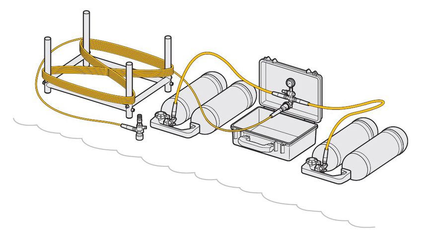
Technical description
DIVATOR DP1 is a surface supply diving system with an operating pressure of
up to 75 bar or up to 300 bar, depending on version. The pressure in the supply
hose varies between 300–55 bar or between 75-55 bar. It has two high-
pressure supply cylinder connections, each one connected to a high pressure
cylinder supply. A shuttle valve automatically switches to the supply with the
highest pressure and the supply pressure is shown on the pressure gauge.
When the supply pressure drops to 55 bar, the warning whistle sounds and the
supply must be changed by opening the second supply.
1
2 8
6
9
7 4
3
5 5 10
Surface unit
1. Pressure gauge
2. Low air whistle
3. Adapter hose
4. Vent valve
5. Connection to supply cylinder
6. Automatic shuttle valve
7. Hose connection / Hose connection w regulator (depending on version).
8. "OPEN" tag
10DP1
9. Vent handle
10. Belt
6
3
5 2
7
ENGLISH
1
3
4
Diving hose
1. Relieving loop surface
2. Relieving loop diver
3. Bend protector
4. P+ regulator with quick coupling to diver
5. Supply hose
6. Connection to outlet on surface unit
7. Carabiner
Preparation
Diver
Prepare the Divator SCUBA according to the instructions in the user manual.
Surface attendant operating procedures
A check list can be found on the inside lid of the Surface Unit.
Please note that the text on the check list may vary depending on language
region or user requirements.
1. Open the surface unit box. Place the box in such a position so that the
pressure gauge is easy to observe.
11DP1
2. Check that the supply hose is correctly wound from the last dive (see
section "Winding the supply hose").
3. Visually inspect the O-ring seals on the adapter hose cylinder connectors
and on the surface unit connection to the supply hose. If they show signs
of damage or they are missing, replace with new ones.
4. Connect the supply hose to the surface unit.
5. Secure the supply hose in a safe way to a fixed object using the eyelets.
6. Connect one adapter hose to a full supply cylinder.
7. Connect the second adapter hose to a second full supply cylinder.
8. Close the vent valves on the adaptor hoses.
9. Open one cylinder valve. Check that the audible alarm sounds, and that
the alarm stops after a short period when the pressure increases above 55
bar. Mark the open cylinder valve with the Open tag.
10. Check that the pressure in the cylinder as shown on the gauge is sufficient
to start your diving operation.
11. Connect the vent handle to the P+ regulator and flush the hose with fresh
air.
12. Check that the cylinder valve on the Divator SCUBA cylinder is completely
open (hand wheel fully opened and then turned back a ¼ of a turn).
13. Check that the supply hose is secured and correctly fastened to the divers
belt using the relieving loop and carabiner.
14. Check that the DP1 is pressurized.
15. Connect the quick coupling on the P+ regulator to the Divator SCUBA and
secure it.
NOTICE
With the lifeline correctly connected, it is possible to pull the
supply hose in any direction without straining the connection.
All the strain must be absorbed by the relieving loop and
carabiner.
12DP1
ENGLISH
WARNING
If the supply hose is connected to the diver and dived without
being pressurized the water pressure may become higher than
the air pressure on the inside of the hose and may partially fill
the inside of the hose with water. If the surface attendant then
realizes his fault and pressurizes the hose, water could be
supplied to the diver instead of air.
WARNING
If the supply hose ever enters the water not pressurized there
is the possibility of water entering the hose.
WARNING
A pressurized supply hose is not to be connected to a diver
under water.
13DP1
During use
Operating procedures
1. Frequently check the pressure on the surface unit gauge.
2. Frequently check that the supply hose does not kink.
3. Be ready to switch to the second air supply cylinder before the surface unit
pressure gauge reaches 55 bar.
4. If necessary, plan for connection of further air supply cylinders.
Switching supply cylinder
1. Open the cylinder that has full pressure.
2. Check that the pressure is rising on the pressure gauge and that the
whistle stops sounding.
3. Close the cylinder with low pressure and depressurize it through the
venting valve.
4. Move the "OPEN" sign to the open cylinder.
5. Replace the empty cylinder with a cylinder that has full pressure.
Extreme conditions
Diving in extreme conditions, such as diving in cold environments, requires
special training, planning and preparation.
Refer to the separate instruction with document number 34228, available on
the download section of interspiro.com, for more information.
Emergency procedures
Low air supply pressure, surface
• In an emergency the surface supply can be used until the air supply
pressure has dropped to approximately 20 bar .
14DP1
WARNING
The supply hose should never be re-pressurized during the
dive if the pressure in the hose has been lower than 10 bar
(145 psi). Water may enter into the hose when depressurized
and submerged.
ENGLISH
Surface supply failure, diver
• If the diver has insufficient or no surface air supply, immediately change to
bail out supply.
After activating the reserve valve function, abort dive! Start ascending
towards the water surface.
15DP1
After use
Disconnection
1. Disconnect the DP1 supply hose from the Divator SCUBA while it is
pressurized.
2. Close the DP1 cylinder valve on the DP1 supply cylinder.
3. Vent the supply hose by using the vent handle (not through the venting
valves on the adapter hoses).
WARNING
Always use hearing protection when discharging high
pressure air.
4. Protect all couplings with dust covers or park them in their parking
connections.
Cleaning
1. Clean the hose, belt and carbine hook with a cleaning solution consisting
of 10 % soap and fresh water.
2. A degreasing agent can be used to clean badly polluted parts. Before
using such agent contact the manufacturer of it to check if it is suitable in
combination with the type of materials used in Divator DP1 Surface
Supply. Follow the instructions received from the manufacturer.
3. Mechanical parts must be carefully cleaned so that sand or dust are
removed from the moving parts.
NOTICE
Remember to keep the surface supply pressurized when
washing in soap and water.
16DP1
Visual inspection
1. Inspect the eyelets at both ends of the supply hose to ensure that there is
no damage or chemical deterioration .
2. Check the quick coupling, make sure that the locking sleeve is easily
operated and that it is free from sand and dust .
3. Inspect all hoses.
If there is any suspicion of chemical or mechanical damages (such as
overload) follow the instructions in chapter "Full hose inspection".
ENGLISH
17DP1
Full hose inspection
1. Make sure that there are no chemical or mechanical damages (such as
overload) on the hose.
Inspect along the whole length of the hose that there are no:
• cuts
• scratches
• kinks or traces of kinking
• or chemical damages.
2. Make sure that the metal tubes in the ends of the hose are undamaged
and without cracks and/or rust.
3. Replace damaged hoses.
18DP1
Anti-freezing unit
Version RS4 P+
1. Check that the anti-freezing diaphragm is undamaged.
2. Check that the knob in the center is undamaged and in place.
ENGLISH
3. Check that the rubber ring on the P+ regulator relief valve does not have
any deformations.
Version MKII P+
1. Use the screwdriver.
Remove the hose clamp.
19DP1
2. Remove the anti freezing cover.
Remove the anti freezing cap.
3. Make sure that no water has entered the regulator.
If there is water in the regulator, blow compressed air into one of the holes
until the regulator is completely dry inside.
4. Lubricate the anti-freezing cap on the inside edge.
20DP1
5. Make sure to assemble it evenly along the edge.
Make sure that the cap is filled with air.
ENGLISH
6. Assemble the anti freezing cover.
Make sure that the plastic halves do not pinch the anti freezing cap.
7. Assemble the hose clamp and the cover in the direction shown in the
image.
21DP1
8. Assemble the hose clamp.
Tighten the hose clamp until the cover is locked but still possible to turn
without the anti freezing cap turning together with it.
Winding the supply hose
To avoid kinking of the supply hose it is important to wind the hose in such way
that it is free from twisting (kinks). Kinks can result in flow restrictions. The
supply hose should be wound up pressurized in a figures of eight with a
diameter greater than 500 mm (1.5 feet) for each turn. Alternatively, the hose
can be wound in a ring, but then it must be turned in the upper and lower turns
when it is wound.
When the supply hose has been wound and the pressure in the hose has been
released, it should be secured to hold it in place during handling and transport.
The ends of the supply hose must always be protected from water and dirt by
connecting the ends of the supply hose to the supplied vent handle.
22DP1
> 500 mm
ENGLISH
Divator hose winding frame
The winding frame consists of four poles to wind the supply hose around in the
figures of eight. Wind according to images depending on how long the hose is.
If the hose is 60 m or less wind it according to image 1, if it is longer, wind it
accoring to image 2. For more detailed instructions see document 96878.
1. 2.
≤ 60 m
> 60 m
23DP1
Holdall
There are also a bag with two poles that can be used to wind a supply hose
that is up to 60 m long. Wind the hose in the figure 8 around the poles in the
bag.
Leakage test
If the unit fails the leakage test it must be repaired before use.
Preparation
1. Prepare two gas cylinders filled to the same pressure, above 200 bar.
2. Connect the supply hose to the surface unit.
3. Connect the adapter hoses to the cylinders.
Test
A B
24DP1
1. Pressurize the unit by opening both cylinder valves, wait for 3 minutes to
let the pressure stabilize.
2. Tap on the pressure gauge.
3. Close both cylinder valves and check that there is no visible pressure drop
during 30 seconds.
4. At side A:
1. Open the vent valve and wait a few seconds to release the pressure in
the adapter hose.
2. Check that there is no audible leak at the cylinder connection.
3. Close the vent valve and open the cylinder valve.
ENGLISH
5. At side B:
1. Open the vent valve and wait a few seconds to release the pressure in
the adapter hose.
2. Check that there is no audible leak at the cylinder connection.
3. Close the vent valve.
Service and testing
Service and testing must as a minimum be carried out according to Interspiro’s
Service and Testing Schedule with document number 30500, or according to
local requirements.
The latest versions is found under Downloads at interspiro.com.
Transport and storage
All parts should be stored in dry conditions, well protected from direct sunlight
and extreme temperatures. During transport, the equipment must be stored so
that the equipment cannot be damaged and people cannot be injured.
The equipment must not be stored where the temperature may be expected to
go above 70 ºC (158 °F). The equipment must be completely dry before being
put into storage.
25DP1
Sicherheitshinweis
Dieses Produkt, das dem Benutzer Atemgas zuführt, wurde gemäß EN
15333-1 getestet und ist gemäß den örtlichen Vorschriften zu verwenden.
Es ist mit einem bis zu 120 Meter langen Versorgungsschlauch und bis zu
einer maximalen Tiefe von 50 Metern zugelassen.
Hersteller: Interspiro AB, Postfach 2853, 18728 Täby, Schweden
Sicherheitsbegriffe und -symbole
In diesem Dokument werden die Begriffe WARNUNG und HINWEIS
verwendet, um auf mögliche Gefahren hinzuweisen. Bitte lesen Sie die
zugehörigen Informationen sorgfältig und befolgen Sie die
Sicherheitsanweisungen.
DEUTSCH
WARNUNG
Der Warnhinweis bezeichnet als WARNUNG weist darauf hin,
dass die Gefahr schwerer oder tödlicher Verletzungen besteht.
HINWEIS
Der Gefahrenhinweis bezeichnet als HINWEIS weist auf das
Risiko hin, dass die Ausrüstung oder Eigentum beschädigt
werden kann.
27DP1
Sicherheitshinweis
WARNUNG
Vor der Benutzung des Divator-Systems muss der Benutzer
eine umfassende Ausbildung in seiner Anwendung erhalten
haben, diese Bedienungsanleitung gelesen und verstanden
haben und einem verantwortlichen Ausbilder oder
Vorgesetzten seine Fähigkeiten im Umgang mit dem System
nachgewiesen haben. Andernfalls kann es zu Verletzungen
oder zum Tod des Benutzers kommen und schwerwiegende
Folgen für die Rettung von Menschen und / oder die Rettung
von Wertgegenständen haben.
WARNUNG
Alle Benutzer des Divator-Systems müssen von einer national
oder international anerkannten Schulungsstelle für Taucher
zertifiziert sein. Darüber hinaus müssen alle Benutzer des
Divator-Systems von einem zertifizierten Tauchinstruktor mit
umfassenden Kenntnissen und praktischer Erfahrung im
Umgang mit dem Divator-Tauchsystems geschult werden.
WARNUNG
Alle Benutzer des Divator-Systems müssen regelmäßig in
flachem Wasser in Notfallmaßnahmen geschult werden, um
die Bereitschaft für den Fall eines tatsächlichen Notfalls
aufrechtzuerhalten.
28DP1
WARNUNG
Hochdruckgassysteme müssen mit Vorsicht handzuhaben.
Schäden an Komponenten des Hochdruckgassystems können
zu Verletzungen oder zum Tod führen. Interspiro haftet nicht
für Schäden, die durch Nichtbeachtung der Anweisungen in
diesem Handbuch entstehen.
WARNUNG
Vor dem Einsatz des Divator-Systems muss sich der Benutzer
vergewissern, dass das System ordnungsgemäß geprüft und
gewartet wurde.
DEUTSCH
WARNUNG
Die Atemluft muss den Anforderungen an die Atemluft gemäß
EN 12021 entsprechen.
29DP1
Vor dem Einsatz
Technische Beschreibung
Das DIVATOR DP1 ist ein Oberflächenversorgungssystem mit einem
Betriebsdruck von bis zu 75 bar oder bis zu 300 bar, je nach Version. Der
Druck im Versorgungsschlauch variiert zwischen 300 und 55 bar oder zwischen
75 und 55 bar. Es verfügt über zwei Anschlüsse für
Hochdruckversorgungsflaschen, die jeweils an eine
Hochdruckflaschenversorgung angeschlossen sind. Ein Wechselventil schaltet
automatisch auf die Versorgung mit dem höchsten Druck um und der jeweilige
Versorgungsdruck wird auf dem Manometer angezeigt. Wenn der
Versorgungsdruck auf 55 bar abfällt, ertönt der Warnpfiff und die Versorgung
muss durch Öffnen der zweiten Versorgung geändert werden.
1
2 8
6
9
7 4
3
5 5 10
Oberflächeneinheit
1. Druckminderer
2. Warnpfeife
3. Adapterschlauch
4. Entlüftungsventil
5. Anschluss zur Versorgungsflasche
6. Automatisches Wechselventil
30DP1
7. Schlauchanschluss / Schlauchanschluss mit Regulator (je nach Version).
8. "OPEN" Schild
9. Entlüftungsgriff
10. Gürtel
6
3
5 2
7
1
3
DEUTSCH
4
Tauchschlauch
1. Entlastungsschlaufe Oberfläche
2. Entlastungsschlaufe Taucher
3. Biegeschutz
4. P+ Regulator mit Schnellkupplung zum Taucher
5. Versorgungsschlauch
6. Anschluss an den Ausgang der Oberflächeneinheit
7. Karabiner
Vorbereitung
Taucher
Bereiten Sie das Divator-Tauchgerät gemäß den Anweisungen in der
Bedienungsanleitung vor.
Arbeitsabläufe für Oberflächenbegleiter
Eine Checkliste befindet sich auf der Innenseite des Deckels der
Oberflächeneinheit.
31DP1
Bitte beachten Sie, dass sich der Text auf der Checkliste je nach Sprachregion
oder Benutzeranforderungen unterscheiden kann.
1. Öffnen Sie die Kiste der Oberflächeneinheit. Stellen Sie die Kiste so auf,
dass das Manometer leicht zu überwachen ist.
2. Kontrollieren Sie, ob der Versorgungsschlauch vom letzten Tauchgang
korrekt aufgewickelt ist (siehe Abschnitt "Wickeln des
Versorgungsschlauchs").
3. Kontrollieren Sie die O-Ring-Dichtungen an den Adapterschlauch-
Flaschenanschlüssen und am Anschluss der Oberflächeneinheit an den
Versorgungsschlauch visuell. Wenn sie Anzeichen von Schäden
aufweisen oder fehlen, ersetzen Sie sie durch neue.
4. Schließen Sie den Versorgungsschlauch an die Oberflächeneinheit an.
5. Befestigen Sie den Versorgungsschlauch mit den Ösen sicher an einem
festen Gegenstand.
6. Schließen Sie einen Adapterschlauch an eine volle Versorgungsflasche
an.
7. Schließen Sie den zweiten Adapterschlauch an eine zweite volle
Versorgungsflasche an.
8. Schließen Sie die Entlüftungsventile an den Adapterschläuchen.
9. Öffnen Sie ein Flaschenventil. Überprüfen Sie, ob der akustische Alarm
ertönt und ob der Alarm nach kurzer Zeit stoppt, wenn der Druck über 55
bar steigt. Markieren Sie das offene Flaschenventil mit dem Schild "Open".
10. Überprüfen Sie, ob der auf dem Manometer angegebene Druck in der
Flasche ausreicht, um den Tauchvorgang zu beginnen.
11. Schließen Sie den Entlüftungsgriff an den P + -Regulator an und spülen
Sie den Schlauch mit frischer Luft.
12. Überprüfen Sie, ob das Flaschenventil am der Divator Atemluftflasche
vollständig geöffnet ist (Handrad vollständig geöffnet und dann eine viertel
Umdrehung zurückgedreht).
13. Überprüfen Sie, ob der Versorgungsschlauch mit der Entlastungsschlaufe
und dem Karabiner gesichert und korrekt am Gurt des Tauchers befestigt
ist.
14. Überprüfen Sie, ob das DP1 unter Druck steht.
15. Verbinden Sie die Schnellkupplung am P + -Regulator mit dem Divator
Tauchgerät und sichern Sie sie.
32DP1
HINWEIS
Wenn die Rettungsleine richtig angeschlossen ist, kann der
Versorgungsschlauch in jede Richtung gezogen werden, ohne
die Verbindung zu belasten. Die gesamte Belastung muss von
der Entlastungsschleife und dem Karabiner aufgenommen
werden.
DEUTSCH
WARNUNG
Wenn der Versorgungsschlauch an den Taucher
angeschlossen und ohne Druck getaucht wird, kann der
Wasserdruck höher als der Luftdruck im Schlauchinneren
werden und sich das Schlauchinnere teilweise mit Wasser
füllen. Bemerkt der Oberflächenbegleiter dann seinen Fehler
und setzt den Schlauch unter Druck, kann dem Taucher
anstelle von Luft Wasser zugeführt werden.
33DP1
WARNUNG
Wenn der Versorgungsschlauch jemals ohne Druck in das
Wasser gelangt, besteht die Möglichkeit, dass Wasser in den
Schlauch gelangt.
WARNUNG
Ein unter Druck stehender Versorgungsschlauch darf nicht
unter Wasser an einen Taucher angeschlossen werden.
34DP1
Während des Tauchgangs
Arbeitsanweisungen
1. Überprüfen Sie den Druck auf dem Manometer der Oberflächeneinheit so
oft wie möglich.
2. Überprüfen Sie den Versorgungsschlauch so oft wie möglich auf Knicke.
3. Seien Sie jederzeit bereit, auf die zweite Luftzufuhrflasche umzuschalten,
bevor das Manometer der Oberflächeneinheit 55 bar erreicht.
4. Planen Sie gegebenenfalls den Anschluss weiterer Luftzufuhrflaschen.
Versorgungsflaschen wechseln
1. Öffnen Sie diejenige Flasche mit vollem Druck.
DEUTSCH
2. Kontrollieren Sie, daß der Druck auf dem Manometer steigt und die Pfeife
nicht mehr ertönt.
3. Schließen Sie die Flasche mit niedrigem Druck und setzen Sie sie durch
das Entlüftungsventil drucklos.
4. Hängen Sie das "OPEN" -Schild an die offene Flasche.
5. Ersetzen Sie die leere Flasche durch eine volle Flasche.
Extreme Bedingungen
Das Tauchen unter extremen Bedingungen, wie zum Beispiel das Tauchen in
kalten Gewässern, erfordert eine spezielle Ausbildung, Planung und
Vorbereitung.
Weitere Informationen finden Sie in der separaten Anleitung mit der
Dokumentnummer 34228 im Download-Bereich von interspiro.com.
Notfallmaßnahmen
Niedriger Luftversorgungsdruck, Oberfläche
• Im Notfall kann die Oberflächenversorgung verwendet werden, bis der
Luftversorgungsdruck auf ca. 20 bar gefallen ist.
35DP1
WARNUNG
Der Versorgungsschlauch sollte während des Tauchgangs
niemals wieder unter Druck gesetzt werden, wenn der Druck
im Schlauch unter 10 bar (145 psi) lag. Wasser kann in den
Schlauch gelangen, wenn er drucklos und unter Wasser ist.
Oberflächenversorgungsfehler, Taucher
• Sollte der Taucher eine unzureichende oder keine
Oberflächenluftversorgung hat, sofort zur Bail-out (Notfall)-Versorgung
wechseln.
Brechen Sie nach der Aktivierung der Reserveventilfunktion den
Tauchgang ab! Steigen Sie in Richtung Wasseroberfläche auf.
36DP1
Nach Gebrauch
Abschaltung
1. Trennen Sie den DP1-Versorgungsschlauch vom Divator-Tauchgerät,
während er unter Druck steht.
2. Schließen Sie das DP1-Flaschenventil an die DP1-Versorgungsflasche an.
3. Entlüften Sie den Versorgungsschlauch mit dem Entlüftungsgriff (nicht
durch die Entlüftungsventile an den Adapterschläuchen).
WARNUNG
Beim Entleeren von Hochdruckluft immer Gehörschutz zu
verwenden.
DEUTSCH
4. Sichern Sie alle Kupplungen mit Staubschutzkappen oder stecken Sie sie
in ihren Parkanschlüssen.
Reinigung
1. Reinigen Sie den Schlauch, den Gurt und den Karabinerhaken mit einer
Reinigungslösung aus 10% Seife und frischem Wasser.
2. Ein Entfettungsmittel kann verwendet werden, um stark verschmutzte Teile
zu reinigen. Bevor Sie ein solches Mittel verwenden, wenden Sie sich an
den Hersteller, um zu prüfen, ob es in Kombination mit den in der Divator
DP1 Oberflächenversorgung verwendeten Materialien geeignet ist.
Befolgen Sie die Anweisungen des Herstellers.
3. Mechanische Teile müssen sorgfältig gereinigt werden, damit Sand oder
Staub von den beweglichen Teilen entfernt wird.
HINWEIS
Denken Sie daran, die Oberflächenversorgung beim Waschen
in Wasser und Seife unter Druck zu halten.
37DP1
Sichtprüfung
1. Überprüfen Sie die Ösen an beiden Enden des Versorgungsschlauchs, um
sicherzustellen, dass keine Beschädigungen oder chemischen Schäden
vorliegen.
2. Überprüfen Sie die Schnellkupplung, kontrollieren Sie, dass die
Verriegelungshülse leicht zu bedienen und frei von Sand und Staub ist.
3. Überprüfen Sie alle Schläuche.
Bei Verdacht auf chemische oder mechanische Schäden (z. B.
Überlastung) die Anweisungen im Kapitel "Vollständige Schlauchprüfung"
befolgen.
38DP1
Vollständige Schlauchprüfung
1. Vergewissern Sie sicher, dass der Schlauch keine chemischen oder
mechanischen Schäden (z. B. Überlastung) aufweist.
Überprüfen Sie über die gesamte Länge des Schlauchs, dass keine:
• Schnitte
• Kratzer
• Knicke oder Spuren von Knicken
• oder chemische Schäden vorliegen.
DEUTSCH
2. Vergewissern Sie sich, dass die Metallrohre an den Schlauchenden
unbeschädigt und ohne Risse und / oder Rost sind.
3. Ersetzen Sie beschädigte Schläuche.
39DP1
Frostschutzgerät
Version RS4 P+
1. Kontrollieren Sie, dass die Frostschutzmembran unbeschädigt ist.
2. Kontrollieren Sie, dass der Knopf in der Mitte unbeschädigt und richtig
angebracht ist.
3. Kontrollieren Sie, dass der Gummiring am Überdruckventil des P + -
Regulators keine Verformungen aufweist.
Version MKII P+
1. Verwenden Sie den Schraubenzieher.
Entfernen Sie die Schlauchklemme.
40DP1
2. Entfernen Sie die Frostschutzabdeckung.
Entfernen Sie die Frostschutzkappe.
3. Stellen Sie sicher, dass kein Wasser in den Regulator eingedrungen ist.
Wenn sich Wasser im Regulator befindet, blasen Sie Druckluft in eines der
Löcher, bis der Regulator innen vollständig trocken ist.
DEUTSCH
4. Fetten Sie die Frostschutzkappe an der Innenkante ein.
41DP1
5. Stellen Sie sicher, dass Sie sie gleichmäßig entlang der Kante montieren.
Stellen Sie sicher, dass die Kappe mit Luft gefüllt ist.
6. Montieren Sie die Frostschutzabdeckung.
Stellen Sie sicher, dass die Kunststoffhälften die Frostschutzkappe nicht
einklemmen.
7. Montieren Sie die Schlauchschelle und die Abdeckung in der abgebildeten
Richtung.
42DP1
8. Montieren Sie die Schlauchschelle.
Ziehen Sie die Schlauchklemme an, bis der Deckel verriegelt ist, sich aber
noch drehen lässt, ohne dass sich die Frostschutzkappe mitdreht.
DEUTSCH
Aufwickeln des Versorgungsschlauchs
Um ein Knicken des Versorgungsschlauchs zu vermeiden, ist es wichtig, den
Schlauch so zu wickeln, dass er sich nicht verdreht (knickt). Knicke können zu
Durchflussbeschränkungen führen. Der Versorgungsschlauch sollte in einer
Zahl von acht mit einem Durchmesser von mehr als 500 mm (1,5 Fuß) pro
Umdrehung unter Druck aufgewickelt werden. Alternativ kann der Schlauch in
einem Ring gewickelt werden, aber dann muss er in der oberen und unteren
Windung gedreht werden, wenn er gewickelt wird.
Wenn der Versorgungsschlauch aufgewickelt und der Druck im Schlauch
abgelassen wurde, sollte er gesichert werden, um ihn während der
Handhabung und des Transports an Ort und Stelle zu halten. Die Enden des
Versorgungsschlauchs müssen immer vor Wasser und Schmutz geschützt
werden, indem die Enden des Versorgungsschlauchs mit dem mitgelieferten
Entlüftungsgriff verbunden werden.
43DP1
> 500 mm
Wickelrahmen für den Divatorschlauch
Der Wickelrahmen besteht aus vier Stangen, um die der Versorgungsschlauch
in Achten gewickelt wird. Wickeln Sie gemäß der Bildern unter
Berücksichtigung der Länge des Schlauches. Wenn der Schlauch 60 m oder
weniger beträgt, wickeln Sie ihn gemäß Bild 1, wenn er länger ist, wickeln Sie
ihn gemäß Bild 2 auf. Ausführlichere Anweisungen finden Sie in Dokument
96878.
44DP1
1. 2.
≤ 60 m
> 60 m
Transporttasche
Es gibt auch eine Tasche mit zwei Stangen, mit der ein bis zu 60 m langer
DEUTSCH
Versorgungsschlauch aufgewickelt werden kann. Wickeln Sie den Schlauch
wie in Abbildung 8 gezeigt um die Stangen in der Tasche.
Dichtigkeitsprüfung
Wenn das Gerät die Dichtheitsprüfung nicht besteht, muss es vor dem
Gebrauch repariert werden.
Vorbereitung
1. Bereiten Sie zwei Gasflaschen vor, die mit dem gleichen Druck über 200
bar gefüllt sind.
2. Schließen Sie den Versorgungsschlauch an die Oberflächeneinheit an.
45DP1
3. Verbinden Sie die Adapterschläuche mit den Flaschen.
Prüfung
A B
1. Setzen Sie das Gerät unter Druck, indem Sie beide Flaschenventile
öffnen. Warten Sie 3 Minuten, bis sich der Druck stabilisiert hat.
2. Tippen Sie auf das Manometer.
3. Schließen Sie beide Flaschenventile und prüfen Sie, ob 30 Sekunden lang
kein Druckabfall erkennbar ist.
4. Auf Seite A:
1. Öffnen Sie das Entlüftungsventil und warten Sie einige Sekunden, bis
der Druck im Adapterschlauch abgelassen ist.
2. Kontrollieren Sie, dass am Flaschenanschluss kein hörbares Leck
vorhanden ist.
3. Schließen Sie das Entlüftungsventil und öffnen Sie das Flaschenventil.
5. Auf Seite B:
1. Öffnen Sie das Entlüftungsventil und warten Sie einige Sekunden, bis
der Druck im Adapterschlauch abgelassen ist.
2. Kontrollieren Sie, dass am Flaschenanschluss kein hörbares Leck
vorhanden ist.
3. Schließen Sie das Entlüftungsventil.
Service und Prüfung
Service und Prüfungen müssen mindestens gemäß dem Service- und Prüfplan
von Interspiro mit der Dokumentennummer 30500 oder gemäß den lokalen
Anforderungen durchgeführt werden.
Die neuesten Versionen finden Sie unter Downloads auf interspiro.com.
46DP1
Transport und Lagerung
Alle Teile sollten unter trockenen Bedingungen gelagert werden, gut geschützt
vor direkter Sonneneinstrahlung und extremen Temperaturen. Während des
Transports muss das Gerät so gelagert werden, dass es nicht beschädigt und
Personen nicht verletzt werden können.
Das Gerät darf nicht dort gelagert werden, wo die Temperatur voraussichtlich
über 70 ºC (158 ° F) liegt. Das Gerät muss vor der Lagerung vollständig
trocken sein.
DEUTSCH
47DP1
Notice de sécurité
Ce produit, fournissant du gaz respiratoire à l’utilisateur, a été testé
conformément à la norme EN 15333-1 et doit être utilisé selon les
réglementations locales.
Il est homologué avec un tuyau d'alimentation d'une longueur maximale de 120
mètres et pour une profondeur maximale de 50 mètres.
Fabricant : Interspiro AB Box 2853, 18728 Täby, Suède
Symboles et termes de sécurité
Dans ce document, les termes AVERTISSEMENT et REMARQUE sont utilisés
pour indiquer des dangers potentiels. Lisez attentivement les informations qui y
sont associées et respectez les consignes de sécurité.
AVERTISSEMENT
Le terme AVERTISSEMENT est utilisé pour signaler un risque
qui peut entraîner des blessures graves ou la mort.
FRANÇAIS
REMARQUE
Le terme REMARQUE est utilisé pour signaler un risque
potentiel qui peut entraîner des dommages matériels.
49DP1
Notice de sécurité
AVERTISSEMENT
Avant d'utiliser le système Divator, l'utilisateur doit avoir reçu
une formation complète à son utilisation, avoir lu et compris
ces instructions d'utilisation et avoir démontré ses
compétences auprès d'un instructeur ou d'un superviseur
qualifié. Le non-respect de des consignes peut entraîner des
blessures ou la mort de l'utilisateur et peut avoir de graves
conséquences pour les personnes à secourir et/ou les biens
de valeur à préserver.
AVERTISSEMENT
Tous les utilisateurs du système Divator doivent être certifiés
par un organisme de certification de plongée sous-marine
reconnu sur le plan national ou international. En outre, tous les
utilisateurs du système Divator doivent être formés de manière
adéquate à son utilisation par un instructeur de plongée
certifié ayant des connaissances et une expérience dans
l'utilisation du système de plongée Divator.
AVERTISSEMENT
Tous les utilisateurs du système Divator doivent suivre
régulièrement des formations sur les procédures d'urgence en
eaux peu profondes afin de maintenir leur capacité
d’intervention en cas d’urgence réelle.
50DP1
AVERTISSEMENT
Les systèmes de gaz à haute pression doivent être manipulés
avec précautions. Tout dommage occasionné aux composants
du système de gaz à haute pression peut provoquer des
blessures ou entraîner la mort. Interspiro décline toute
responsabilité pour les dommages résultant du non-respect
des instructions contenues dans ce manuel.
AVERTISSEMENT
Avant d'utiliser le système Divator, l'utilisateur doit s'assurer
que le système a été correctement inspecté et entretenu.
AVERTISSEMENT
L'air respirable doit satisfaire aux exigences relatives à l'air
respirable conformément à la norme EN 12021.
FRANÇAIS
51DP1
Avant utilisation
Description technique
Le système DIVATOR DP1 est un dispositif d'alimentation depuis la surface
destiné aux activités de plongée, avec une pression de service pouvant
atteindre 75 bars ou 300 bars, selon la version. La pression dans le tuyau
d'alimentation varie entre 300–55 bars ou entre 75–55 bars. Il intègre deux
raccords de bouteille d'alimentation à haute pression, chacun permettant d’être
raccordé à une alimentation de bouteille à haute pression. Une vanne-navette
bascule automatiquement sur l'alimentation ayant la pression la plus élevée et
la pression d'alimentation est indiquée sur le manomètre. Lorsque la pression
d'alimentation descend à 55 bars, le sifflet d'avertissement retentit et
l'alimentation doit être remplacée en ouvrant la deuxième alimentation.
1
2 8
6
9
7 4
3
5 5 10
Unité de surface
1. Manomètre
2. Sifflet d'avertissement en cas de pression basse
3. Tuyau adaptateur
4. Robinet de purge
5. Raccordement à la bouteille d’alimentation
6. Vanne-navette automatique
52DP1
7. Raccord de tuyau / raccord de tuyau avec détendeur (selon la version).
8. Étiquette "OPEN"
9. Poignée de purge
10. Ceinture
6
3
5 2
7
1
3
4
Tuyau de plongée
1. Boucle de décharge surface
FRANÇAIS
2. Boucle de décharge plongeur
3. Protection contre les torsions
4. Détendeur P+ avec raccord rapide au plongeur
5. Tuyau d’alimentation
6. Raccord à la sortie sur l'unité de surface
7. Mousqueton
Préparation
Plongeur
Préparez le Divator SCUBA en suivant les instructions du manuel d'utilisation.
Procédures opérationnelles pour le chef de plongée de
surface
Une liste de contrôles est disponible à l’intérieur du couvercle de l'unité de
surface.
53DP1
Il convient de noter que le texte de la liste de contrôles peut varier en fonction
de la région linguistique ou des exigences des utilisateurs.
1. Ouvrez le coffret d’unité de surface. Placez le coffret de manière à ce que
le manomètre soit bien visible.
2. Vérifiez que le tuyau d'alimentation a été correctement enroulé lors de la
dernière plongée (reportez-vous à la section "Enroulement du tuyau
d'alimentation").
3. Inspectez visuellement les joints toriques sur les raccords des tuyaux
adaptateurs aux bouteilles et sur le raccord de l'unité de surface au tuyau
d'alimentation. S'ils présentent des signes de dommages ou s'ils sont
manquants, remplacez-les par des neufs.
4. Raccordez le tuyau d’alimentation à l’unité de surface.
5. Attachez le tuyau d'alimentation de manière sûre à un objet fixe en
utilisant les œillets.
6. Raccordez un tuyau adaptateur à une bouteille d'alimentation remplie.
7. Raccordez le deuxième tuyau adaptateur à une deuxième bouteille
d'alimentation remplie.
8. Fermez les robinets de purge sur les tuyaux adaptateurs.
9. Ouvrez le robinet d’une bouteille. Vérifiez que l'alarme sonore retentit et
que l'alarme s'arrête après une courte période lorsque la pression
augmente au-dessus de 55 bars. Marquez le robinet de la bouteille
ouverte avec l'étiquette "Open".
10. Vérifiez que la pression dans la bouteille, telle qu'indiquée sur le
manomètre, est suffisante pour démarrer votre activité de plongée.
11. Raccordez la poignée de purge au détendeur P+ et rincez le tuyau à l'air
frais.
12. Vérifiez que le robinet de la bouteille du Divator SCUBA est complètement
ouvert (volant entièrement ouvert puis refermé d'un ¼ de tour).
13. Vérifiez que le tuyau d'alimentation est fixé et correctement attaché à la
ceinture du plongeur à l'aide de la boucle de décharge et du mousqueton.
14. Vérifiez que le système DP1 est pressurisé.
15. Raccordez le raccord rapide du détendeur P+ au Divator SCUBA et
bloquez-le.
54DP1
REMARQUE
Avec la ligne de vie correctement connectée, il est possible de
tirer le tuyau d'alimentation dans n'importe quelle direction
sans forcer la connexion. Toute la tension doit être absorbée
par la boucle de décharge et le mousqueton.
FRANÇAIS
AVERTISSEMENT
Si le tuyau d'alimentation est raccordé au plongeur et que
celui-ci plonge sans que le tuyau ne soit pressurisé, la
pression de l'eau peut devenir plus élevée que la pression de
l'air à l'intérieur du tuyau et peut remplir partiellement
l'intérieur du tuyau avec de l'eau. Si le chef de plongée de
surface se rend alors compte de son erreur et met le tuyau
sous pression, le plongeur pourrait être alimenté en eau à la
place de l'air.
55DP1
AVERTISSEMENT
Dans le cas où le tuyau d'alimentation pénètre dans l'eau sans
être pressurisé, il est possible que de l'eau pénètre dans le
tuyau.
AVERTISSEMENT
Un tuyau d'alimentation pressurisé ne doit jamais être
raccordé à un plongeur sous l'eau.
56DP1
Pendant l’utilisation
Procédures opérationnelles
1. Vérifiez fréquemment la pression sur le manomètre de l'unité de surface.
2. Vérifiez fréquemment que le tuyau d'alimentation ne forme pas de coude.
3. Soyez prêt à basculer sur la deuxième bouteille d'alimentation en air avant
que le manomètre de l'unité de surface n'atteigne 55 bars.
4. Si nécessaire, prévoyez le raccordement d'autres bouteilles d'alimentation
en air.
Changement de bouteille d'alimentation
1. Ouvrez la bouteille ayant une pression maximale.
2. Vérifiez que la pression monte sur le manomètre et que le sifflet s’arrête.
3. Fermez la bouteille avec une pression basse et dépressurisez-la par le
robinet de purge.
4. Déplacez l’étiquette "OPEN" sur la bouteille ouverte.
5. Remplacez la bouteille vide par une bouteille ayant une pression
maximale.
FRANÇAIS
Conditions extrêmes
La plongée en conditions extrêmes, telles que la plongée en eaux froides,
nécessite un entraînement, une planification et une préparation spécifiques.
Pour en savoir plus, reportez-vous aux instructions spécifiques, sous la
référence 34228, disponibles en téléchargement sur interspiro.com.
Procédures d’urgence
Faible pression d'alimentation en air, surface
• En cas d'urgence, l'alimentation de surface peut être utilisée jusqu'à ce
que la pression d'alimentation en air soit descendue jusqu’à environ 20
bars.
57DP1
AVERTISSEMENT
Le tuyau d'alimentation ne doit jamais être remis sous
pression pendant la plongée si la pression dans le tuyau a été
inférieure à 10 bars (145 psi). L'eau peut entrer dans le tuyau
lorsqu'il est dépressurisé et submergé.
Défaut d'approvisionnement en surface, plongeur
• Si l'alimentation en air de surface du plongeur est insuffisante ou nulle,
passez immédiatement à l’alimentation de secours.
Après avoir activé la fonction du robinet de réserve, interrompez la
plongée ! Commencez à remonter vers la surface de l'eau.
58DP1
Après utilisation
Débranchement
1. Débranchez le tuyau d'alimentation DP1 du Divator SCUBA pendant qu'il
est sous pression.
2. Fermez le robinet de la bouteille DP1 sur la bouteille d'alimentation DP1.
3. Purgez le tuyau d'alimentation à l'aide de la poignée de purge (et non par
les robinets de purge des tuyaux adaptateurs).
AVERTISSEMENT
Portez toujours des protections auditives lorsque vous
laissez s’échapper de l’air à haute pression.
4. Protégez tous les raccords de la poussière avec des caches ou placez-les
dans leurs rangements.
Nettoyage
FRANÇAIS
1. Nettoyez le tuyau, la ceinture et le mousqueton avec une solution de
nettoyage composée de 10 % de savon et d'eau douce.
2. Un agent dégraissant peut être utilisé pour nettoyer les pièces très
encrassées. Avant d'utiliser un tel produit, contactez le fabricant de celui-ci
pour vérifier qu'il convient au type de matériaux utilisés dans le système
d’alimentation de surface Divator DP1. Veuillez vous conformer aux
instructions reçues du fabricant.
3. Les pièces mécaniques doivent être nettoyées avec soin afin d'éliminer le
sable ou la poussière des pièces mobiles.
REMARQUE
N'oubliez pas de maintenir l'alimentation de surface sous
pression lors du nettoyage à l'eau et au savon.
59DP1
Inspection visuelle
1. Inspectez les œillets aux deux extrémités du tuyau d'alimentation pour
vous assurer que ceux-ci ne sont pas endommagés ou détériorés par les
produits chimiques.
2. Vérifiez le raccord rapide, assurez-vous que le manchon de verrouillage se
manœuvre facilement et qu'il est exempt de sable et de poussière.
3. Inspectez tous les tuyaux.
Si vous suspectez des dommages chimiques ou mécaniques (tels qu'une
surcharge), veuillez suivre les instructions du chapitre "Inspection
complète des tuyaux".
60DP1
Inspection complète des tuyaux
1. Assurez-vous que le tuyau ne présente aucun dommage chimique ou
mécanique (comme une surcharge).
Inspectez le tuyau sur toute sa longueur et vérifiez qu’il est exempt :
• de coupures
• d’éraflures
• de pliures ou de traces de torsion
• ou de dommages chimiques.
FRANÇAIS
2. Assurez-vous que les tubes métalliques aux extrémités du tuyau ne sont
pas endommagés et qu'ils ne présentent pas de fissures et/ou de traces
de rouille.
3. Remplacez les tuyaux endommagés.
61DP1
Unité antigel
Version RS4 P+
1. Vérifiez que la membrane antigel n'est pas endommagée.
2. Vérifiez que le bouton au centre est intact et en place.
3. Vérifiez que la bague en caoutchouc de la soupape de décharge du
détendeur P+ ne présente aucune déformation.
Version MKII P+
1. Utilisez le tournevis.
Retirez le collier de serrage.
62DP1
2. Retirez le couvercle antigel.
Retirez le bouchon antigel.
3. Assurez-vous qu’il n'y a pas d'eau dans le détendeur.
Si de l'eau est entrée dans le détendeur, soufflez de l'air comprimé dans
l'un des orifices jusqu'à ce que le détendeur soit complètement sec à
l'intérieur.
4. Lubrifiez le bouchon antigel sur le bord intérieur. FRANÇAIS
63DP1
5. Veillez à l'assembler uniformément le long du bord.
Veillez à ce que le bouchon soit rempli d'air.
6. Montez le couvercle antigel.
Veillez à ce que les deux moitiés en plastique ne pincent pas le bouchon
antigel.
7. Assemblez le collier de serrage et le couvercle dans le sens indiqué sur
l'image.
64You can also read