ICOMBINERAMP CONTROL AND MONITOR YOUR COMBINERAMP THROUGH THE CLOUD IC5-USA - STELLADORADUS
←
→
Page content transcription
If your browser does not render page correctly, please read the page content below
iCombinerAmp iC5-USA
		        Control and monitor your CombinerAmp through the cloud

                           Amplify GSM , H+, 4G, 5G*
                          Cloud monitoring and control
                             Touch screen interface
                     APT700/850/AWS1750/PCS1900/2600Mhz

                                                 *Many operators transmit 5G at 700MHz
iC5-USA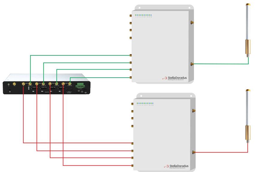
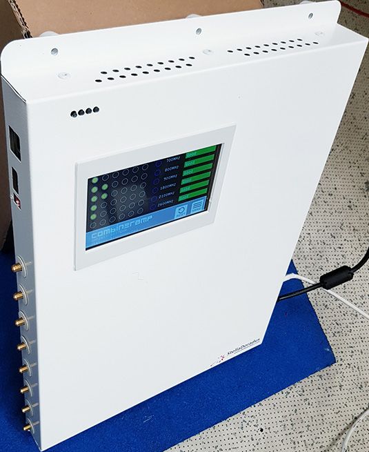
Diagrams

                                      Half MIMO setup (MIMO on DL only)

                     SMA ports for
                     internal ports

                     Battery enable

                     Debugging port
                                      Full MIMO setup
                     Ethernet

iC5-USA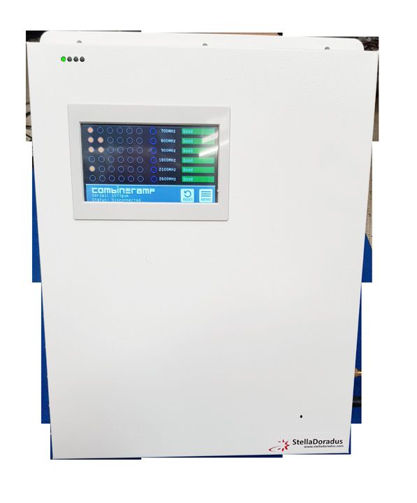
TouchScreen LCD Panel
Main screen:
APT-700 The green circles represent the downlink signal power (DL).
850 • 5-6 greeen circles means the signal is very good.
• 3-4 circles is a fair signal
AWS-1750 • 1-2 circles is a poor signal.
PCS-1900
The blue circles, when on, signify that this band is switched on and it is active.
2600 This will happen when a call or data session is initiated.
iCombinerAmp Once the call or data sessaion is over, the band switches off and the blue circle
also switches off.
The coloured rectangles to the right.
Good: means the band has no problems.
Adjusting: means the band is optimizing itself. This usually happens only once at bootup and only if there is alot of DL power.
Oscillation: means there is interferance between the indoor and outdoor antennas. You should isolate these antennas more
from each other to avoid oscillation. (available on R6 only)
Overpower: means there is a very strong outdoor signal. There is no need to do anything in this case as the repeater will
optimize itself to deal with this.
Shutdown: means that there is too much signal power outside and the repeater is shutting down the band to protect the
network.
Main Menu
Toggle bands: Switch on/off any band. Add attenuation to any band.
Access Pin: Enter your pin to access more setttings
Information: Information about the repeater.
Location info: Here you can enter the internal location of the
CombinerAmp inside the ship. This is usefull to see on the
onine dashboard.
Decibel page: The decibel page shows you detailed power and gain values
of the repeater.
Settings: Various settings in the CombinerAmp.
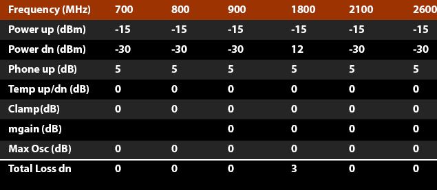
Decibel Page
Power up: This is the uplink power received by the repeater.
Power dn: This is the downlink power received by the repeater. (Signal power from
the outside antenna)
Phone up: This is the uplink AGC for phones passing nearby internal antennas.
Temp up/dn: This is the uplink and downlink AGC for when you are near a base station.
Clamp: This is the extra attenuation added for when there is an oscillation.
mgain: This is the manul gain. You can add your own attenuation to any band.
Sometimes this is neccessary for when there is too much power on any
one band.
Max Osc: Uplink and downlink oscilation. Whichever is higher, we add this to the attenuation.
Total loss: This is a sum of the temp up/dn + clamp + mgain + max osc. This value can be entered into the stellacontrol floorplan tool to
aid in designing repeater systems.
iC5-USA
iR6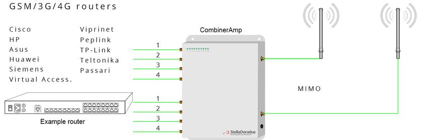
TouchScreen LCD Panel

      Information Page

      Type | Model:        Type (iC6-EU), Model standard
      Serial:              XX-XX-XX
      Version:             Software version.
      Installer name:      You can enter your company name from
                           the onlin dashboard.
      Internal location:   Here you can put in the location of the
                           CombinerAmp inside the ship.
      DHCP IP:             Local IP address
      IOT2 IP:             Cloud IP address
      Rebalance (min):     This is how often the CombinerAmp will reset / optimize itself.
      SW:HW:RB:WDT         These are counters for these occurances: software resets, hardware resets(power
                           removed), rebalances and watch dog timer resets.
      Temperature:         Temperature inside the repeater in degrees.
      TCPIP Count:         A metric for the quality of the internet connection.
      GPS Coords:          The location of the repeater can be know and represented on a map.
      GPS TIME | DATE:     Local time and date can be retrieved from the GPS module.
      Message Frequency    How oftern a message is sent by the repeater to the server.
      Ship mode:           If ship mode is enabled, this repeaters’ settings will be modified for this mode.

                                                    Toggle Bands:
                                                    Here we can switch on/off any or all bands. This can be
                                                    usefull when optimizing a repeater.
                              APT-700               For example, we can switch off 2600MHz to force 4G data to
                              850                   use 800 and 1800MHz.
                              AWS-1750
                                                    We can add attenuation to any band. This can be usefull
                              PCS-1900              if we have a particular band that is experiencing alot of
                              2600                  power.

                                                    Internal location:

                                                    Here you can input the internal location of the CombinerAmp.
                                                    Example: Floor3, sectionA, near stairs.
                                                    This location information is sent to the online dashboard where
                                                    it can be viewed alongside other stats about the CombinerAmp.

iC5-USA
 iR6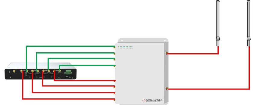
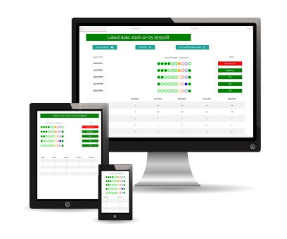
Online Dashboard Panel
Login to:
www.stellacontrol.com
1) Create a new ship and add your new device(s) to your new ship.
2) Now you can monitor and control all your ships/vehicles and devices.
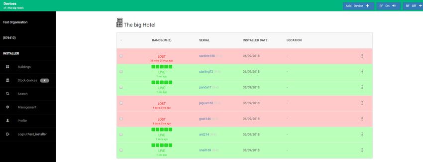
This image shows several devices installed in “the big hotel”, all being monitored
Alerts:
• Get alerted by email if there is any issues with your devices.
Remote Control from any computer/ phone:
• Switch On/Off, individual bands of any CombinerAmp.
• Switch off RF for one or all devices in a ship.
• Attenuate individual bands in any repeater by up to 18dB’s.
Monitor:
• Up/Downlink Power
• Up/Downlink Gains
• Up/Downlink AGC
• Up/Downlink Oscillations/feedback
• Temperature on PCB board
iC5-USA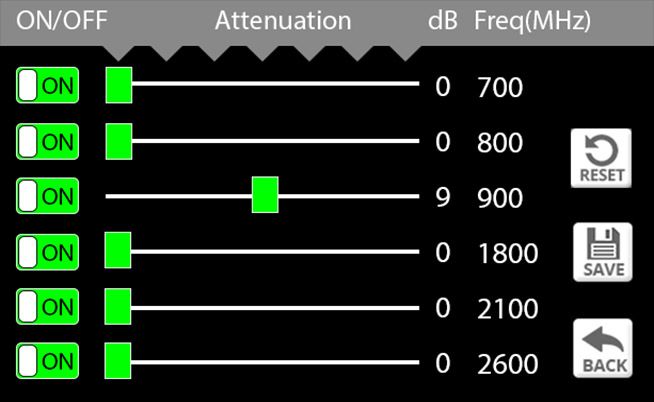
Specification
     Model number:                  iC5-USA
     Frequency                      APT700/850/AWS1750/PCS1900/2600Mhz
     Remote monitoring:

  Frequency Specifications:
  Frequency bands(Mhz):                			   (703-733) + (824-849) + (1700-1755) + (1850-1950) + (2500-2570) **UPLINK VALUES
  Gain:								                              Uplink Gp > 20dB       Downlink Gp> 20dB
  Pass band ripple: 						< 4dB
  I/O impedance:							50 ohm/SMA female connector
  Max uplink/downlink signal strength: 				  27dBm / -25dBm
  Ambient Temperature: 						-30oC to +70oC
  Power supply input: 						110 - 240V AC
  Power supply output:			                			 12v DC
  Oscillation Control 						Automatic
  Level Control:							Automatic*
  Uplink Switch Off						Yes**
  AGC Range							30db
  Surge protection							                    SMA connectors DC grounded, 12V DC port MOV protected

  Power Supply Specification:
 AC 								100-240V             50-60Hz
 DC input									         12V 		3.6A
 Typical power usage						 		33W

 Mechanical Specification:

 Length								35cm
 Width								30cm
 Depth								4.4cm
 Weight							  2kg
 Mounting							6 x 5mm holes for mounting

 * Automatically adjusts during installation. Thereafter, automatically adjusts for seasonal variation in pathloss between
 basestation and outdoor antenna.

 ** The up-link amplifiers switch off when the repeater is not in use. This reduces the uplink noise to almost zero. When
 the repeater is in use (eg. phone call being made), the up-link amplifier switches on for the duration of the call and a
 blue LED switches on indicating this is the case.

 Note: Specifications subject to change without notice.

iC5-USA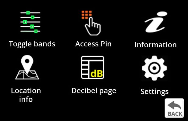
You can also read