Indicator for panel mounting, model 910.70 Anzeige für Schalttafeleinbau, model 910.70 Afficheur pour montage panneau, type 910.70 Indicador para ...
←
→
Page content transcription
If your browser does not render page correctly, please read the page content below
Operating instructions
                                Betriebsanleitung
                                Mode d‘emploi
                                Manual de instrucciones

Indicator for panel mounting, model 910.70                EN

Anzeige für Schalttafeleinbau, model 910.70               DE

Afficheur pour montage panneau, type 910.70               FR

Indicador para montaje en panel, modelo 910.70            ES

        Indicator for panel mounting, model 910.70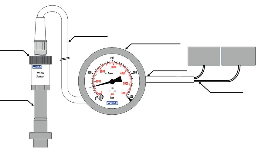
EN Operating instructions for model 910.70                                       Page        3 - 17

DE Betriebsanleitung für Typ 910.70                                              Seite      19 - 33

FR Mode d’emploi pour type 910.70                                                Page       35 - 49

ES Manual de instrucciones para modelo 910.70                                  Pagina       51 - 65

   © 05/2018 WIKA Alexander Wiegand SE & Co. KG
   All rights reserved. / Alle Rechte vorbehalten.
   WIKA® is a registered trademark in various countries.
   WIKA® ist eine geschützte Marke in verschiedenen Ländern.

   Prior to starting any work, read the operating instructions!
   Keep for later use!
                                                                                                        14125273.03 01/2022 EN/DE/FR/ES

   Vor Beginn aller Arbeiten Betriebsanleitung lesen!
   Zum späteren Gebrauch aufbewahren!

   Lire le mode d‘emploi avant de commencer toute opération !
   A conserver pour une utilisation ultérieure !

   ¡Leer el manual de instrucciones antes de comenzar cualquier trabajo!
   ¡Guardar el manual para una eventual consulta!

    2                          WIKA operating instructions indicator for panel mounting, model 910.70
Contents
Contents
EN
1. General information 4
2. Design and function 5
3. Safety 6
4. Transport, packaging and storage 9
5. Commissioning, operation 10
6. Faults 12
7. Maintenance and cleaning 14
8. Dismounting, return and disposal 15
9. Specifications 16
Declarations of conformity can be found online at www.wika.com.
14125273.03 01/2022 EN/DE/FR/ES
WIKA operating instructions indicator for panel mounting, model 910.70 31. General information
1. General information
■ The indicator described in the operating instructions has been designed and
manufactured using state-of-the-art technology. All components are subject to
EN stringent quality and environmental criteria during production. Our management
systems are certified to ISO 9001 and ISO 14001.
■ These operating instructions contain important information on handling the
instrument. Working safely requires that all safety instructions and work instructions
are observed.
■ Observe the relevant local accident prevention regulations and general safety
regulations for the instrument's range of use.
■ The operating instructions are part of the product and must be kept in the immediate
vicinity of the instrument and readily accessible to skilled personnel at any time. Pass
the operating instructions on to the next operator or owner of the instrument.
■ Skilled personnel must have carefully read and understood the operating instructions
prior to beginning any work.
■ The general terms and conditions contained in the sales documentation shall apply.
■ Subject to technical modifications.
■ Further information:
- Internet address: www.wika.de / www.wika.com
- Relevant data sheet: SP 20.02
- Application consultant: Tel.: +49 9372 132-0
Fax: +49 9372 132-406
info@wika.com
14125273.03 01/2022 EN/DE/FR/ES
4 WIKA operating instructions indicator for panel mounting, model 910.702. Design and function
2. Design and function
2.1 Installation example
EN
Sensor cable
Analogue display
Sensor
Power supply e.g. for SPS
DC 24 V 4 ... 20 mA
Supply line
Diaphragm Analogue output
seal (optional)
LED
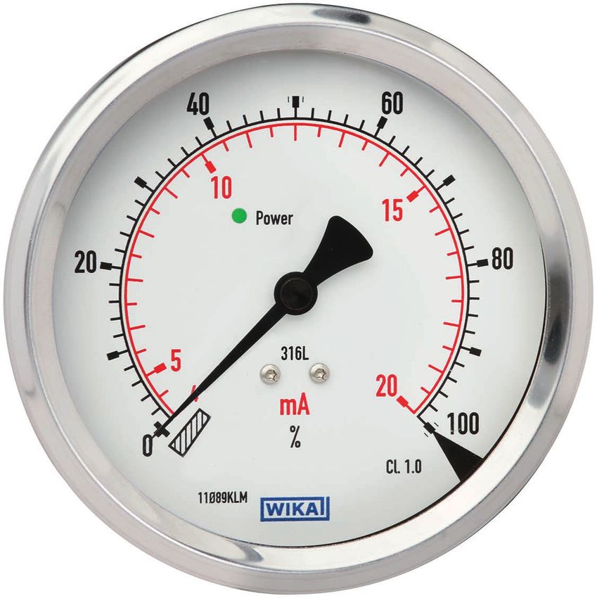
2.2 Description
After connection to the power supply, the indicator will initialise independently. As soon
as the LED lights up green continuously, the indicator is ready for use. A flashing LED
indicates that the output signal is either above or below the scale range. From the
pointer position, the operator can immediately know whether the indicator is working
correctly.
The 910.70 indicator is optionally available with a 4 ... 20 mA output signal. With this
option, the measurement can be evaluated away from the measuring point, e.g. at a
PLC. The optional analogue output requires no additional adjustment and outputs the
sensor signal as 4 ... 20 mA.
2.3 Scope of delivery
Cross-check scope of delivery with delivery note.
14125273.03 01/2022 EN/DE/FR/ES
WIKA operating instructions indicator for panel mounting, model 910.70 53. Safety
3. Safety
3.1 Explanation of symbols
EN WARNING!
... indicates a potentially dangerous situation that can result in serious
injury or death, if not avoided.
CAUTION!
... indicates a potentially dangerous situation that can result in light injuries
or damage to property or the environment, if not avoided.
Information
... points out useful tips, recommendations and information for efficient
and trouble-free operation.
3.2 Intended use
The model 910.70 indicator is an accessory and displays the measured values of an
electrical sensor with a 4 ... 20 mA output signal on a dial. The case of the indicator is
designed for panel mounting.
The indicator offers an optional output signal for 4 … 20 mA.
The indicator has been designed for industrial applications in indoor and outdoor areas.
The instrument has been designed and built solely for the intended use described here,
and may only be used accordingly.
Only use the instrument in applications that lie within its technical performance limits
(e.g. max. ambient temperature, material compatibility, ...).
→ For performance limits see chapter 9 “Specifications”.
Improper handling or operation of the instrument outside of its technical specifications
requires the instrument to be taken out of service immediately and inspected by an
authorised WIKA service engineer.
Handle electronic precision instruments with the required care (protect from humidity,
impacts, strong magnetic fields, static electricity and extreme temperatures, do not
insert any objects into the instrument or its openings). Plugs and sockets must be
14125273.03 01/2022 EN/DE/FR/ES
protected from contamination.
The manufacturer shall not be liable for claims of any type based on operation contrary
to the intended use.
6 WIKA operating instructions indicator for panel mounting, model 910.703. Safety
3.3 Improper use
WARNING!
Injuries through improper use
Improper use of the instrument can lead to hazardous situations and
injuries. EN
▶ Refrain from unauthorised modifications to the instrument.
▶ Do not use the instrument within hazardous areas.
Any use beyond or different to the intended use is considered as improper use.
Do not use this instrument in safety or emergency stop devices.
3.4 Responsibility of the operator
The instrument is used in the industrial sector. The operator is therefore responsible for
legal obligations regarding safety at work.
The safety instructions within these operating instructions, as well as the safety,
accident prevention and environmental protection regulations for the application area
must be maintained.
The operator is obliged to maintain the product label in a legible condition.
3.5 Personnel qualification
WARNING!
Risk of injury should qualification be insufficient
Improper handling can result in considerable injury and damage to
equipment.
▶ The activities described in these operating instructions may only be
carried out by skilled personnel who have the qualifications described
below.
Skilled electrical personnel
Skilled electrical personnel are understood to be personnel who, based on their
technical training, know-how and experience as well as their knowledge of country-
specific regulations, current standards and directives, are capable of carrying out work
on electrical systems and independently recognising and avoiding potential hazards.
The skilled electrical personnel have been specifically trained for the work environment
they are working in and know the relevant standards and regulations. The skilled
14125273.03 01/2022 EN/DE/FR/ES
electrical personnel must comply with current legal accident prevention regulations.
Operating personnel
The personnel trained by the operator are understood to be personnel who, based
on their education, knowledge and experience, are capable of carrying out the work
described and independently recognising potential hazards.
Special operating conditions require further appropriate knowledge, e.g. of aggressive
media.
WIKA operating instructions indicator for panel mounting, model 910.70 73. Safety
3.6 Personal protective equipment
The personal protective equipment is designed to protect the skilled personnel from
hazards that could impair their safety or health during work. When carrying out the
various tasks on and with the instrument, the skilled personnel must wear personal
EN protective equipment.
Follow the instructions displayed in the work area regarding personal protective
equipment!
3.7 Labelling, safety marks
Product label on the case circumference
Dial with traceable serial number (example)
XXXXXX
Model
Power supply
Output signal
Input signal
Serial number
Symbols
14125273.03 01/2022 EN/DE/FR/ES
Before mounting and commissioning the instrument, ensure you read
the operating instructions!
Do not dispose of with household waste. Ensure a proper disposal in
accordance with national regulations.
8 WIKA operating instructions indicator for panel mounting, model 910.704. Transport, packaging and storage
4. Transport, packaging and storage
4.1 Transport
Check the indicator for any damage that may have been caused by transport.
Obvious damage must be reported immediately. EN
CAUTION!
Damage through improper transport
With improper transport, a high level of damage to property can occur.
▶ When unloading packed goods upon delivery as well as during internal
transport, proceed carefully and observe the symbols on the packaging.
▶ With internal transport, observe the instructions in chapter 5.2
“Packaging and storage”.
If the instrument is transported from a cold into a warm environment, the formation of
condensation may result in instrument malfunction. Before putting it back into operation,
wait for the instrument temperature and the room temperature to equalise.
4.2 Packaging and storage
Do not remove packaging until just before mounting.
Keep the packaging as it will provide optimum protection during transport (e.g. change
in installation site, sending for repair).
Permissible conditions at the place of storage:
■ Storage temperature: -25 ... +70 °C
■ Humidity: 10 ... 95 % r. h. (non-condensing)
Avoid exposure to the following factors:
■ Direct sunlight or proximity to hot objects
■ Mechanical vibration, mechanical shock (putting it down hard)
■ Soot, vapour, dust and corrosive gases
■ Hazardous environments, flammable atmospheres
Store the instrument in its original packaging in a location that fulfils the conditions
listed above. If the original packaging is not available, pack and store the instrument as
described below:
1. Wrap the instrument in an antistatic plastic film.
2. Place the instrument, along with the shock-absorbent material, in the packaging.
14125273.03 01/2022 EN/DE/FR/ES
3. If stored for a prolonged period of time (more than 30 days), place a bag containing a
desiccant inside the packaging.
WIKA operating instructions indicator for panel mounting, model 910.70 95. Commissioning, operation
5. Commissioning, operation
Personnel: Skilled electrical personnel
Tools: Slotted screwdriver and tools for cable preparation
EN
5.1 Mechanical mounting
Required panel cutout: Ø 104 ±0.5 mm
Panel
Mounting bracket
Spacer part
Spacer disc
Mounting slot
1. Slide and align the indicator into the panel cutout from the front, so the front bezel
lies flat on the panel.
2. Assemble the mounting bracket with the 3 spacer rings as shown below.
With the screwdriver, set the position of the 3 spacer parts so that these, from the
control panel, are positioned approx. 3 mm in front of the mounting slots. 14125273.03 01/2022 EN/DE/FR/ES
3. Place the spacer discs of the mounting bracket in the mounting slots.
4. Screw in the 3 spacer parts evenly using the slotted screwdriver, so that the indicator
is evenly and solidly mounted in the control panel.
10 WIKA operating instructions indicator for panel mounting, model 910.705. Commissioning, operation
5.2 Electrical mounting
The power supply unit used for the voltage supply of the instrument must fulfil the
demands on the required power supply, see chapter 9 “Specifications”.
For the electrical connection of the instrument, only the original cables delivered from EN
WIKA for this instrument may be used.
WARNING!
Before commissioning, ensure that the voltage supply is turned off.
Wiring
Analogue output (optional)
Connector: Connection for supply cable (4-pin)
Cable assignment
4 3 Pin Function Wire colour
1 2 1 Analogue output (+) BN
2 Power supply (DC 14 ... 24 V) WH
4 3 3 Analogue output (-) BL
1 2 4 Power supply (GND / 0 V) BC
Sensor input
Female connector: Connection for sensor cable (4-pin)
1. Using the sensor cable, connect the instrument with the sensor
2. Connect the supply cable to the indicator
3. Switch on the power supply
The indicator will be initialised. If the LED lights up green, then the indicator is ready for
use. If the LED flashes green, the output signal is either above or below the scale range.
The LED statuses are described in chapter 6 “Faults”.
14125273.03 01/2022 EN/DE/FR/ES
WIKA operating instructions indicator for panel mounting, model 910.70 116. Faults
6. Faults
Personnel: Skilled electrical personnel
EN CAUTION!
Physical injuries and damage to property and the environment
If faults cannot be eliminated by means of the listed measures, the
instrument must be taken out of operation immediately.
▶ Ensure that there is no longer any signal present and protect against
being put into operation accidentally.
▶ Contact the manufacturer.
▶ If a return is needed, please follow the instructions given in chapter 8.1
“Return”.
For contact details see chapter 1 “General information” or the back page
of the operating instructions.
6.1 Dial markings and LED status
Dial status Description Operating status
Power LED lights up green. Normal operation
40 60 Pointer is within the scale.
10
Power 15 Analogue output is in the
20 80 range of 4 ... 20 mA
5 316L
4 20
mA
% 100
0
Power LED flashes green. After switching on the analogue
40 60 Pointer is below the scale. display, an initialisation process
is performed. Wait 5 seconds.
10
Power 15 Analogue output in the range
20 80 of 4 ... 20 mA
5 316L
14125273.03 01/2022 EN/DE/FR/ES
4 20
mA
% 100
0
12 WIKA operating instructions indicator for panel mounting, model 910.706. Faults
Dial status Description Operating status
Power LED flashes red. The sensor signal is between
40 60 Pointer is above the full scale 20.5 … 21 mA 1).
value. Error signal is suppressed for a
10
Power 15 few seconds. EN
20 80 Analogue output: > 20 mA
Check sensor.
5 316L
4 20
mA
% 100
0
Power LED flashes red. Sensor signal is < 3.6 mA 1)
40 60 Pointer is below the scale. Error signal is suppressed for a
10
few seconds.
Power 15 Analogue output: < 4 mA
20 80 Check sensor cable and sensor.
5 316L
4 20
mA
% 100
0
Power LED does not light up. Check power supply
40 60 Pointer is below the scale.
10
Power 15 Analogue output: > 21 mA
20 80
5 316L
4 20
mA
% 100
0
1) In accordance with recommendation NE43 of NAMUR (international user association of automation technology in process
industries)
14125273.03 01/2022 EN/DE/FR/ES
WIKA operating instructions indicator for panel mounting, model 910.70 137. Maintenance and cleaning
7. Maintenance and cleaning
Personnel: Skilled electrical personnel
EN
For contact details see chapter 1 “General information” or the back page
of the operating instructions.
7.1 Maintenance
This instrument is maintenance-free.
7.2 Cleaning
CAUTION!
Physical injuries and damage to property and the environment
Improper cleaning may lead to physical injuries and damage to property
and the environment.
▶ Carry out the cleaning process as described below.
1. Prior to cleaning, properly disconnect the indicator from the power supply.
2. Clean the instrument with a moist cloth.
Electrical connections must not come into contact with moisture!
CAUTION!
Damage to property
Improper cleaning may lead to damage to the instrument!
▶ Do not use any aggressive cleaning agents.
▶ Do not use any hard or pointed objects for cleaning.
14125273.03 01/2022 EN/DE/FR/ES
14 WIKA operating instructions indicator for panel mounting, model 910.708. Return and disposal
8. Return and disposal
Personnel: Skilled electrical personnel
8.1 Return EN
Strictly observe the following when shipping the instrument:
All instruments delivered to WIKA must be free from any kind of hazardous substances
(acids, bases, solutions, etc.) and must therefore be cleaned before being returned.
▶ Clean the instrument, see chapter 7.2 “Cleaning”.
When returning the instrument, use the original packaging or a suitable transport
packaging.
To avoid damage:
1. Wrap the instrument in an antistatic plastic film.
2. Place the instrument, along with shock-absorbent material, in the packaging.
Place shock-absorbent material evenly on all sides of the transport packaging.
3. If possible, place a bag containing a desiccant inside the packaging.
4. Label the shipment as carriage of a highly sensitive measuring instrument.
Information on returns can be found under the heading “Service” on our
local website.
8.3 Disposal
Incorrect disposal can put the environment at risk.
Dispose of instrument components and packaging materials in an environmentally
compatible way and in accordance with the country-specific waste disposal regulations.
14125273.03 01/2022 EN/DE/FR/ES
WIKA operating instructions indicator for panel mounting, model 910.70 159. Specifications
9. Specifications
Specifications Model 910.70
Indicator
EN Principle A digitally controlled stepper motor drives the pointer shaft
Dial White, black lettering
Scale range 270°
Measuring time Max. 30 % of full scale / s
Sensor input
Input signal 4 ... 20 mA, 2-wire
Electrical connection Circular connector M12 x 1, 4-pin; nickel-plated brass
Accuracy 0.75 % of measuring span.
Voltage supply
Power supply US DC 14 ... 30 V, max. 0.2 A
Electrical connection Connector M12 x 1, 4-pin
Output signal
Output signal 4 ... 20 mA, 2-wire, passive, galvanically isolated
Permissible max. load RA RA ≤ (UB - 12 V)/0.02 A with RA in Ω and UB in V, however
max. 600 Ω
Power supply UB DC 12 V< UB < 30 V
Cable
Power cord Length: ≤ 5 m, only use of original cable is permitted
Sensor cable Length: ≤ 3 m, only use of original cable is permitted
Permissible ambient conditions
Operating temperature 0 ... 60 °C
Storage temperature -25 ... +70 °C
Permissible air humidity 10 ... 95 % r. h. (non-condensing)
Case
Material Stainless steel
Ingress protection IP65/IP67
14125273.03 01/2022 EN/DE/FR/ES
per IEC/EN 60529
Weight Approx. 365 g
Mounting With mounting bracket
Dimensions See chapter 9.1 “Dimensions”
16 WIKA operating instructions indicator for panel mounting, model 910.709. Specifications
9.1 Dimensions in mm [in]
EN
For further specifications see WIKA data sheet SP 20.02 and the order documentation.
14125273.03 01/2022 EN/DE/FR/ES
WIKA operating instructions indicator for panel mounting, model 910.70 1714125273.03 01/2022 EN/DE/FR/ES 18 WIKA operating instructions indicator for panel mounting, model 910.70
Inhalt

                                  Inhalt
                                  1.    Allgemeines                                                    20
                                  2.    Aufbau und Funktion                                            21   DE
                                  3.    Sicherheit                                                     22
                                  4.    Transport, Verpackung und Lagerung                             25
                                  5.    Inbetriebnahme, Betrieb                                        26
                                  6.    Störungen                                                      28
                                  7.    Wartung und Reinigung                                          30
                                  8.    Demontage, Rücksendung und Entsorgung                          31
                                  9.    Technische Daten                                               32

                                  Konformitätserklärungen finden Sie online unter www.wika.de.
14125273.03 01/2022 EN/DE/FR/ES

                                   WIKA Betriebsanleitung, Anzeige zum Schalttafeleinbau, Typ 910.70   19
1. Allgemeines
1. Allgemeines
■ Die in der Betriebsanleitung beschriebene Anzeige wird nach dem aktuellen Stand
der Technik konstruiert und gefertigt. Alle Komponenten unterliegen während der
Fertigung strengen Qualitäts- und Umweltkriterien. Unsere Managementsysteme
sind nach ISO 9001 und ISO 14001 zertifiziert.
■ Diese Betriebsanleitung gibt wichtige Hinweise zum Umgang mit dem Gerät.
DE Voraussetzung für sicheres Arbeiten ist die Einhaltung aller angegebenen
Sicherheitshinweise und Handlungsanweisungen.
■ Die für den Einsatzbereich des Gerätes geltenden örtlichen
Unfallverhütungsvorschriften und allgemeinen Sicherheitsbestimmungen einhalten.
■ Die Betriebsanleitung ist Produktbestandteil und muss in unmittelbarer Nähe
des Gerätes für das Fachpersonal jederzeit zugänglich aufbewahrt werden.
Betriebsanleitung an nachfolgende Benutzer oder Besitzer des Gerätes weitergeben.
■ Das Fachpersonal muss die Betriebsanleitung vor Beginn aller Arbeiten sorgfältig
durchgelesen und verstanden haben.
■ Es gelten die allgemeinen Geschäftsbedingungen in den Verkaufsunterlagen.
■ Technische Änderungen vorbehalten.
■ Weitere Informationen:
- Internet-Adresse: www.wika.de / www.wika.com
- Zugehöriges Datenblatt: SP 20.02
- Anwendungsberater: Tel.: +49 9372 132-0
Fax: +49 9372 132-406
info@wika.com
14125273.03 01/2022 EN/DE/FR/ES
20 WIKA Betriebsanleitung, Anzeige zum Schalttafeleinbau, Typ 910.702. Aufbau und Funktion
2. Aufbau und Funktion
2.1 Einbaubeispiel
Sensorkabel
DE
Analoge Anzeige
Sensor
Hilfsenergie z. B. für SPS
DC 24 V 4 ... 20 mA
Zuleitung
Analogausgang
Druckmittler (optional)
LED
2.2 Beschreibung
Nach dem Anschluss an die Stromversorgung initialisiert sich die Anzeige selbstständig.
Sobald die LED dauerhaft grün leuchtet, ist die Anzeige funktionsbereit. Eine blinkende
LED zeigt an, dass das Ausgangssignal oberhalb oder unterhalb des Anzeigebereiches
liegt. Anhand der Zeigerstellung kann der Bediener sofort erkennen, ob die Anzeige
korrekt arbeitet.
Die Anzeige 910.70 ist optional mit einem Analogausgang 4 ... 20 mA lieferbar. Mit
dieser Option kann die Messung fernab von der Messstelle, z. B. auf einer SPS,
ausgewertet werden. Der optionale Analogausgang erfordert keinen zusätzlichen
Abgleich und gibt das Sensorsignal von 4 ... 20 mA aus.
2.3 Lieferumfang
Lieferumfang mit dem Lieferschein abgleichen.
14125273.03 01/2022 EN/DE/FR/ES
WIKA Betriebsanleitung, Anzeige zum Schalttafeleinbau, Typ 910.70 213. Sicherheit
3. Sicherheit
3.1 Symbolerklärung
WARNUNG!
... weist auf eine möglicherweise gefährliche Situation hin, die zum Tod
oder zu schweren Verletzungen führen kann, wenn sie nicht gemieden
wird.
DE
VORSICHT!
... weist auf eine möglicherweise gefährliche Situation hin, die zu
geringfügigen oder leichten Verletzungen bzw. Sach- und Umweltschäden
führen kann, wenn sie nicht gemieden wird.
Information
... hebt nützliche Tipps und Empfehlungen sowie Informationen für einen
effizienten und störungsfreien Betrieb hervor.
3.2 Bestimmungsgemäße Verwendung
Die Anzeige Typ 910.70 ist Zubehör und zeigt Messwerte eines elektrischen Sensors
mit 4 ... 20 mA-Ausgangssignal auf einem Zifferblatt an. Das Gehäuse der Anzeige ist
für den Einbau in Schalttafeln vorgesehen.
Die Anzeige liefert optional ein Ausgangssignal für 4 ... 20 mA.
Die Anzeige wurde für gewerbliche Anwendungen im Innen- und Außenbereich
konzipiert.
Das Gerät ist ausschließlich für den hier beschriebenen bestimmungsgemäßen
Verwendungszweck konzipiert und konstruiert und darf nur dementsprechend
verwendet werden.
Das Gerät nur in Anwendungen verwenden, die innerhalb seiner technischen
Leistungsgrenzen liegen (z. B. max. Umgebungstemperatur, Materialverträglichkeit, ...).
→ Leistungsgrenzen siehe Kapitel 9 „Technische Daten“.
Eine unsachgemäße Handhabung oder ein Betreiben des Gerätes außerhalb der
technischen Spezifikationen macht die sofortige Stilllegung und Überprüfung durch
einen autorisierten WIKA-Servicemitarbeiter erforderlich.
14125273.03 01/2022 EN/DE/FR/ES
Elektronische Präzisionsgeräte mit erforderlicher Sorgfalt behandeln (vor Nässe,
Stößen, starken Magnetfeldern, statischer Elektrizität und extremen Temperaturen
schützen, keine Gegenstände in das Gerät bzw. Öffnungen einführen). Stecker und
Buchsen vor Verschmutzung schützen.
Ansprüche jeglicher Art aufgrund von nicht bestimmungsgemäßer Verwendung sind
ausgeschlossen.
22 WIKA Betriebsanleitung, Anzeige zum Schalttafeleinbau, Typ 910.703. Sicherheit
3.3 Fehlgebrauch
WARNUNG!
Verletzungen durch Fehlgebrauch
Fehlgebrauch des Gerätes kann zu gefährlichen Situationen und
Verletzungen führen.
▶ Eigenmächtige Umbauten am Gerät unterlassen.
▶ Gerät nicht in explosionsgefährdeten Bereichen einsetzen.
Jede über die bestimmungsgemäße Verwendung hinausgehende oder andersartige DE
Benutzung gilt als Fehlgebrauch.
Dieses Gerät nicht in Sicherheits- oder in Not-Aus-Einrichtungen benutzen.
3.4 Verantwortung des Betreibers
Das Gerät wird im gewerblichen Bereich eingesetzt. Der Betreiber unterliegt daher den
gesetzlichen Pflichten zur Arbeitssicherheit.
Die Sicherheitshinweise dieser Betriebsanleitung, sowie die für den Einsatzbereich
des Gerätes gültigen Sicherheits-, Unfallverhütungs- und Umweltschutzvorschriften
einhalten.
Der Betreiber ist verpflichtet das Typenschild lesbar zu halten.
3.5 Personalqualifikation
WARNUNG!
Verletzungsgefahr bei unzureichender Qualifikation
Unsachgemäßer Umgang kann zu erheblichen Personen- und
Sachschäden führen.
▶ Die in dieser Betriebsanleitung beschriebenen Tätigkeiten nur durch
Fachpersonal nachfolgend beschriebener Qualifikation durchführen
lassen.
Elektrofachpersonal
Das Elektrofachpersonal ist aufgrund seiner fachlichen Ausbildung, Kenntnisse und
Erfahrungen sowie Kenntnis der landesspezifischen Vorschriften, geltenden Normen
und Richtlinien in der Lage, Arbeiten an elektrischen Anlagen auszuführen und
mögliche Gefahren selbstständig zu erkennen und zu vermeiden.
Das Elektrofachpersonal ist speziell für das Arbeitsumfeld, in dem es tätig
ist, ausgebildet und kennt die relevanten Normen und Bestimmungen. Das
14125273.03 01/2022 EN/DE/FR/ES
Elektrofachpersonal muss die Bestimmungen der geltenden gesetzlichen Vorschriften
zur Unfallverhütung erfüllen.
Bedienpersonal
Das vom Betreiber geschulte Personal ist aufgrund seiner Bildung, Kenntnisse und
Erfahrungen in der Lage, die beschriebenen Arbeiten auszuführen und mögliche
Gefahren selbstständig zu erkennen.
Spezielle Einsatzbedingungen verlangen weiteres entsprechendes Wissen, z. B. über
aggressive Messstoffe.
WIKA Betriebsanleitung, Anzeige zum Schalttafeleinbau, Typ 910.70 233. Sicherheit
3.6 Persönliche Schutzausrüstung
Die persönliche Schutzausrüstung dient dazu, das Fachpersonal gegen Gefahren
zu schützen, die dessen Sicherheit oder Gesundheit bei der Arbeit beeinträchtigen
könnten. Beim Ausführen der verschiedenen Arbeiten an und mit dem Gerät muss das
Fachpersonal persönliche Schutzausrüstung tragen.
Im Arbeitsbereich angebrachte Hinweise zur persönlichen Schutzausrüstung
befolgen!
DE
3.7 Beschilderung, Sicherheitskennzeichnungen
Typenschild am Gehäuseumfang
Zifferblatt mit rückverfolgbarer Seriennummer (Beispiel)
XXXXXX
Typ
Hilfsenergie
Ausgangssignal
Eingangssignal
Seriennummer
Symbole
14125273.03 01/2022 EN/DE/FR/ES
Vor Montage und Inbetriebnahme des Gerätes unbedingt die
Betriebsanleitung lesen!
Nicht mit dem Hausmüll entsorgen. Für eine geordnete Entsorgung
gemäß nationaler Vorgaben sorgen.
24 WIKA Betriebsanleitung, Anzeige zum Schalttafeleinbau, Typ 910.704. Transport, Verpackung und Lagerung
4. Transport, Verpackung und Lagerung
4.1 Transport
Anzeige auf eventuell vorhandene Transportschäden untersuchen.
Offensichtliche Schäden unverzüglich mitteilen.
VORSICHT!
Beschädigungen durch unsachgemäßen Transport DE
Bei unsachgemäßem Transport können Sachschäden in erheblicher Höhe
entstehen.
▶ Beim Abladen der Packstücke bei Anlieferung sowie innerbetrieblichem
Transport vorsichtig vorgehen und die Symbole auf der Verpackung
beachten.
▶ Bei innerbetrieblichem Transport die Hinweise unter Kapitel 5.2
„Verpackung und Lagerung“ beachten.
Wird das Gerät von einer kalten in eine warme Umgebung transportiert, so kann durch
Kondensatbildung eine Störung der Gerätefunktion eintreten. Vor einer erneuten
Inbetriebnahme die Angleichung der Gerätetemperatur an die Raumtemperatur
abwarten.
4.2 Verpackung und Lagerung
Verpackung erst unmittelbar vor der Montage entfernen.
Die Verpackung aufbewahren, denn diese bietet bei einem Transport einen optimalen
Schutz (z. B. wechselnder Einbauort, Reparatursendung).
Zulässige Bedingungen am Lagerort:
■ Lagertemperatur: -25 ... +70 °C
■ Feuchte: 10 ... 95 % r. F. (nicht kondensierend)
Folgende Einflüsse vermeiden:
■ Direktes Sonnenlicht oder Nähe zu heißen Gegenständen
■ Mechanische Vibration, mechanischer Schock (hartes Aufstellen)
■ Ruß, Dampf, Staub und korrosive Gase
■ Explosionsgefährdete Umgebung, entzündliche Atmosphären
Das Gerät in der Originalverpackung an einem Ort, der die oben gelisteten
Bedingungen erfüllt, lagern. Wenn die Originalverpackung nicht vorhanden ist, dann das
14125273.03 01/2022 EN/DE/FR/ES
Gerät wie folgt verpacken und lagern:
1. Das Gerät in eine antistatische Plastikfolie einhüllen.
2. Das Gerät mit dem Dämmmaterial in der Verpackung platzieren.
3. Bei längerer Einlagerung (mehr als 30 Tage) einen Beutel mit Trocknungsmittel der
Verpackung beilegen.
WIKA Betriebsanleitung, Anzeige zum Schalttafeleinbau, Typ 910.70 255. Inbetriebnahme, Betrieb
5. Inbetriebnahme, Betrieb
Personal: Elektrofachpersonal
Werkzeuge: Schlitzschraubendreher und Werkzeuge zur Kabelkonfektionierung
5.1 Mechanische Montage
Erforderlicher Schalttafelausschnitt: Ø 104 ±0,5 mm
DE
Schalttafel
Befestigungsbügel
Distanzstück
Distanzscheibe
Befestigungsnut
1. Anzeige von vorn in den Schalttafelausschnitt einschieben und so ausrichten, dass
der Frontring flach auf der Schalttafel aufliegt.
2. Den Befestigungsbügel mit den 3 Abstandsringen wie unten gezeigt montieren.
Mit dem Schraubendreher die Position der 3 Distanzstücke so einstellen, dass diese
von der Schalttafel ausgehend ca. 3 mm vor den Befestigungsnuten positioniert
sind.
14125273.03 01/2022 EN/DE/FR/ES
3. Die Distanzscheiben des Befestigungsbügels in die Befestigungsnuten einlegen.
4. Gleichmäßig die 3 Distanzstücke mit dem Schlitzschraubendreher einschrauben,
sodass die Anzeige gleichmäßig und fest in der Schalttafel montiert ist.
26 WIKA Betriebsanleitung, Anzeige zum Schalttafeleinbau, Typ 910.705. Inbetriebnahme, Betrieb
5.2 Elektrische Montage
Das verwendete Netzteil für die Spannungsversorgung des Gerätes muss die
Anforderungen an die benötigte Hilfsenergie, siehe Kapitel 9 „Technische Daten“,
erfüllen.
Für den elektrischen Anschluss des Gerätes dürfen nur die von WIKA gelieferten
Originalkabel für dieses Gerät verwendet werden.
DE
WARNUNG!
Vor der Inbetriebnahme sicherstellen, dass die Spannungsversorgung
ausgeschaltet ist.
Verdrahtung
Analogausgang (optional)
Stecker: Anschluss für Versorgungskabel (4-polig)
Kabelbelegung
4 3 Pin Funktion Aderfarbe
1 2 1 Analogausgang (+) BN
2 Hilfsenergie (DC 14 ... 24 V) WH
4 3 3 Analogausgang (-) BL
1 2 4 Hilfsenergie (GND / 0 V) BC
Sensoreingang
Buchse: Anschluss für Sensorkabel (4-polig)
1. Mit dem Sensorkabel das Gerät mit dem Sensor verbinden
2. Versorgungskabel an die Anzeige anschließen
3. Hilfsenergie einschalten
Die Anzeige wird initialisiert. Leuchtet die LED grün, so ist die Anzeige funktionsbereit.
Blinkt die LED grün, liegt das Ausgangssignal oberhalb oder unterhalb des
Anzeigebereiches.
14125273.03 01/2022 EN/DE/FR/ES
Die LED-Stati sind in Kapitel 6 „Störungen“ beschrieben.
WIKA Betriebsanleitung, Anzeige zum Schalttafeleinbau, Typ 910.70 276. Störungen
6. Störungen
Personal: Elektrofachpersonal
VORSICHT!
Körperverletzungen, Sach- und Umweltschäden
Können Störungen mit Hilfe der aufgeführten Maßnahmen nicht beseitigt
DE werden, Gerät unverzüglich außer Betrieb setzen.
▶ Sicherstellen, dass kein Signal mehr anliegt und gegen versehentliche
Inbetriebnahme schützen.
▶ Kontakt mit dem Hersteller aufnehmen.
▶ Bei notwendiger Rücksendung die Hinweise unter Kapitel 8.1
„Rücksendung“ beachten.
Kontaktdaten siehe Kapitel 1 „Allgemeines“ oder Rückseite der
Betriebsanleitung.
6.1 Zifferblattmarkierungen und LED-Status
Status Zifferblatt Beschreibung Betriebsstatus
Power-LED leuchtet grün. Normalbetrieb
40 60 Zeiger befindet sich innerhalb
der Skale.
10
Power 15
20 80 Analogausgang ist im Bereich
von 4 ... 20 mA
5 316L
4 20
mA
% 100
0
Power-LED blinkt grün. Nach dem Einschalten
40 60 Zeiger befindet sich unterhalb der Analoganzeige wird
der Skale. ein Initialisierungsprozess
10
Power 15 durchgeführt. 5 Sekunden
20 80 Analogausgang ist im Bereich warten.
von 4 ... 20 mA
5 316L
14125273.03 01/2022 EN/DE/FR/ES
4 20
mA
% 100
0
28 WIKA Betriebsanleitung, Anzeige zum Schalttafeleinbau, Typ 910.706. Störungen
Status Zifferblatt Beschreibung Betriebsstatus
Power-LED blinkt rot. Das Sensorsignal liegt zwischen
40 60 Zeiger befindet sich oberhalb 20,5 … 21 mA 1).
10
des Skalenendwertes. Fehlersignal wird einige
Power 15 Sekunden unterdrückt.
20 80 Analogausgang: > 20 mA
Sensor prüfen.
5 316L
4
mA
20
100
DE
0 %
Power-LED blinkt rot. Sensorsignal ist < 3,6 mA 1)
40 60 Zeiger befindet sich unterhalb Fehlersignal wird einige
10
der Skale. Sekunden unterdrückt.
Power 15
20 80 Analogausgang: < 4 mA Sensorkabel und Sensor prüfen.
5 316L
4 20
mA
% 100
0
Power-LED leuchtet nicht. Hilfsenergie prüfen
40 60 Zeiger befindet sich unterhalb
10
der Skale.
Power 15
20 80
Analogausgang: > 21 mA
5 316L
4 20
mA
% 100
0
1) Gemäß Empfehlung NE43 der NAMUR (internationaler Verband der Anwender von Automatisierungstechnik der
Prozessindustrie)
14125273.03 01/2022 EN/DE/FR/ES
WIKA Betriebsanleitung, Anzeige zum Schalttafeleinbau, Typ 910.70 297. Wartung und Reinigung
7. Wartung und Reinigung
Personal: Elektrofachpersonal
Kontaktdaten siehe Kapitel 1 „Allgemeines“ oder Rückseite der
Betriebsanleitung.
DE
7.1 Wartung
Dieses Gerät ist wartungsfrei.
7.2 Reinigung
VORSICHT!
Körperverletzungen, Sach- und Umweltschäden
Eine unsachgemäße Reinigung führt zu Körperverletzungen, Sach- und
Umweltschäden.
▶ Reinigungsvorgang wie folgt beschrieben durchführen.
1. Vor der Reinigung die Anzeige ordnungsgemäß von der Stromversorgung trennen.
2. Das Gerät mit einem feuchten Tuch reinigen.
Elektrische Anschlüsse nicht mit Feuchtigkeit in Berührung bringen!
VORSICHT!
Sachbeschädigung
Eine unsachgemäße Reinigung führt zur Beschädigung des Gerätes!
▶ Keine aggressiven Reinigungsmittel verwenden.
▶ Keine harten und spitzen Gegenstände zur Reinigung verwenden.
14125273.03 01/2022 EN/DE/FR/ES
30 WIKA Betriebsanleitung, Anzeige zum Schalttafeleinbau, Typ 910.708. Rücksendung und Entsorgung
8. Rücksendung und Entsorgung
Personal: Elektrofachpersonal
8.1 Rücksendung
Beim Versand des Gerätes unbedingt beachten:
Alle an WIKA gelieferten Geräte müssen frei von Gefahrstoffen (Säuren, Laugen,
Lösungen, etc.) sein und sind daher vor der Rücksendung zu reinigen. DE
▶ Gerät reinigen, siehe Kapitel 7.2 „Reinigung“.
Zur Rücksendung des Gerätes die Originalverpackung oder eine geeignete
Transportverpackung verwenden.
Um Schäden zu vermeiden:
1. Das Gerät in eine antistatische Plastikfolie einhüllen.
2. Das Gerät mit dem Dämmmaterial in der Verpackung platzieren.
Zu allen Seiten der Transportverpackung gleichmäßig dämmen.
3. Wenn möglich, einen Beutel mit Trocknungsmittel der Verpackung beifügen.
4. Sendung als Transport eines hochempfindlichen Messgerätes kennzeichnen.
Hinweise zur Rücksendung befinden sich in der Rubrik „Service“ auf
unserer lokalen Internetseite.
8.3 Entsorgung
Durch falsche Entsorgung können Gefahren für die Umwelt entstehen.
Gerätekomponenten und Verpackungsmaterialien entsprechend den
landesspezifischen Abfallbehandlungs- und Entsorgungsvorschriften umweltgerecht
entsorgen.
14125273.03 01/2022 EN/DE/FR/ES
WIKA Betriebsanleitung, Anzeige zum Schalttafeleinbau, Typ 910.70 319. Technische Daten
9. Technische Daten
Technische Daten Typ 910.70
Anzeige
Prinzip Digital gesteuerter Schrittmotor treibt Zeigerwelle an
Zifferblatt Weiß, Skalierung schwarz
Anzeigebereich 270°
DE
Messzeit Max. 30 % Endwert / s
Sensoreingang
Eingangssignal 4 ... 20 mA, 2-Leiter
Elektrischer Anschluss Rundsteckverbinder M12 x 1, 4-polig; Messing vernickelt
Genauigkeit 0,75 % der Messspanne
Spannungsversorgung
Hilfsenergie US DC 14 ... 30 V, max. 0,2 A
Elektrischer Anschluss Stecker M12 x 1, 4-polig
Ausgangssignal
Ausgangssignal 4 ... 20 mA, 2-Leiter, passiv, galvanisch getrennt
Zulässige max. Bürde RA RA ≤ (UB - 12 V)/0,02 A mit RA in Ω und UB in V,
jedoch max. 600 Ω
Hilfsenergie UB DC 12 V< UB < 30 V
Kabel
Netzkabel Länge: ≤ 5 m, nur Verwendung von Originalkabel zulässig
Sensorkabel Länge: ≤ 3 m, nur Verwendung von Originalkabel zulässig
Zulässige Umgebungsbedingungen
Betriebstemperatur 0 ... 60 °C
Lagertemperatur -25 ... +70 °C
Zulässige Luftfeuchte 10 ... 95 % r. F. (nicht kondensierend)
Gehäuse
Werkstoff CrNi-Stahl
Schutzart nach IEC/EN 60529 IP65/IP67
14125273.03 01/2022 EN/DE/FR/ES
Gewicht Ca. 365 g
Montage Mit Befestigungsbügel
Abmessungen Siehe Kapitel 9.1 „Abmessungen“
32 WIKA Betriebsanleitung, Anzeige zum Schalttafeleinbau, Typ 910.709. Technische Daten
9.1 Abmessungen in mm [in]
DE
Weitere technische Daten siehe WIKA-Datenblatt SP 20.02 und Bestellunterlagen.
14125273.03 01/2022 EN/DE/FR/ES
WIKA Betriebsanleitung, Anzeige zum Schalttafeleinbau, Typ 910.70 33Anlage: EU-Konformitätserklärung
DE
14125273.03 01/2022 EN/DE/FR/ES
34 WIKA Betriebsanleitung, Anzeige zum Schalttafeleinbau, Typ 910.70Sommaire
Sommaire
FR
1. Généralités 36
2. Conception et fonction 37
3. Sécurité 38
4. Transport, emballage et stockage 41
5. Mise en service, utilisation 42
6. Dysfonctionnements 44
7. Entretien et nettoyage 46
8. Démontage, retour et mise au rebut 47
9. Spécifications 48
Déclarations de conformité disponibles sur www.wika.fr.
14125273.03 01/2022 EN/DE/FR/ES
WIKA mode d'emploi afficheur pour montage panneau, type 910.70 351. Généralités
1. Généralités
■ L'afficheur décrit dans le mode d'emploi est conçu et fabriqué selon les dernières
technologies en vigueur. Tous les composants sont soumis à des exigences
FR environnementales et de qualité strictes durant la fabrication. Nos systèmes de
gestion sont certifiés selon ISO 9001 et ISO 14001.
■ Ce mode d'emploi donne des indications importantes concernant l'utilisation
de l'instrument. Il est possible de travailler en toute sécurité avec ce produit en
respectant toutes les consignes de sécurité et d'utilisation.
■ Respecter les prescriptions locales de prévention contre les accidents et les
prescriptions générales de sécurité en vigueur pour le domaine d'application de
l'instrument.
■ Le mode d'emploi fait partie de l'instrument et doit être conservé à proximité
immédiate de l'instrument et accessible à tout moment pour le personnel qualifié.
Confier le mode d'emploi à l'utilisateur ou propriétaire ultérieur de l'instrument.
■ Le personnel qualifié doit, avant de commencer toute opération, avoir lu
soigneusement et compris le mode d'emploi.
■ Les conditions générales de vente mentionnées dans les documents de vente
s'appliquent.
■ Sous réserve de modifications techniques.
■ Pour obtenir d'autres informations :
- Consulter notre site Internet : www.wika.fr
- Fiche technique correspondante : SP 20.02
- Conseiller applications : Tel.: 0 820 951010 (0,15 €/min)
+33 1 787049-46
Fax : 0 891 035891 (0,35 €/min)
info@wika.fr
14125273.03 01/2022 EN/DE/FR/ES
36 WIKA mode d'emploi afficheur pour montage panneau, type 910.702. Conception et fonction
2. Conception et fonction
2.1 Exemple d'installation
FR
Câble de capteur
Afficheur analogique
Capteur
par exemple
Alimentation
pour SPS
Câble 24 VDC 4 ... 20 mA
d'alimentation
Séparateur à Sortie analogique
membrane (en option)
LED
2.2 Description
Après le branchement sur l'alimentation électrique, l'afficheur va s'initialiser
indépendamment. Dès que les LED s'allument en vert de manière continue, l'afficheur
est prêt à l'emploi. Une LED clignotante indique que le signal de sortie est soit
au-dessus, soit en-dessous de l'échelle de mesure. A partir de la position de l'aiguille,
l'opérateur peut savoir immédiatement si l'afficheur fonctionne correctement.
L'afficheur 910.70 est disponible en option avec un signal de sortie de 4 ... 20 mA.
Avec cette option, la mesure peut être évaluée à distance du point de mesure, par
exemple avec un PLC. La sortie analogique en option ne nécessite aucun réglage
supplémentaire et transmet en sortie le signal 4 ... 20 mA du capteur.
2.3 Détail de la livraison
Comparer le détail de la livraison avec le bordereau de livraison.
14125273.03 01/2022 EN/DE/FR/ES
WIKA mode d'emploi afficheur pour montage panneau, type 910.70 373. Sécurité
3. Sécurité
3.1 Explication des symboles
FR AVERTISSEMENT !
… indique une situation présentant des risques susceptibles de provoquer
la mort ou des blessures graves si elle n'est pas évitée.
ATTENTION !
… indique une situation potentiellement dangereuse et susceptible de
provoquer de légères blessures ou des dommages pour le matériel et
pour l'environnement si elle n'est pas évitée.
Information
... met en exergue les conseils et recommandations utiles de même que
les informations permettant d'assurer un fonctionnement efficace et
normal.
3.2 Utilisation conforme à l'usage prévu
L'afficheur type 910.70 est un accessoire et affiche les valeurs de mesure d'un capteur
électrique avec un signal de sortie de 4 ... 20 mA sur un cadran. Le boîtier de l'afficheur
est conçu pour montage panneau.
L'afficheur offre un signal de sortie en option pour 4 … 20 mA.
L'afficheur a été conçu pour des applications industrielles situées à l'intérieur et à
l'extérieur.
Ces instruments sont conçus et construits exclusivement pour une utilisation conforme
à l'usage prévu décrit ici, et ne doivent être utilisés qu'à cet effet.
Utiliser l'instrument uniquement dans des applications qui se trouvent dans les limites
de ses performances techniques (par exemple température ambiante maximale,
compatibilité de matériau, ...).
→ Pour limites de performance voir chapitre 9 “Spécifications”
En cas d'utilisation non conforme ou de fonctionnement de l'instrument en dehors des
spécifications techniques, un arrêt et contrôle doivent être immédiatement effectués par
un collaborateur autorisé du service de WIKA.
14125273.03 01/2022 EN/DE/FR/ES
Traiter l'instrument de précision électronique avec le soin requis (protéger l'instrument
contre l'humidité, les chocs, les forts champs magnétiques, l'électricité statique et les
températures extrêmes, n'introduire aucun objet dans l'instrument ou les ouvertures). Il
est impératif de protéger les connecteurs et les prises contre les salissures.
Aucune réclamation ne peut être recevable en cas d'utilisation non conforme à l'usage
prévu.
38 WIKA mode d'emploi afficheur pour montage panneau, type 910.703. Sécurité
3.3 Utilisation inappropriée
AVERTISSEMENT !
Blessures causées par une utilisation inappropriée
Une utilisation inappropriée peut conduire à des situations dangereuses et
à des blessures. FR
▶ S'abstenir de modifications non autorisées sur l'instrument
▶ Ne pas utiliser l'instrument en zone explosive.
Toute utilisation différente ou au-delà de l'utilisation prévue est considérée comme
inappropriée.
Ne pas utiliser cet instrument dans des dispositifs de sécurité ou d'arrêt d'urgence.
3.4 Responsabilité de l'opérateur
L'instrument est prévu pour un usage dans le domaine industriel. L'opérateur est de ce
fait responsable des obligations légales en matière de sécurité du travail.
Les instructions de sécurité de ce mode d'emploi comme les réglementations liées à
la sécurité, à la prévention des accidents et à la protection de l'environnement pour le
domaine d'application doivent être respectées.
L'opérateur doit s'assurer que la plaque signalétique reste lisible.
3.5 Qualification du personnel
AVERTISSEMENT !
Danger de blessure en cas de qualification insuffisante
Une utilisation non conforme peut entraîner d'importants dommages
corporels et matériels.
▶ Les opérations décrites dans ce mode d'emploi ne doivent être
effectuées que par un personnel ayant la qualification décrite ci-après.
Personnel qualifié en électricité
L'électricien qualifié est, en raison de sa formation spécialisée, de ses connaissances
et de ses expériences de même que de sa connaissance des prescriptions nationales,
des normes et directives en vigueur, en mesure d'effectuer les travaux sur les montages
électriques, de reconnaître automatiquement les dangers potentiels et de les éviter.
L'électricien qualifié est formé spécialement pour le domaine d'action dans lequel
il est formé et connaît les normes et dispositions importantes. L'électricien qualifié
doit satisfaire aux dispositions des prescriptions juridiques en vigueur relatives à la
14125273.03 01/2022 EN/DE/FR/ES
protection contre les accidents.
Personnel opérationnel
Le personnel formé par l'opérateur est, en raison de sa formation et de son expérience
en mesure d'effectuer les travaux décrits et de reconnaître de façon autonome les
dangers potentiels.
Les conditions d'utilisation spéciales exigent également une connaissance adéquate,
par ex. des liquides agressifs.
WIKA mode d'emploi afficheur pour montage panneau, type 910.70 393. Sécurité
3.6 Equipement de protection individuelle
L'équipement de protection individuelle sert à protéger le personnel qualifié contre
les dangers pouvant entraver la sécurité et la santé de ce dernier durant le travail. Le
personnel qualifié doit porter l'équipement de protection individuelle lors de l'exécution
FR des différents travaux sur et avec l'instrument.
Respecter les indications concernant l'équipement de protection individuelle
dans la zone de travail !
3.7 Etiquetage, marquages de sécurité
Plaque signalétique sur la circonférence du boîtier
Cadran avec numéro de série traçable (exemple)
XXXXXX
Type
Alimentation
Signal de sortie
Signal d'entrée
Numéro de série
Symboles
14125273.03 01/2022 EN/DE/FR/ES
Lire impérativement le mode d'emploi avant le montage et la mise en
service de l'instrument !
Ne pas mettre au rebut avec les ordures ménagères. Assurer une mise au
rebut correcte en conformité avec les régulations nationales.
40 WIKA mode d'emploi afficheur pour montage panneau, type 910.704. Transport, emballage et stockage
4. Transport, emballage et stockage
4.1 Transport
Vérifier si l'afficheur a été endommagé pendant le transport.
Communiquer immédiatement les dégâts constatés. FR
ATTENTION !
Dommages liés à un transport inapproprié
Un transport inapproprié peut donner lieu à des dommages importants.
▶ Lors du déchargement des colis à la livraison comme lors du transport
des colis en interne après réception, il faut procéder avec soin et
observer les consignes liées aux symboles figurant sur les emballages.
▶ Lors du transport en interne après réception, observer les instructions
du chapitre 5.2 “Emballage et stockage”.
Si l'instrument est transporté d'un environnement froid dans un environnement chaud,
la formation de condensation peut provoquer un dysfonctionnement fonctionnel de
l'instrument. Il est nécessaire d'attendre que la température de l'instrument se soit
adaptée à la température ambiante avant une nouvelle mise en service.
4.2 Emballage et stockage
N'enlever l'emballage qu'avant le montage.
Conserver l'emballage, celui-ci offre, lors d'un transport, une protection optimale (par ex.
changement de lieu d'utilisation, renvoi pour réparation).
Conditions admissibles sur le lieu de stockage :
■ Température de stockage : -25 ... +70 °C
■ Humidité : 10 ... 95 % h. r. (sans condensation)
Eviter les influences suivantes :
■ Lumière solaire directe ou proximité d'objets chauds
■ Vibrations mécaniques, chocs mécaniques (mouvements brusques en le posant)
■ Suie, vapeur, poussière et gaz corrosifs
■ Environnements dangereux, atmosphères inflammables
Conserver l'instrument dans l'emballage original dans un endroit qui satisfait aux
conditions susmentionnées. Si l'emballage d'origine n'est pas disponible, emballer et
stocker l'instrument comme suit :
14125273.03 01/2022 EN/DE/FR/ES
1. Emballer l'instrument dans une feuille de plastique antistatique.
2. Placer l'instrument avec le matériau isolant dans l'emballage.
3. En cas d'entreposage long (plus de 30 jours), mettre également un sachet absorbeur
d'humidité dans l'emballage.
WIKA mode d'emploi afficheur pour montage panneau, type 910.70 415. Mise en service, utilisation
5. Mise en service, utilisation
Personnel : personnel qualifié en électricité
Outillage : tournevis à fente et outils pour préparer des câbles
FR 5.1 Montage mécanique
Découpe panneau requise : Ø 104 ±0,5 mm
Panneau
Etrier de fixation
Elément d'entretoise
Disque d'entretoise
Fente de montage
1. Glisser et aligner l'afficheur dans la découpe de panneau depuis l'avant, de sorte
que la lunette frontale repose à plat sur le panneau.
2. Assembler la potence de fixation avec les 3 bagues d'entretoise comme indiqué
ci-dessous.
Avec le tournevis, régler la position des 3 éléments d'entretoise de sorte que celles-
ci, depuis le panneau de contrôle, soient positionnées environ 3 mm devant les
fentes de montage. 14125273.03 01/2022 EN/DE/FR/ES
3. Placer les disques d'entretoise de la potence d'installation dans les fentes de
montage.
4. Visser les 3 éléments d'entretoise de manière uniforme au moyen du tournevis à
fente de sorte que l'afficheur soit installé de manière régulière et solide dans le
panneau de contrôle.
42 WIKA mode d'emploi afficheur pour montage panneau, type 910.705. Mise en service, utilisation
5.2 Montage électrique
L'alimentation électrique utilisée pour la tension d'alimentation de l'instrument
doit respecter les exigences de l'alimentation électrique requise, voir chapitre 9
“Spécifications”.
FR
Pour le raccordement électrique de l'instrument, seuls les câbles d'origine fournis par
WIKA pour cet instrument pourront être utilisés.
AVERTISSEMENT !
Avant la mise en service, assurez-vous que la tension d'alimentation est
éteinte.
Raccordement électrique
Sortie analogique (en option)
Connecteur : connexion pour câble d'alimentation (4
plots)
Raccordement électrique
4 3 Couleur de
Broche Fonction
1 2 câble
1 Sortie analogique (+) BN
4 3 2 Alimentation (14 ... 24 VDC) WH
1 2 3 Sortie analogique (-) BL
4 Alimentation (GND / 0 V) BC
Entrée de la sonde
Connecteur femelle : connexion pour câble de capteur (4 plots)
1. Au moyen du câble de capteur, raccorder l'instrument avec le capteur
2. Raccorder le câble d'alimentation à l'afficheur
3. Allumer l'alimentation électrique
L'afficheur s'initialise. Si la LED s'allume en vert, l'afficheur est prêt à l'emploi. Si la LED
clignote en vert, le signal de sortie est soit au-dessus, soit en-dessous de l'échelle de
mesure.
14125273.03 01/2022 EN/DE/FR/ES
Les états de LED sont décrits au chapitre 6 “Dysfonctionnements”.
WIKA mode d'emploi afficheur pour montage panneau, type 910.70 43You can also read