Användarhandbok S Handleiding N Anleitung D - Inverter RS Smart Solar 48/6000 - Victron Energy
←
→
Page content transcription
If your browser does not render page correctly, please read the page content below
Manual

                                             EN
                               Handleiding

                                             NL
                                   Manuel

                                             FR
                                 Anleitung

                                             DE
                          Användarhandbok

                                             SE
                                    Návod

                                             CZ
                                             Appendix

Inverter RS Smart Solar
48/6000
1. SAFETY INSTRUCTIONS
EN
WARNING: ELECTRIC SHOCK HAZARD
The product is used in conjunction with a permanent energy source (battery). Input and/or output terminals may still be dangerously
energized, even when the equipment is switched off. Always disconnect the battery, DC solar isolator, AC output, and wait at least 5
minutes before carrying out maintenance or servicing the product.
NL
RISK OF INJURY OR DEATH
The internals carry a 400-500V DC voltage even when the inverter is off! The product has no internal user-serviceable components. Do
FR
not remove the front plate or operate the product if any panels have been removed. All servicing must be undertaken by qualified
personnel.
Please read the installation instructions in the installation manual before installing the equipment.
DE
This is a Safety Class I product (supplied with a protective grounding terminal). The chassis must be grounded. A grounding point is
located on the outside of the product. Whenever it is likely that the grounding protection has been damaged, the product must be turned
off and secured against unintended operation; please contact qualified service staff.
SE
Isolation, and earth fault protection
The AC output is isolated from the battery DC input. The DC PV solar inputs are not isolated from the AC output. The neutral is
connected to the chassis with an internal ground relay when the inverter is on. An internal earth leakage circuit breaker protects the
solar input. If an earth leakage is detected from solar panels to earth, the inverter shuts down. Please note that a true neutral and
CZ
grounding of the chassis is needed to ensure correct operation of the internal and external earth leakage circuit breaker.
Environment
Appendix
Ensure that the equipment is used under the correct ambient conditions.
Never operate the product in a wet or dusty environment.
Never use the product where there is a risk of gas or dust explosions.
Ensure there is adequate free space (30 cm) for ventilation above and below the product and check that the ventilation vents are not
blocked.
This appliance is not intended for use by persons (including children) with reduced physical, sensory or mental capabilities, or lack of
experience and knowledge, unless they have been given supervision or instruction concerning use of the appliance by a person
responsible for their safety.
Children should be supervised to ensure that they do not play with the appliance.
12. DESCRIPTION
Fully configurable
• Low battery voltage alarm trip and reset levels
• Low battery voltage cut-off and restart levels, or Dynamic cut-off
• Output voltage 210 - 245V
• Frequency 50 Hz or 60 Hz
2.1 High efficiency
The overall maximum efficiency of the inverter RS is over 96%.
The inverter is short circuit proof and protected against overheating, whether due to overload or high ambient temperature.
2.2 High voltage MPPT solar controller
Two strings can be connected to the inputs. Both are wired parallel to one tracker, therefore the two strings must be equal in number of
solar panels and type. The total allowed input current is limited by the device to 18A.
! Do not connect PV with a potential current greater than 20A as this could damage the device.
When the MPPT switches to float stage it reduces the battery voltage by increasing PV voltage (reducing the total solar power output).
For this system to work, the maximum open circuit voltage of the PV array must not be higher than 8 times the minimum battery voltage
when at float, to an absolute maximum of 450V. Exceeding these open circuit PV voltage limits is forbidden and will lead to system
shutdowns and damage to the device.
Example PV Configurations
Panel type Voc Vmpp Isc Impp Nr of Max Ptot
pannels String
voltage
Ja solar 300W 39.85V 32.26V 9.75A 9.3A 2x7 279V 4200W
(60Cells)
Panasonic HIT 70.9V 59.2V 5.94A 5.5A 2x6 425V 3900W
N325K (96Cells)
SunPower X22 69.5V 59.1V 6.48A 6.09A 2x6 417V 4320W
360W (96Cells)
Victron 330W 44.72V 37.3V 9.57A 8.86A 2x6 268V 3960W
(70cells)
2.3 Frequency shift function
When external PV inverters are connected to the output of the inverter, excess solar energy is used to recharge the batteries, just as
with the internal MPPT solar controller. Once the battery absorption voltage is reached, charge current will reduce by shifting the output
frequency higher. This feature is used for battery over charge protection and solar assist. It does not allow charging the battery to fully
charge to 100% SoC for safety reasons.
2.4 High peak power
The inverter is capable of providing 50Amp AC or 9000W for a short time.
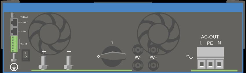
2.5 Interfacing
Bluetooth
VE.Direct
VE.Can
User I/O connector:
Aux 1, 2 input
Programmable relay
Battery Vsense
Battery Tsense
Remote H/L on off *
* Remote L functions as ‘allow to charge’ in case lithium battery is selected and remote H functions as ‘allow to discharge’. Use
miniBMS for the inverter RS with Victron lithium batteries.
2.6 Battery charger
The batteries are charged by solar energy using the built-in MPPT solar controller. It can also be charged by a PV grid inverter
connected to the AC out. In this case the battery will be charged to ~98%. The built-in MPPT has a power limit of 4000W. So the
maximum charging current for a 50V battery will be 80A. If an additional PV grid inverter is connected (max 5000W) the maximum total
charging current is limited to 100A. The maximum charging current of 100A is reduced if battery voltage goes above 60V. A custom
maximum charge current value can also be defined by the installer in VictronConnect.
The charger algorithm is the same as for the BlueSolar MPPT solar controllers. This provides built-in battery preset parameters, and
allows for expert mode to define additional charging parameters. Please see the MPPT section of the VictronConnect manual for
additional explanation of these charging features.
23.INSTALLATION
EN
3.1 Location of the inverter
For best operating results, the inverter should be placed on a flat surface. To
ensure a trouble free operation of the inverter, it must be used in locations that
NL
meet the following requirements:
a) Avoid any contact with water. Do not expose the inverter to rain or
moisture.
FR
b) Do not place the unit in direct sunlight. Ambient air temperature should
be between -20°C and 40°C (humidity < 95% non-condensing).
c) Do not obstruct the airflow around the inverter. Leave at least 30
DE
centimeters clearance above and below the inverter.
When the inverter is running too hot, it will shut down. When the inverter has
reached a safe temperature level the unit will automatically restart again.
SE
CZ
This product contains potentially dangerous voltages. It should only be installed
under the supervision of a suitable qualified installer with the appropriate training,
and subject to local requirements. Please contact Victron Energy for further
information or necessary training.
Appendix
Excessively high ambient temperature will result in the following:
• Reduced service life.
• Reduced charging current.
• Reduced peak capacity, or shutdown of the inverter.
Never position the appliance directly above lead-acid batteries.
The Inverter RS is suitable for wall mounting. For mounting purposes, a hook and
two holes are provided at the back of the casing. The device must be fitted
vertically for optimal cooling.
For safety purposes, this product should be installed in a heat-resistant
environment. You should prevent the presence of e.g. chemicals, synthetic
components, curtains or other textiles, etc., in the immediate vicinity.
Try and keep the distance between the product and the battery to a minimum in order to minimise cable voltage losses
3.2 Connection to the battery
In order to utilize the full capacity of the product, batteries with sufficient capacity and battery cables with sufficient cross section should
be used. See table:
min unit
Battery capacity Pb 400 Ah
Battery capacity Lithium 100 Ah
Recommended DC fuse 150 A
Minimum cross section (mm2) per + 0–2m 35 mm2
and - connection terminal 2–5m 70 mm2
Use a torque wrench with insulated box spanner in order to avoid
shorting the battery.
Maximum torque: 14 Nm
Avoid shorting the battery cables.
• Undo the two screws at the bottom of the enclosure and remove the service panel.
• Connect the battery cables.
• Tighten the nuts well for minimal contact resistance.
3.3 Wire size for connecting the inverter chassis to ground
The earth conductor from the earth lug on the chassis to ground should have at least half the cross-section of the conductors used for
the battery connection.
33.4 Connection to the load
Never connect the output of the inverter to another AC supply, such as a household AC wall outlet or AC wave forming petrol generator.
Wave synchronising PV solar inverters can be connected to the AC output, see section on Frequency Shift Function for more
information.
The Inverter RS is a safety class I product (supplied with a ground terminal
for safety purposes). Its AC output terminals and/or grounding point on
the outside of the product must be provided with an uninterruptible
grounding point for safety purposes.
The Inverter RS is provided with a ground relay that automatically
connects the Neutral output to the chassis. This ensures the correct
operation of the internal earth leakage switch and an earth leakage circuit
breaker that is connected to the output.
─ In a fixed installation, an uninterruptable grounding can be secured by
means of the grounding wire of the AC input. Otherwise the casing
must be grounded.
─ In a mobile installation (for example, with a shore current plug),
interrupting the shore connection will simultaneously disconnect the
grounding connection. In that case, the casing must be connected to
the chassis (of the vehicle) or to the hull or grounding plate (of the
boat).
Torque: 2 Nm
3.5 VE.Direct
Used to connect a PC/laptop to configure the inverter.
3.6 VE.Can
Used to connect to a GX Device.
3.7 Bluetooth
Used to connect to the device via VictronConnect for configuration.
3.8 User I/O
3.8.1 Remote on/off connector
The remote on/off has two terminals: Remote L and Remote H. A remote on/off switch or relay contact can be connected between L and
H. Alternatively, terminal H can be switched to battery plus, or terminal L can be switched to battery minus.
Special case for Victron lithium batteries in combination with the miniBMS. When Lithium is selected in the software, the remote on/off is
changed, and that physical interface instead becomes the connection point for the allow-to-charge and allow-to-discharge wires. The
remote H input is the connection point for the allow-to-discharge control wire and must to be connected to the Load output of the
miniBMS. The remote L input is the connection point for the allow-to-charge control wire and must be connected to the Charger output
of the miniBMS. Remote on/off function is now taken over by the miniBMS.
3.8.2 Programmable relay
Programmable relay which can be set for general alarm, DC under voltage or genset start/stop function. DC rating: 4A up to 35VDC and
1A up to 70VDC
3.8.3 Voltage sense
For compensating possible cable losses during charging, two sense wires can be connected directly to the battery or to the positive and
negative distribution points. Use wire with a cross-section of 0,75mm².
During battery charging, the inverter will compensate the voltage drop over the DC cables up to a maximum of 1 Volt (i.e. 1V over the
positive connection and 1V over the negative connection). If the voltage drop threatens to become larger than 1V, the charging current
is limited in such a way that the voltage drop remains limited to 1V.
3.8.4 Temperature sensor
For temperature-compensated charging, the temperature sensor (supplied with the inverter) can be connected. The sensor is isolated
and must be fitted to the negative terminal of the battery. The temperature sensor can also be used for low temperature cut-off when
charging lithium batteries (configured in VictronConnect).
3.8.5 Programmable analog/digital input ports
The product is equipped with 2 analog/digital input ports. These ports can be configured in VictronConnect.
44. OPERATION
EN
4.1 Protections and automatic restarts
4.1.1 Overload
Some loads like motors or pumps draw large inrush currents during start-up. In such circumstances, it is possible that the start-up
NL
current exceeds the over current limit of the inverter. In this case the output voltage will quickly decrease to limit the output current of the
inverter. If the over current limit is continuously exceeded, the inverter will shut down for 30 seconds and then automatically restart.
After three restarts followed by overload within 30 seconds of restarting, the inverter will shut down and remain off. To restart normal
operation, disconnect the load, Switch Off the inverter, then switch it On.
FR
4.1.2 Low battery voltage thresholds (adjustable in VictronConnect)
The inverter will shut down when the DC input voltage drops below the low battery shutdown level. After a minimum shutdown time of
30 seconds, the inverter will restart if the voltage has risen above the low battery restart level.
DE
After three shut down and restarts, followed by a low battery shutdown within 30 seconds of restarting, the inverter will shut down and
stop retrying based on the low battery restart level. To override this and restart the inverter, switch it Off, and then On, and limit loads to
enable recharging of the battery with solar energy.
SE
The solar MPPT will continue to recharge the battery even when the inverter has shut down due to low battery voltage.
If the inverter has shut down 4 times, it will again attempt to switch itself back on as soon as the DC voltage stays above the Charge
Detect level for 30 seconds.
See the Technical Data table for default low battery shut down, restart and charge detect levels. They can be adjusted with
CZ
VictronConnect (computer or app).
Additionally another external MPPT or battery charger can also be used to recharge the battery to reach the Restart Voltage or Charge
Detect voltage level.
Appendix
!!! If using the allow to charge signal functionality, it must remain above the minimum voltage, so if the battery is completely dead it will
not allow charging to start. In this case, you can temporarily disable this function in VictronConnect to allow charging to resume, then
enable it again.
See the Technical Data table for default low battery shut down and restart levels. They can be changed with VictronConnect (computer
or app).
Alternatively Dynamic Cut-off can be implemented, see https://www.victronenergy.com/live/ve.direct:phoenix-inverters-dynamic-cutoff
4.1.3 High battery voltage
Reduce DC input voltage and/or check for a faulty battery- or solar-charger in the system. After shutting down due to a high battery
voltage, the inverter will first wait 30 seconds and then retry operation as soon as the battery voltage has dropped to acceptable level.
4.1.4 High temperature
A high ambient temperature or enduring high load may result in shut down to over temperature. The inverter will restart after 30
seconds. The inverter will continue to try and resume operation, and will not stay off after multiple retries. Reduce load and/or move
inverter to better ventilated area.
4.2 Device display
The inverter has an LCD screen that displays operational information.
Inverter:
Inverter state, Power output, Frequency and AC Voltage
Battery:
Battery Power (charging shows positive number, discharging shows negative number), Current, DC voltage, Temperature (*),
State-of-charge (*) and Time-to-go (*). Battery state (e.g. discharging, bulk, absorption, float, etc).
(*) These items are only visible if the data is available.
Solar:
Solar Power, Voltage and Current, kWh daily and total Yield.
5In the top right of the display are other system information icons.
Communicating on any interface (e.g., Bluetooth, VE.Can, etc.)
Bluetooth Enabled, Icon colour changes when connected
MPPT Active
(Blinking) Error or Warning
Inverter Active
Battery, fill corresponds with voltage, blinks when empty
5. TROUBLESHOOTING
Check the Victron website for error codes and troubleshooting: https://www.victronenergy.com/live/mppt-error-codes
66. TECHNICAL SPECIFICATIONS
EN
48/6000
Parallel and 3-phase operation no
Maximum PV input power 4000W
Maximum DC charging power 4000W
NL
INVERTER
DC Input voltage range 38 – 64V
Output voltage: 230 VAC ± 2%
Output
Frequency: 50 Hz ± 0,1% (1)
Continuous output power at 25°C Increases linearly from 4800W at 46 VDC to 5300W at 52 VDC
FR
Continuous output power at 40°C 4500W
Continuous output power at 65°C 3300W
Peak power 9kW for 3 seconds
Short-circuit output current 50A
DE
96.5% at 1 kW load
Maximum efficiency
94% at 5 kW load
Zero load power 20W
Low battery shutdown 37.2 V (adjustable)
SE
Low battery restart 43.6 V (adjustable)
SOLAR
Maximum DC voltage 450V
Nominal DC voltage 300V
CZ
Start-up voltage 120V
MPPT voltage range 80 – 400V
DC input current limit 18A
Maximum DC input current 20A
Appendix
Earth leakage trip level 30 mA
Isolation fail level
100 kΩ
(detection before start-up)
CHARGER
Charge voltage 'absorption' (V DC) 57.6V
Charge voltage 'float' (V DC) 55.2V
Maximum charge current 100A
Battery temperature sensor Yes
Battery voltage sense Yes
GENERAL
Auxiliary output No
Programmable relay (3) Yes
Protection (2) a-g
VE.Direct port and VE.Can port Yes
General purpose analog/digital in port Yes, 2x
Remote on-off Yes
Operating temperature range -40 to +65°C (fan assisted cooling)
Humidity (non-condensing) max 95%
ENCLOSURE
Material & Colour steel, blue RAL 5012
Protection category IP22
Battery-connection Two M8 bolts
PV Connection 2 positive & 2 negative MC4
230 V AC-connection Screw terminals 13 mm² (6 AWG)
Weight 11 kg
Dimensions (hxwxd) 425 x 440 x 125 mm
STANDARDS
EN-IEC 60335-1, EN-IEC 60335-2-29,
Safety
EN-IEC 62109-1, EN-IEC 62109-2
EN 55014-1, EN 55014-2
Emission, Immunity EN-IEC 61000-3-2, EN-IEC 61000-3-3
IEC 61000-6-1, IEC 61000-6-2, IEC 61000-6-3
1) Can be adjusted to 60 Hz
2) Protection key:
a) output short circuit
b) overload
c) battery voltage too high
d) battery voltage too low
e) temperature too high
f) 230 VAC on inverter output
g) Solar earth leakage
3) Programmable relay which can be set for general alarm, DC under voltage or genset start/stop function, including minimum closed time and
relay-off delay. DC rating: 4A up to 35VDC and 1A up to 70VDC
71. VEILIGHEIDSAANWIJZINGEN
EN
WAARSCHUWING: GEVAAR VOOR ELEKTRISCHE SCHOK
Het product wordt in combinatie met een permanente energiebron (accu) gebruikt. Ingangs- en/of uitgangsklemmen kunnen nog steeds
NL
gevaarlijk onder stroom staan, zelfs als de apparatuur is uitgeschakeld. Ontkoppel steeds de accu, gelijkstroom-zonnecelisolator,
wisselstroomuitvoer en wacht minstens 5 minuten alvorens onderhoud uit te voeren of het product te repareren.
RISICO OP LETSEL OF OVERLIJDEN
FR
De internen dragen een 400-500 V gelijkstroomvoltage, zelfs wanneer de inverter uitgeschakeld is! Het product is niet uitgerust met
interne onderdelen die door de gebruiker kunnen worden onderhouden. De voorplaat niet verwijderen of bedien het product niet als er
panelen zijn verwijderd. Alle onderhoudswerkzaamheden moeten door gekwalificeerd personeel worden uitgevoerd.
DE
Lees de installatieinstructies in de installatiehandleiding vóór het installeren van het materiaal.
Dit is een product van Veiligheidsklasse I (geleverd met een beschermende aardingsterminal). Het chassis moet worden geaard. Een
aardingspunt bevindt zich aan de buitenzijde van het product. Wanneer het waarschijnlijk is dat de aardbeveiliging is beschadigd, moet
het product worden uitgeschakeld en beveiligd tegen onbedoeld gebruik; gelieve contact op te nemen met gekwalificeerd
SE
onderhoudspersoneel.
Isolatie en bescherming aardingsstoringen
De wisselstroomuitvoer wordt geïsoleerd van de gelijkstroominvoer van de accu. De gelijkstroom PV zonnecelinvoeren worden niet
CZ
geïsoleerd van de wisselstroomuitvoer. De neutraal is verbonden met het chassis via een intern aardingsrelais wanneer de inverter
ingeschakeld is. Een stroombreker voor interne aardingslekken beschermt de zonnecelinvoer. Wanneer een aardingslek ontdekt wordt
bij zonnepanelen naar aarding stopt de inverter met werken. Merk op dat een echte neutraal en aarding van het chassis nodig zijn om te
zorgen voor een correcte werking van de interne en externe stroombreker van aardingslek.
Appendix
Omgeving
Zorg ervoor dat de apparatuur wordt gebruikt onder de juiste omgevingsomstandigheden.
Het product nooit bedienen in een natte of stoffige omgeving.
Het product nooit gebruiken op plaatsen waar gas- of stofexplosies kunnen optreden.
Zorg ervoor dat er voldoende vrije ruimte (30 cm) is voor ventilatie boven en onder het product en controleer dat de ventilatiegaten niet
geblokkeerd zijn.
Dit toestel is niet bedoeld voor gebruik door personen (inclusief kinderen) met beperkte fysieke, zintuiglijke of mentale mogelijkheden, of
gebrek aan ervaring en kennis, tenzij ze toezicht krijgen bij of instructies krijgen met betrekking tot het gebruik van het toestel van een
persoon die verantwoordelijk is voor hun veiligheid.
Er moet toezicht op kinderen gehouden worden om ervoor te zorgen dat ze niet met het toestel spelen.
12. BESCHRIJVING
Volledig configureerbaar
• Laag accuvoltage alarm ontkoppelings- en herinstellingsniveaus
• Laag accuvoltage afsluitings- en herstartniveaus, of Dynamische afsluiting
• Uitvoervoltage 210 - 245 V
• Frequentie 50 Hz of 60 Hz
2.1 Hoge efficiëntie
De algemene maximale efficiëntie van de Inverter RS bedraagt meer dan 96%.
De inverter is beveiligd tegen kortsluitingen en beschermd tegen oververhitting, hetzij door overbelasting of hoge
omgevingstemperatuur.
2.2 Hoog voltage MPPT zonne-energieregelaar
Twee snoeren kunnen verbonden worden met de invoeren. Beiden zijn in parallelschakeling bedraad met een tracker, bijgevolg moeten
de twee snoeren gelijk in aantal van zonnepanelen en type zijn. De totale toegestane invoerstroom is door het toestel beperkt tot 18 A.
! Verbind PV niet met een mogelijke stroom die groter is dan 20 A daar dit het toestel kan beschadigen.
Wanneer de MPPT overschakelt naar druppellaadstadium vermindert het het accuvoltage door het PV-voltage te verhogen (de totale
zonne-energieuitvoer verminderend). Zodat dit systeem kan werken, mag het maximale open stroomvoltage van de PV-serie niet hoger
zijn dan 8-maal het minimale accuvoltage bij druppellaad, tot een absoluut maximum van 450 V. Het overschrijden van de begrenzingen
van dit open stroom PV-voltage is verboden en zal leiden naar systeemuitschakelingen en schade aan het toestel.
Voorbeeld PV-configuraties
Paneeltype Voc Vmpp Isc Impp Aant Max. Ptot
al Snoervoltag
pan e
elen
Ja zonne-energie 39,85 V 32,26 V 9,75 A 9,3 A 2x7 279 V 4200 W
300 W (60Cellen)
Panasonic HIT 70,9 V 59,2 V 5,94 A 5,5 A 2x6 425 V 3900 W
N325K (96Cellen)
SunPower X22 360 69,5 V 59,1 V 6,48 A 6,09 A 2x6 417 V 4320 W
W (96 Cellen)
Victron 330 W (70 44,72 V 37,3 V 9,57 A 8,86 A 2x6 268 V 3960 W
cellen)
2.3 Frequentieverschuivingsfunctie
Wanneer externe PV-inverters met de uitvoer van de inverter verbonden zijn, wordt overmatige zonne-energie gebruikt om de accu's
opnieuw op te laden, net zoals met de interne MPPT zonne-energieregelaar. Eens het absorptievoltage van de accu bereikt werd, zal
de laadstroom verminderen door de uitvoerfrequentie hoger te verschuiven. Deze functie wordt gebruikt voor bescherming tegen
overladen en zonne-energiehulp. Voor veiligheidsredenen staat het niet toe de accu volledig op te laden tot 100% SoC.
2.4 Hoog piekvermogen
De inverter kan gedurende korte tijd 50 Amp wisselstroom of 9000 W leveren.
2.5 Interfacen
Bluetooth
VE.Direct
VE.Can
Gebruiker I/O connector:
Aux 1, 2 invoer
Programmeerbaar relais
Accu Vsense
Accu Tsense
H/L aan uit op afstand *
* L-functies op afstand zoals ‘toestaan op te laden’ wanneer lithium-accu geselecteerd wordt H-functies op afstand zoals ‘toestaan te
ontladen’. Gebruik miniBMS voor de inverter RS met Victron lithium-accu's.
2.6 Acculader
De accu's worden met zonne-energie geladen via de ingebouwde MPPT zonne-energieregelaar. Het kan ook geladen worden door een
PV-netwerkinverter, verbonden met de wisselstroom uit. In dit geval zal de accu opgeladen worden tot ~ 98%. De ingebouwde MPPT
heeft een vermogensbeperking van 4000 W. Dus de maximale laadstroom voor een 50 V-accu zal 80 A zijn. Wanneer een extra PV-
netwerkinverter verbonden wordt (max. 5000 W) i de maximale laadstroom beperkt tot 100 A. De maximale laadstroom van 100 A is
beperkt wanneer het accuvoltage boven 60 V gaat. Een gewone maximale laadstroomwaarde kan ook door de installateur bepaald
worden in VictronConnect.
Het laadalgoritme is hetzelfde als voor de BlueSolar MPPT zonne-energieregelaars. Dit levert ingebouwde vooraf ingestelde
parameters van de accu en staat expertmodus toe om extra laadparameters te bepalen. Bekijk het MPPT-hoofdstuk van de
VictronConnect-handleiding voor extra uitleg over deze laadfuncties.
23.INSTALLATIE
EN
3.1 Locatie van de inverter
Voor de beste werkingsresultaten moet de inverter op een vlak oppervlak geplaatst
worden. Om te zorgen voor een probleemloze werking van de inverter moet het
NL
gebruikt worden op locaties die tegemoetkomen aan de volgende vereisten:
c) Vermijd elk contact met water. Stel de inverter niet bloot aan regen of
vocht.
FR
d) Plaats het toestel niet in rechtstreeks zonlicht. Luchttemperatuur van de
omgeving moet tussen -20°C en 40°C liggen (luchtvochtigheid < 95%
niet-condenserend).
DE
d) Blokkeer de luchtstroom rond de inverter niet. Laat minstens een vrije
ruimte van 30 centimeter boven en onder de inverter.
Wanneer de inverter te heet draait, zal deze stopgezet worden. Wanneer de
inverter een veilig temperatuurniveau bereikt heeft, zal het toestel automatisch
SE
terug opstarten.
CZ
Dit product bevat potentieel gevaarlijke spanningen. Het dient alleen worden
geïnstalleerd onder toezicht van een geschikte gekwalificeerde installateur met de
juiste opleiding en in overeenkomst met de lokale vereisten. Contacteer Victron
Energy voor meer informatie of de nodige opleidingen.
Appendix
Een hoge omgevingstemperatuur resulteert in het volgende:
• Kortere levensduur.
• Gereduceerde laadstroom.
• Verminderd piekvermogen of uitschakelen van de omvormer.
Plaats de machine nooit rechtstreeks boven loodzwavelzuuraccu's.
De Inverter RS is geschikt voor muurmontage. Voor montagedoeleinden worden
een haak en twee gaten voorzien aan de achterzijde van het omhulsel. Het toestel
moet verticaal gemonteerd worden voor optimale verkoeling.
Voor veiligheidsdoeleinden moet dit product in een hittebestendige omgeving
worden geïnstalleerd. Vermijd de aanwezigheid van bijv. chemicaliën, synthetische
componenten, gordijnen of ander textiel enz.
Tracht de afstand tussen het product en de accu tot een minimum te beperken om verlies aan kabelvoltage te minimaliseren
3.2 Verbinding met de accu
Teneinde de volledige capaciteit van het product volledig te benutten, moeten de accu's met voldoende capaciteit en accukabels met
een geschikte doorsnede worden gebruikt. Zie tabel:
toes
min.
tel
Accucapaciteit Pb 400 Ah
Accucapaciteit Lithium 100 Ah
Aanbevolen gelijkstroomzekering 150 A
Minimale dwarsdoorsnede (mm2) per 0–2m 35 mm2
+ en - verbindingsklem 2–5m 70 mm2
Gebruik een momentsleutel met geïsoleerde steeksleutel om te
voorkomen dat de accu kortsluit.
Maximum koppel: 14 Nm
Vermijd het kortsluiten van de accukabels.
• Draai de twee schroeven aan de onderzijde van de behuizing en verwijder het bedieningspaneel.
• Sluit de accukabels aan.
• Draai de moeren goed vast voor minimale contactweerstand.
33.3 Draadomvang voor het verbinden van inverterchassis aan aarding
De aardingsgeleider van de aardingsaansluiting op het chassis tot aarding moet minstens de helft hebben van de dwarsdoorsnede van
de geleiders, gebruikt voor de batterijverbinding.
3.4 Verbinding met de belasting
Verbind nooit de uitvoer van de inverter met een andere wisselstroomtoevoer, zoals een huishoudelijke wisselstroom muuruitvoer of
wisselstroomgolfvormende benzinegenerator. Golfsynchroniserende PV zonne-energieinverters kunnen met de wisselstroomuitvoer
verbonden worden, zie hoofdstuk over Frequentie Verplaatsingsfunctie voor meer informatie.
De Inverter RS is een product van veiligheidsklasse I (geleverd met een
aardingsklem voor veiligheidsdoeleinden). Diens
wisselstroomuitvoerklemmen en/of aardingspunt aan de buitenkant
van het product moeten geleverd worden met een niet-
onderbreekbaar aardingspunt voor veiligheidsdoeleinden.
De Inverter RS wordt geleverd met een aardingsrelais dat automatisch de
Neutrale uitvoer verbindt met het chassis. Dit zorgt voor de correcte
werking van de interne aardingslekschakelaar en een stroombreker van
aardingslek die verbonden is met de uitvoer.
─ In een vaste installatie kan een onderbrekingsloze aarding worden
vastgezet door middel van de aardingsdraad van de AC-ingang.
Anders moet de behuizing worden geaard.
─ Bij een mobiele installatie (bijvoorbeeld met een walstroomstekker)
zal het onderbreken van de walverbinding tegelijkertijd de
aardingsverbinding verbreken. In dat geval moet de behuizing worden
aangesloten op het chassis (van het voertuig) of op de romp of
aardingsplaat (van de boot).
Torsie. 2 Nm
3.5 VE.Direct
Gebruikt om een PC/laptop te verbinden om de inverter te configureren.
3.6 VE.Can
Gebruikt om te verbinden met een GX-toestel.
3.7 Bluetooth
Gebruikt om verbinding te maken met het toestel via VictronConnect voor configuratie.
3.8 Gebruiker I/O
3.8.1 Aan/uit-connector op afstand
De aan/uit op afstand heeft twee klemmen: L op afstand en H op afstand. Een aan/uit-schakelaar op afstand of relaiscontact kan
verbonden worden tussen L en H. Alternatief kan klem H omgeschakeld worden naar batterij plus of klem L kan omgeschakeld worden
naar batterij minus.
Speciaal omhulsel voor Victron lithium accu's in combinatie met de miniBMS. Wanneer Lithium in de software geselecteerd wordt, wordt
de aan/uit op afstand gewijzigd en dat in de plaats ervan fysieke interface het verbindingspunt wordt voor de toestaan-tot-opladen en
toestaan-tot-ontladen kabels. De H-invoer op afstand is het verbindingspunt voor de regelingskabel voor toestaan-tot-ontladen en moet
verbonden worden met de Belastinguitvoer van de miniBMS. De L-invoer op afstand is het verbindingspunt voor de regelingskabel voor
toestaan-tot-laden en moet verbonden worden met de Laderuitvoer van de miniBMS.Aan/uit-functie op afstand wordt nu overgenomen
door de miniBMS.
3.8.2 Programmeerbare relais
Programmeerbare relais die ingesteld kan worden voor algemeen alarm, gelijkstroom onder voltage of start/stop-functie van
stroomaggregaat. Gelijkstroom-waarde: 4 A tot 35 VDC en 1 A tot 70 VDC
3.8.3 Voltage sense
Voor het compenseren van mogelijk kabelverlies tijdens het opladen, kunnen twee sensedraden rechtstreeks met de accu verbonden
worden of met de positieve en negatieve verdeelpunten. Gebruik draad met een doorsnede van 0,75mm².
Tijdens het opladen van de accu zal de inverter het voltageverlies over de gelijkstroomkabels compenseren tot een maximum van 1 Volt
(i.e. 1 V over de positieve verbinding en 1 V over de negatieve verbinding). Als het voltageverlies groter dreigt te worden dan 1 V, wordt
de laadstroom zodanig beperkt dat het voltageverlies beperkt blijft tot 1 V.
3.8.4 Temperatuursensor
Voor temperatuur-gecompenseerd opladen kan de temperatuursensor (geleverd met de inverter) verbonden worden. De sensor is
geïsoleerd en moet op de negatieve pool van de accu worden aangebracht. De temperatuursensor kan ook gebruikt worden voor lage
temperatuur-afsluiting bij het opladen van lithium accu's (geconfigureerd in VictronConnect).
3.8.5 Programmeerbare analoge/digitale invoerpoorten
Het product is uitgerust met 2 analoge/digitale invoerpoorten. Deze poorten kunnen geconfigureerd worden in VictronConnect.
44. BEDIENING
EN
4.1 Beveiligingen en automatische herstarten
4.1.1 Overbelasting
Sommige belastingen zoals motoren of pompen trekken grote toevloedstromen tijdens de opstart. In dergelijke omstandigheden is het
mogelijk dat de opstartstroom de overstroombeperking van de inverter overschrijdt. In dit geval zal het uitvoervoltage snel afnemen om
de uitvoerstroom van de inverter te begrenzen. Wanneer de overstroombeperking voortdurend overschreden wordt, zal de inverter
NL
gedurende 30 seconden uitgeschakeld worden en dan automatisch opnieuw opstarten.
Na drie herstarten gevolgd door overbelasting binnen 30 seconden van herstarten, zal de inverter uitgeschakeld worden en uit blijven.
Om normale bediening opnieuw op te starten, ontkoppel de belasting, schakel de inverter uit, schakel dan terug in.
4.1.2 Lage accuvoltagedrempels (aanpasbaar in VictronConnect)
FR
De inverter wordt uitgeschakeld als de gelijkstroom-invoerspanning daalt tot onder het uitschakelingsniveau van de lage accu. Na een
minimale afsluittijd van 30 seconden zal de inverter opnieuw opstarten wanneer het voltage gestegen is tot boven het herstartniveau
van de lage accu.
Na drie uitschakelingen en herstarten, gevolgd door een lage accu-uitschakeling binnen 30 seconden van herstarten, zal de inverter
DE
uitschakelen en stoppen met opnieuw proberen, gebaseerd op het herstartniveau van de lage accu. Om dit te overschrijven en de
inverter te herstarten, schakel het Uit, en dan Aan en beperk belastingen om het opnieuw opladen van de accu met zonne-energie in te
schakelen.
De zonne-energie MPPT zal de accu blijven herladen zelfs wanneer de inverter uitgeschakeld werd vanwege en laag accuvoltage.
SE
Wanneer de inverter viermaal uitgeschakeld werd, zal het zichzelf opnieuw trachten in te schakelen zodra het gelijkstroomvoltage boven
het Laaddetectieniveau blijft gedurende 30 seconden.
Zie de Technische Gegevenstabel voor standaard lage accusluiting, -herstart- en laaddetectieniveaus. Ze kunnen aangepast worden
met VictronConnect (computer of app).
CZ
Bijkomend kan een andere externe MPPT of acculader ook gebruikt worden om de accu te herladen om het Herstartvoltage of
Laaddetectie voltageniveau te bereiken.
!!! Bij gebruik van de toestaan om te laden signaalfunctionaliteit moet het boven het minimum voltage blijven, dus wanneer de accu
volledig leeg is, zal het opladen om te starten niet toestaan. In dit geval kan u tijdelijk deze functie in VictronConnect uitschakelen om
Appendix
opladen toe te staan te hervatten, schakel het dan opnieuw in.
Zie de Technische Gegevenstabel voor standaard lage accusluiting en herstartniveaus. Ze kunnen gewijzigd worden met
VictronConnect (computer of app).
Alternatief kan Dynamisch afsluiten geïmplementeerd worden, zie https://www.victronenergy.com/live/ve.direct:phoenix-inverters-
dynamic-cutoff
4.1.3 Hoog accuvoltage
Verlaag de gelijkstroom-invoerspanning en/of controleer op een defecte accu- of zonne-lader in het systeem. Na het uitschakelen
vanwege een hoge accuspanning, wacht de inverter eerst 30 seconden en probeert te herstarten zodra de accuspanning is gedaald tot
een aanvaardbaar niveau.
4.1.4 Hoge temperatuur
Een hoge omgevingstemperatuur of een blijvende hoge belasting kan ertoe leiden dat de temperatuur te hoog wordt. De inverter zal na
30 seconden herstarten. De inverter zal blijven proberen en bediening hervatten, en zal niet uitgeschakeld blijven na meerdere nieuwe
pogingen. Reduceer de belasting en/of verplaats de inverter naar een beter geventileerde ruimte.
4.2 Toestelweergave
De inverter heeft een LCD-scherm dat bedieningsinformatie weergeeft.
Inverter:
Inverterstatus, Vermogenuitvoer, Frequentie en wisselstroomvoltage
Accu:
Accuvermogen (laden toont positief nummer, ontladen toont negatief nummer), Stroom, gelijkstroomvoltage, Temperatuur (*),
Oplaadstatus (*) en Resterende tijd (*). Accustatus (bv. ontladen, bulk, absorptie, druppelladen, enz.).
(*) Deze items zijn enkel zichtbaar wanneer de gegevens beschikbaar zijn.
Zonne-energie:
Zonne-energie, Voltage en Stroom, kWh dagelijks en totaal Rendement.
5Rechts bovenaan in het beeldscherm staan andere systeeminformatie-iconen.
Communiceren op elke interface (bv., Bluetooth, VE.Can, enz.)
Bluetooth ingeschakeld, Icoonkleur wijzigt wanneer verbonden
MPPT Actief
(knipperend) Foutmelding of Waarschuwing
Inverter Actief
Accu, vulling stemt overeen met voltage, knippert wanneer leeg
5. PROBLEEMOPLOSSING
Controleer de Victron Website voor foutmeldingscodes en probleemoplossingen: https://www.victronenergy.com/live/mppt-error-codes
66. TECHNISCHE SPECIFICATIES
EN
48/6000
Parallelle en 3-fasige bediening nee
Maximaal PV-invoervermogen 4000 W
Maximaal gelijkstroom-laadvermogen 4000 W
NL
INVERTER
Gelijkstroominvoer voltagebereik 38 – 64 V
Uitvoerspanning: 230 VAC ± 2%
Uitvoer
Frequentie: 50 Hz ± 0,1% (1)
Voortdurend uitvoervermogen aan 25°C Verhoogt lineair van 4800 W bij 46 VDC tot 5300 W bij 52 VDC
FR
Voortdurend uitvoervermogen aan 40°C 4500 W
Voortdurend uitvoervermogen aan 65°C 3300 W
Piekvermogen 9 kW voor 3 seconden
Uitvoerstroom kortsluiting 50 A
DE
96,5% bij 1 kW belasting
Maximale efficiëntie
94% bij 5 kW belasting
Nul belastingsvermogen 20 W
Lage accu uitschakeling 37,2 V (aanpasbaar)
SE
Lage accuherstart 43,6 V (aanpasbaar)
ZONNE-ENERGIE
Maximaal gelijkstroomvoltage 450 V
Nominaal gelijkstroomvoltage 300 V
CZ
Opstartvoltage 120 V
MPPT voltagebereik 80 – 400 V
Stroombegrenzing gelijkstroominvoer 18 A
Maximale stroom gelijkstroominvoer 20 A
Appendix
Ontkoppelingsniveau aardingslek 30 mA
Isolatiestoringsniveau
100 kΩ
(detectie vóór opstart)
LADER
Laadvoltage 'absorptie' (V DC) 57,6 V
Laadvoltage 'druppelllaad' (V DC) 55,2 V
Maximale laadstroom 100 A
Accutemperatuursensor Ja
Accuvoltagesense Ja
ALGEMEEN
Hulpuitvoer Nee
Programmeerbaar relais (3) Ja
Beveiliging (2) a-g
VE.Direct-poort en VE.Can-poort Ja
Algemeen doel analoog/digitaal in poort Ja, 2x
Op afstand aan-uit Ja
Bereik bedieningstemperatuur -40 tot +65°C (door ventilator geassisteerde koeling)
Vochtigheid (niet-condenserend) max. 95%
BEHUIZING
Materiaal & Kleur staal, blauw RAL 5012
Beschermingscategorie IP22
Accu-aansluiting Twee M8-bouten
PV-aansluiting 2 positieve & 2 negatieve MC4
230 V wisselstroomverbinding Schroefklemmen 13 mm2 (6 AWG)
Gewicht 11 kg
Afmetingen (hxbxd) 425 x 440 x 125 mm
NORMEN
EN-IEC 60335-1, EN-IEC 60335-2-29,
Veiligheid
EN-IEC 62109-1, EN-IEC 62109-2
EN 55014-1, EN 55014-2
Emissie, immuniteit EN-IEC 61000-3-2, EN-IEC 61000-3-3
IEC 61000-6-1, IEC 61000-6-2, IEC 61000-6-3
1) Kan aangepast worden naar 60 Hz
2) Beveiligingssleutel:
a) kortsluiting bij uitvoer
b) overbelasting
c) accuvoltage te hoog
d) accuvoltage te laag
e) temperatuur te hoog
f) 230 VAC op inverteruitvoer
g) Aardingslek zonne-energie
3) Programmeerbare relais die ingesteld kan worden voor algemeen alarm, gelijkstroom onder voltage of start/stop-functie van stroomaggregaat, inclusief
minimaal gesloten tijd en relais-uit vertraging. Gelijkstroom-waarde: 4 A tot 35 VDC en 1 A tot 70 VDC
71. CONSIGNES DE SÉCURITÉ
EN
ATTENTION : RISQUE D'ÉLECTROCUTION
L’appareil est utilisé conjointement avec une source d’énergie permanente (batterie). Même lorsque l'appareil est hors tension, une
tension dangereuse peut être présente sur les bornes d'entrée et de sortie. Avant d'effectuer la maintenance ou la réparation du produit,
NL
vous devez toujours déconnecter la batterie, l'isolateur solaire CC, la sortie CA et attendre au moins 5 minutes.
RISQUE DE BLESSURE OU DE MORT
FR
Au niveau interne, une tension de 400-500 VCC est transportée, même si l'onduleur est éteint ! L'appareil ne contient aucun élément
interne pouvant être réparé par l’utilisateur. Ne jamais retirer le panneau frontal et ne jamais mettre l'appareil en service si tous les
panneaux ne sont pas montés. Toute réparation doit être effectuée par du personnel qualifié.
Veuillez lire attentivement les consignes d'installation avant de mettre l'appareil en service.
DE
Cet appareil est un produit de classe de sécurité I (livré avec une borne de mise à la terre de protection). Le châssis doit être mis à la
masse. Un point de mise à la terre est situé à l’extérieur du boîtier de l’appareil Si vous suspectez la protection par prise de terre d’être
endommagée, l’appareil doit être mis hors tension et protégé contre toute mise en service involontaire ; faire appel à du personnel
qualifié.
SE
Isolation et protection contre les défauts de mise à la terre
La sortie CA est isolée par rapport à l'entrée CC de la batterie. Les entrées solaires PV de CC ne sont pas isolées de la sortie CA. La
CZ
connexion neutre est connectée au châssis avec un relais à la terre interne lorsque l'onduleur est allumé. Un interrupteur différentiel
interne protège l'entrée solaire. Si une fuite à la terre est détectée entre les panneaux solaires et le sol, l'onduleur s'arrête. Notez qu'un
vrai neutre et une mise à la masse du châssis sont nécessaires pour garantir le fonctionnement correct d'interrupteurs différentiels
interne et externe.
Appendix
Environnement
Assurez-vous que l'appareil est utilisé dans des conditions d'exploitation appropriées.
Ne jamais l'utiliser dans un environnement humide ou poussiéreux.
Ne pas utiliser l'appareil dans un endroit présentant un risque d'explosion de gaz ou de poussière.
Conservez toujours suffisamment d'espace libre au-dessus et en dessous de l'appareil (30 cm) pour la ventilation et assurez-vous que
les orifices de ventilation ne sont pas obstrués.
Cet appareil n'est pas prévu pour être utilisé par des personnes (dont les enfants) ayant un handicap physique, sensoriel ou mental, ou
un manque d'expérience et de connaissances, sauf si elles se trouvent sous la supervision ou si elles ont reçu des instructions
concernant l'utilisation de l'appareil d'une personne responsable de leur sécurité.
Les enfants doivent être surveillés pour être sûr qu'ils ne jouent pas avec l'appareil.
12. DESCRIPTION
Entièrement configurable
• Niveaux de réinitialisation et de déclenchement de l'alarme en cas de tension de batterie faible.
• Niveaux de tension de redémarrage et de coupure en cas de tension de batterie faible, ou Coupure Dynamique.
• Tension de sortie 210 – 245 V
• Fréquence de sortie 50 Hz ou 60 Hz
2.1 Haute efficacité
L'efficacité maximale totale de l'onduleur RS est supérieure à 96 %.
L'onduleur est protégé contre les courts-circuits et la surchauffe, que ce soit en cas de surcharge ou de température ambiante élevée.
2.2 Contrôleur solaire MPPT de haute tension
Deux files peuvent être connectées aux entrées. Les deux sont branchées en parallèle à un localisateur, c'est pourquoi, les deux files
doivent être égales en nombre et type de panneaux solaires. Le courant d'entrée total permis est limité par l'appareil à 18 A.
! NE PAS connecter l'onduleur PV avec un courant potentiel supérieur à 20 A, car cela pourrait endommager l'appareil.
Lorsque le MPPT commute à l'étape Float, il réduit la tension de la batterie en augmentant la tension PV (ce qui réduit la sortie de
puissance solaire totale). Pour que ce système fonctionne, la tension de circuit ouvert maximale du champ PV ne doit pas être
supérieure de plus de 8 fois à la tension minimale de la batterie en mode Float, avec un maximum absolu de 450 V. Au-dessus de cette
valeur, la limite de tension PV du circuit ouvert est interdite, ce qui causera l'arrêt du système et endommagera l'appareil.
Exemples de configuration PV.
Type de panneaux Voc Vmpp Isc Impp Nbre de Tension Ptot
panneaux de
maxi.
de la
file
JA SOLAR 300 W 39,85 V 32,26 V 9,75 A 9,3 A 2x7 279 V 4 200 W
(60 cellules)
Panasonic HIT 70,9 V 59,2 V 5,94 A 5,5 A 2x6 425 V 3 900 W
N325K (96 cellules)
SunPower X22 69,5 V 59,1 V 6,48 A 6,09 A 2x6 417 V 4 320 W
360 W (96 cellules)
Victron 330 W 44,72 V 37,3 V 9,57 A 8,86 A 2x6 268 V 3 960 W
(70 cellules)
2.3 Fonction d'ajustement de fréquence
Lorsque des onduleurs PV externes sont raccordés à la sortie de l'onduleur, l'excès d'énergie solaire est utilisé pour recharger les
batteries, comme avec le contrôleur solaire MPPT interne. Dès que la tension d'absorption de la batterie est atteinte, le courant de
charge diminuera en augmentant la fréquence de sortie. Cette fonction est utilisée pour protéger la batterie contre des surcharges. Elle
ne permet pas de recharger la batterie à sa pleine charge SoC de 100 % pour des raisons de sécurité.
2.4 Puissance de crête élevée
L'onduleur peut fournir une puissance de 50 Amp CA ou 9 000 W sur une courte période de temps.
2.5 Interfaçage
Bluetooth
VE.Direct
VE.Can
Connecteur E/S d'utilisateur :
Entrée aux. 1, 2
Relais programmable
Sonde de tension de batterie
Sonde de température de batterie
Borne d'allumage/arrêt à distance H/L *
* Fonctions de borne L à distance = « Autorisation de charger » si une batterie au lithium est sélectionnée, et fonctions de borne H à
distance = « Autorisation de décharger ». Utiliser un miniBMS pour l'onduleur RS avec des batteries au lithium Victron.
2.6 Chargeur de batterie
Les batteries sont rechargées par de l'énergie solaire à l'aide du contrôleur solaire MPPT intégré. Elles peuvent également être
rechargées via un onduleur de réseau PV connecté à la sortie CA. Dans ce cas, la batterie sera rechargée à ~98 %. Le MPPT intégré
présente une limite de puissance de 4 000 W. Ainsi, le courant de recharge maximal pour une batterie de 50 V sera de 80 A. Si un
onduleur de réseau PV supplémentaire est branché (5 000 W maxi.), le courant de charge total maximal est limité à 100 A. Le courant
de charge maximal de 100 A est réduit si la tension de batterie dépasse 60 V. Une valeur de courant de charge maximal personnalisée
peut également être définie par l'installateur dans VictronConnect.
L'algorithme de charge est le même que pour les contrôleurs solaires MPPT BlueSolar. Il transmet des paramètres préconfigurés et en
mode expert, il permet de définir des paramètres de charge supplémentaires. Veuillez consulter la section MPPT du manuel
VictronConnect pour davantage d'explications concernant ces fonctions de charge.
23. INSTALLATION
EN
3.1 Emplacement de l'onduleur
Pour de meilleurs résultats d'exploitation, l'onduleur devra être placé sur une
surface plate. Pour garantir un fonctionnement sans problème de l'onduleur, il doit
NL
être utilisé dans des endroits qui répondent aux exigences suivantes :
e) Éviter le contact avec de l'eau. Ne pas exposer l'onduleur à la pluie ou à
la moisissure.
FR
f) Ne pas placer l'unité directement à la lumière du soleil. La température
ambiante devra être comprise entre -20°C et 40 °C (humidité < 95 %
sans condensation).
DE
e) Ne pas obstruer le passage de l'air autour de l'onduleur. Laisser un
espace d'au moins 30 centimètres au-dessus et en dessous de
l'onduleur.
Lorsque l'onduleur fonctionne à une température trop élevée, il s'arrêtera. Dès que
SE
l'onduleur aura atteint un niveau de température sûr, l'unité redémarrera
automatiquement.
CZ
Ce produit présente des tensions potentiellement dangereuses. Il ne doit être
installé que sous la supervision d'un installateur qualifié disposant de la formation
adaptée et conformément aux exigences locales. Veuillez contacter Victron pour
davantage d'information ou pour la formation nécessaire.
Appendix
Une température ambiante trop élevée aura pour conséquences :
• Réduction de la longévité.
• Courant de charge réduit.
• Puissance de crête réduite ou arrêt total de l'onduleur.
Ne jamais placer l'appareil directement au-dessus des batteries au plomb.
L'onduleur RS peut être fixé au mur. À des fins de montage, un crochet et deux
orifices sont disponibles à l'arrière du boîtier. L'appareil doit être installé
verticalement pour un refroidissement optimal.
Pour des raisons de sécurité, cet appareil doit être installé dans un environnement
résistant à la chaleur. Évitez la présence de produits tels que des produits
chimiques, des composants synthétiques, des rideaux ou d'autres textiles, à
proximité de l'appareil.
Conservez une distance minimale entre l'appareil et les batteries afin de réduire les pertes de tension dans les câbles.
3.2 Raccordement à la batterie
Pour bénéficier de la puissance maximale de l'appareil, il est nécessaire d'utiliser des batteries de capacité suffisante et des câbles de
section suffisante. Voir le tableau :
unit
min
é
Capacité batterie Pb 400 Ah
Capacité de la batterie Lithium 100 Ah
Fusible CC recommandé 150 A
Section de câble minimale (mm2) par 0–2m 35 mm2
borne de connexion + et - 2–5m 70 mm2
Utilisez une clé à pipe isolante afin d'éviter de court-circuiter la
batterie.
Moment de force maximal : 14 Nm
Évitez de court-circuiter les câbles de batterie.
• Dévissez les deux vis au bas du boîtier et enlevez le panneau de service.
• Raccordez les câbles de batterie :
• Serrez correctement les boulons pour éviter la résistance au contact.
33.3 Taille des fils pour la mise à la terre du châssis de l'onduleur
Le fil de terre provenant de la cosse de la terre sur le châssis vers le sol devra présenter une section équivalente à au moins la moitié
de celle des conducteurs utilisés pour le raccordement de la batterie.
3.4 Raccordement à la charge
Ne jamais connecter la sortie de l'onduleur à une autre source CA, telle qu'une prise de courant murale CA d'un appareil
électroménager ou d'un générateur à essence formant une onde CA. Des onduleurs solaires PV de synchronisation d'ondes peuvent
être raccordés à la sortie CA. Consultez la section Fonction d'ajustement de la fréquence pour davantage d'information.
Cet onduleur RS est un produit de classe de sûreté I (livré avec une borne
de terre pour des raisons de sécurité). Ses bornes de sortie CA et/ou son
point de mise à la terre sur la partie externe de l'appareil doivent être
fournis avec un point de mise à la terre sans coupure pour des
raisons de sécurité.
L'onduleur RS est équipé d'un relais de mise à la terre qui raccorde
automatiquement la sortie du neutre au châssis. Cela permet le
fonctionnement correct du commutateur de fuite à la terre et d'un
disjoncteur différentiel interne connecté à la sortie.
─ Sur une installation fixe, une mise à la terre sans coupure peut être
sécurisée au moyen du câble de terre de l’entrée CA. Autrement, le
boîtier doit être mis à la masse.
─ Pour les installations mobiles, (par exemple avec une prise de
courant de quai), le fait d’interrompre la connexion de quai va
déconnecter simultanément la connexion de mise à la terre. Dans ce
cas, le boîtier de l'appareil doit être raccordé au châssis (du véhicule),
ou à la plaque de terre ou à la coque (du bateau).
Moment de force : 2 Nm
3.5 VE.Direct
Utilisé pour raccorder un PC/ordinateur portable permettant de configurer l'onduleur.
3.6 VE.Can
Utilisé pour raccorder un appareil GX.
3.7 Bluetooth
Utilisé pour raccorder l'appareil via VictronConnect à des fins de configuration.
3.8 E/S de l'utilisateur
3.8.1 Connecteur d'allumage/arrêt à distance
L'allumage/arrêt à distance du système dispose de deux bornes : Borne L à distance et Borne H à distance. Un interrupteur
d'allumage/arrêt à distance ou un .contact de relais peut être branché entre L et H. Sinon, la borne H peut être commutée à la borne
positive de la batterie, ou la borne L peut être commutée à la borne négative de la batterie.
Cas spécial pour des batteries au lithium Victron avec le miniBMS. Lorsque le type Lithium est sélectionné dans le logiciel, la
fonctionnalité d'allumage/arrêt à distance est modifiée et cette interface physique devient le point de connexion pour « Autorisation de
charger » et « Autorisation de décharger ». L'entrée à distance H est le point de connexion pour le fil de contrôle de « Autorisation de
décharger », et elle doit être connectée à la sortie de la charge du miniBMS. L'entrée à distance L est le point de connexion pour le fil
de contrôle de « Autorisation de charger », et elle doit être connectée à la sortie du chargeur du miniBMS. La fonction d'allumage/arrêt
à distance est à présent prise en charge par le miniBMS.
3.8.2 Relais programmable
Relais programmable pouvant être configuré en alarme générale, de sous-tension CC ou comme fonction de démarrage/arrêt du
générateur Rendement CC : 4 A jusqu'à 35 VCC, 1 A jusqu'à 70 VCC
3.8.3 Sonde de tension
Pour compenser des pertes possibles dans les câbles au cours du processus de charge, une sonde à deux fils peut être raccordée
directement à la batterie ou aux points de distribution positifs ou négatifs. Utilisez des câbles avec une section de 0,75 mm².
Pendant le chargement de la batterie, l'onduleur compensera les chutes de tension des câbles CC à un maximum de 1 Volt (c'est à dire
1 V sur la connexion positive et 1 V sur la connexion négative). S'il y a un risque que les chutes de tension soient plus importantes que
1 V, le courant de charge sera limité de telle manière que la chute de tension restera limitée à 1 V.
3.8.4 Sonde de température
Pour compenser les changements de température lors de la charge, la sonde de température (fournie avec l'onduleur) peut être
connectée. La sonde est isolée et doit être fixée à la borne négative de la batterie. La sonde de température peut également être
utilisée en cas de coupure due à une température basse durant la recharge des batteries au lithium (configuré dans VictronConnect).
3.8.5 Ports programmables d'entrée analogique/numérique
Le produit est équipé de deux ports d'entrée analogique/numérique. Ces ports peuvent être configurés dans VictronConnect.
4You can also read