Investigation of the modular building metal frame nodal connection rotational stiffness
←
→
Page content transcription
If your browser does not render page correctly, please read the page content below
E3S Web of Conferences 281, 01045 (2021)                                 https://doi.org/10.1051/e3sconf/202128101045
CATPID-2021 Part 1

      Investigation of the modular building metal
      frame nodal connection rotational stiffness
      Vyacheslav Shirokov, Oleg Veremeenko, and Vadim Alpatov*
      Samara State Technical University, 443100, Samara, Russia

                    Abstract. The research subject is the rotational stiffness of the modular
                    building metal frame nodal connection. The stiffness of nodal connections
                    has a significant impact on the results of calculating the load-bearing frame
                    of a modular building. It is known that absolutely rigid connections exist
                    only in theory. In practice, each nodal connection has a finite stiffness, as
                    evidenced by numerous studies of the researchers. When designing the real
                    objects, the studies on the stiffness of nodal connections of a certain design
                    should be carried out. As a rule, when designing real objects, there is no
                    time to carry out the research. The designer operates with well-known and
                    reliably proven recommendations. It is important for him to have the
                    ready-made solutions for implementation in design practice. Such
                    solutions can be provided on the basis of preliminary studies of the joints’
                    behavior of the structural elements under load. The article presents a
                    solution to such a problem. The study of the stiffness of the nodal
                    connection with the connected elements parameters variation has been
                    carried out. The purpose of the study is to find the boundaries of design
                    solutions at which the connection can be considered rigid.

      1 Introduction
      The classification of nodal connections is adopted according to Eurocode 3, which sets the
      boundaries for hinged, semi-rigid and rigid nodes. To calculate the initial rotational
      stiffness values, the component finite element method was used (CFEM), implemented in
      IDEA StatiCA. As a result of the study, the rotational stiffness values of fastening the
      crossbars to the columns have been obtained. It has been established that, in the spans
      typical for modular buildings, the nodes with direct adjoining channels to square tube racks
      should be generally classified as semi-rigid and their rotational stiffness should be taken
      into account in the design schemes. For the nodes with an additional rib, the change in the
      attachment rotational stiffness is non-linear.
          Based on the research results, a nomogram for various sections of channels and square
      pipes with minimum rib sizes, at which the crossbar-to-rack connection node should be
      considered rigid, has been built. This nomogram is recommended for use when
      dimensioning stiffeners.

      *   Corresponding author: avu75@mail.ru

© The Authors, published by EDP Sciences. This is an open access article distributed under the terms of the Creative Commons
Attribution License 4.0 (http://creativecommons.org/licenses/by/4.0/).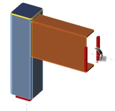
E3S Web of Conferences 281, 01045 (2021)                      https://doi.org/10.1051/e3sconf/202128101045
CATPID-2021 Part 1

          Currently, the construction of modular buildings from steel structures is an important
      trend in the construction industry. According to literary sources, prefabricated modular
      buildings (PMB) – these are the structures assembled from the volumetric unified elements -
      prefabricated block-modules, including the systems of internal engineering equipment that
      provide the specified physical and mechanical properties of structures, stability, stiffness,
      strength, invariability of the geometric dimensions of modules during their transportation
      and installation” [1-4]. Such buildings are the permanent structures, often with several
      floors. They are widely used in the development of territories on a rotational basis and in
      remote regions. By designation, such buildings can be: residential; public; industrial. The
      latter can be made fully equipped in accordance with their purpose, that is, have built-in
      boiler equipment, transformer equipment, etc. In such cases, modular buildings can have an
      increased level of responsibility.
          The frame of one modular block usually consists of vertical columns, to which
      horizontal frames are attached (Fig. 1). To ensure stiffness and geometric invariability, the
      connection between the crossbars and the columns is extremely important [5].

      Fig. 1. Scheme of the modular block frame
          When calculating modular buildings, the junction of horizontal frames and racks can be
      assumed to be rigid or semi-rigid. The stiffness of the fastening depends on the joint and the
      elements’ design is to be connected. Taking into account the stiffness of the elements’ nodal
      connection has a significant impact on the forces’ distribution in the modular buildings’
      frame [5, 6]. At the same time, in design practice, they tend to use exactly rigid nodes. This
      is due to the difficulties in placing connections within the frame of a modular building. Due
      to this complexity, the designers strive to give the maximum possible stiffness to the frame
      elements’ joints, to ensure the geometric immutability and overall stiffness of the module
      "on their own".
          It is known that absolutely rigid connections exist only in theory. In practice, each nodal
      connection has a finite stiffness, as evidenced by numerous researches works [7-9]. When
      designing real objects, the studies of the stiffness of nodal connections of a certain design
      should be carried out. As a rule, when designing real objects, there is no time to carry out
      the research. The designer operates with well-known and reliably proven recommendations.
      It is important for him to have the ready-made solutions for implementation in design
      practice. Such solutions can be provided on the basis of preliminary studies of the joints’
      behavior of structural elements under load. The following is a solution to this problem. The
      study of the nodal connection stiffness with variation of the connected elements’ parameters

                                                    2
E3S Web of Conferences 281, 01045 (2021) https://doi.org/10.1051/e3sconf/202128101045
CATPID-2021 Part 1
has been carried out. The purpose of the study is to find the boundaries of design solutions
at which the connection can be considered rigid.
2 Materials and methods
In construction practice, various solutions for nodal connections of modular buildings
elements are common [10-13]. One of the most common solutions is the direct welding of
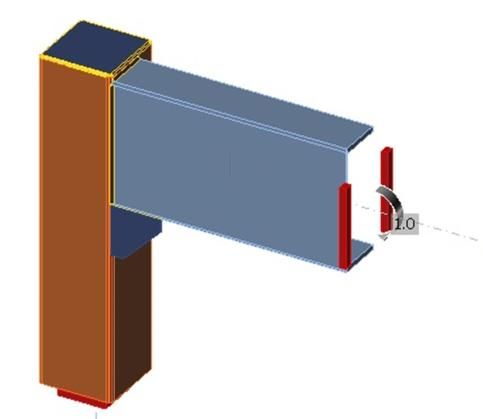
girders from the channels to columns made of square or rectangular pipes (Fig. 2.a) [14-18].
Such a node may have an additional stiffening rib (Fig. 2.b). The subject of this research is
the study of the rotational stiffness of the specified nodal connection of a modular building.
Fig. 2. Node scheme: 1 - rack; 2 - crossbar; 3 - rib; 4 – plug fitting
According to Eurocode 3, the nodes are classified into three groups according to their
rotational stiffness Sj,ini: rigid, semi-rigid and hinged (Fig. 3). Rotational stiffness is the
moment that causes a single rotation of the node. To determine the stiffness of the fastening,
it is necessary to establish the relationship between the rotation angle and the moment in the
node. In general case, this dependence is nonlinear, therefore it is necessary to determine
the limiting moment Mj,Rd, which can support the element attached to the node, or directly
the attachment itself. Initial rotational stiffness Sj,ini is the tangent of the relationship
2/3⸱Mj,Rd to the rotation angle of the section at a given value of the moment. The limiting
values of the rotational stiffness for rigid and hinged fastenings are determined depending
on the bending stiffness of the adjoining elements. The conditions for the classification of
fasteners according to Eurocode 3 are as follows for a rigid, semi-rigid and articulated joint,
respectively:
Sj,ini>Sj,R=kb⸱E⸱Ib/Lb (1)
Sj,R>Sj,ini>Sj,P (2)
Sj,iniE3S Web of Conferences 281, 01045 (2021) https://doi.org/10.1051/e3sconf/202128101045
CATPID-2021 Part 1
Fig. 3. Node classification graph according to dependency M-φ
To determine the initial rotational stiffness through a numerical experiment, the finite
element method can be used (FEM) [7, 19-22]. It is possible to calculate the necessary
parameters to determine Sj,ini via FEM. However, the construction of the design scheme in
FEM is a rather laborious process, while for each node variant it is necessary to create a
new model. The specified drawback is not present in the finite element method component
(CFEM), implemented in the software package IDEA StatiCA [23, 24].
IDEA StatiCA implements the following types of calculations: determination of the
stress-strain state (SSS) of the joint, the calculation of the joint components’ stability
according to Eurocode, the calculation of the ultimate moment (formation of a plastic
hinge), the calculation of the ultimate load on the joint and the element attachment stiffness
calculation. In this study, the last calculation mode is of interest. With it, it is possible to
determine the rotational stiffness of the bolt attachment to the rack. The software complex
calculates Sj,ini independently according to the actual deformations and forces determined in
the calculation process and in accordance with Eurocode 3.
Design model of the node for IDEA StatiCA is shown in Figure 4.
a. b.
Fig. 4. Node model for IDEA StatiCA: a – without a rib; b – with a rib
In the design model, the rack is a supporting element; it has fixings at the bottom in all
six directions. The crossbar is a calculated element, its movements are limited by the
vertical plane. The fastening welds are applied on one side along the outer perimeter of the
channel. A single bending moment is applied to the girder MEd. In this case MEd sets the
4E3S Web of Conferences 281, 01045 (2021) https://doi.org/10.1051/e3sconf/202128101045
CATPID-2021 Part 1
direction of deformation, calculation of the limiting moment Mj,Rd is performed by the
software package in the course of the calculation.
The studies were carried out for the nodal joints obtained by combining a rack from a
square pipe and a girder from a rolled channel. Variants of the connected elements’
combinations are presented in Table 1. The studies were carried out for two cases - a seat
without an edge and a node with an edge. In the studies, the rib is assumed to be 4 mm
thick. The length and width of the rib were taken to be the same (hр ) and varied from 40
mm to 160 mm in 10 mm increments.
3 Results
As a result of the study, the rotational stiffness values of fastening the crossbars to the
columns were obtained. The calculated values Sj,ini are given in Table. 1.
Table 1. Rotational stiffness values Sj,ini, [МN⸱m/rad]
Framework Girder
element [12 [14 [16 [18 [20 [22 [24 [27 [30
80×4 1.6 2.3 3.0 5.5 14.2 – – – –
80×5 2.2 3.2 4.6 8.3 22.9 – – – –
80×6 3.0 4.4 6.5 8.7 46.1 – – – –
90×4 1.5 2.2 2.6 3.9 5.9 11.0 ∞ – –
90×5 2.1 2.9 3.8 5.5 8.4 16.8 ∞ – –
90×6 2.8 3.9 5.1 7.4 11.5 24.2 ∞ – –
Rack
100×4 1.5 2.1 2.4 3.5 4.8 8.6 10.7 71.2 ∞
100×5 2.1 2.9 3.5 4.8 6.5 9.1 16.7 83.1 ∞
100×6 2.8 3.7 4.6 6.3 8.7 11.6 23.6 ∞ ∞
120×4 0.6 2.2 2.4 3.2 4.2 5.1 6.1 9.1 13.6
120×5 1.0 2.9 3.4 4.4 5.6 6.9 8.6 12.9 20.2
120×6 1.4 3.8 4.4 5.7 7.1 8.7 11.3 16.9 28.7
To classify the node type, the rotational stiffnesses values, given in Table. 1, should be
compared with the bending stiffness of the girders, which depends on their span. From
formula (1), the minimum values of the spans at which the nodal connection is considered
rigid, can be derived:
Lb >kb⸱E⸱Ib/ Sj,ini (4)
It was found that the stiffness degree of the assembly strongly depends on the crossbar
span. The larger the span of the girder, the brighter the stiffness of the joint is manifested.
Table 2 shows the calculated values of the girder minimum spans at which the node can be
considered rigid. In table 2, for the elements with a conventionally infinite rotational
stiffness of the fastening, the minimum span is conventionally equal to zero, such a
connection can always be considered rigid. For most of the options considered, a rigid
connection is provided when the girder span is more than 6 m. The exception is the nodal
connections, in which the width of the channel flange is close to the width of the rack
section. In this case, the pipe walls work as stiffeners, this leads to a significant decrease in
the girders rotation angles and an increase in the rotational stiffness Sj,ini. Modular buildings
5E3S Web of Conferences 281, 01045 (2021) https://doi.org/10.1051/e3sconf/202128101045
CATPID-2021 Part 1
are characterized by the spans in the interval 2.4÷6 m, less often up to 9 m, therefore, nodes
with direct abutment of channels to columns made of square pipes should be considered in
the general case "almost rigid". An almost rigid connection is a bond of ultimate stiffness.
The magnitude of this stiffness can be determined numerically, for example, using FEM.
When designing modular buildings, it is recommended to take into account the final
stiffness of the connections in the design models.
Table 2. Minimum girder spans for rigid nodes, [m]
Girder
Element
[12 [14 [16 [18 [20 [22 [24 [27 [30
80×4 10.1 11.3 13.2 10.5 5.7 – – – –
80×5 7.3 8.1 8.6 6.9 3.6 – – – –
80×6 5.4 5.9 6.1 6.6 1.8 – – – –
90×4 10.7 11.8 15.2 14.7 13.7 10.2 0 – –
90×5 7.7 9.0 10.4 10.5 9.6 6.7 0 – –
90×6 5.8 6.7 7.8 7.8 7.0 4.6 0 – –
Rack
100×4 10.7 12.4 16.5 16.4 16.8 13.0 14.3 3.1 0
100×5 7.7 9.0 11.3 12.0 12.4 12.3 9.2 2.7 0
100×6 5.8 7.0 8.6 9.1 9.3 9.6 6.5 0 0
120×4 26.7 11.8 16.5 17.9 19.2 21.9 25.1 24.2 22.6
120×5 16.1 9.0 11.6 13.1 14.4 16.2 17.8 17.1 15.2
120×6 11.5 6.9 9.0 10.1 11.4 12.8 13.6 13.0 10.7
Fig. 5 shows a graph of the limiting rotational stiffness of fastening the girder from the
channel 20 to the columns of various sections. The solid line shows the minimum rotational
stiffness Sj,R, at which the node can be considered rigid. The horizontal lines show the
rotational stiffnesses calculated in IDEA StatiCA. According to the condition (1), a node is
rigid if the horizontal line lies above the curve Sj,R. It can be seen from the graph that only
the connections of the girder with the uprights made of pipes 80×6, 80×5 and 80×4 can be
considered rigid with a span of less than 6 m. With an increase in the dimensions of the
rack, the rotational stiffness is greatly reduced. The ratio of rotational stiffness shown in the
graph is typical for all the considered connection options.
Fig. 5. Boundary rotational stiffness for channel girder 20
6E3S Web of Conferences 281, 01045 (2021) https://doi.org/10.1051/e3sconf/202128101045
CATPID-2021 Part 1
The following is a study of the rib sizes’ effect on the joint rotational stiffness value. It is
known that the minimum joint stiffness decreases following a decrease in the wall thickness
of the strut. Therefore, further research was carried out only for the nodes with a strut
thickness of 4 mm. Fig. 6 shows the results of a rotational stiffness study of fastening
channel 16 with ribs of different sizes.
Fig. 6. Rotational stiffness of fastening channel 16 with an edge to racks of various cross-sections
Fig. 6 shows the rotational stiffness dependence graphs on the rib dimensions. The
horizontal lines show the minimum values Sj,ini for various spans of the girder, in which the
knot is considered rigid. It can be seen in Fig. 6 that the change in the rotational stiffness of
the attachment depending on the size of the rib has a non-linear character. When the rib size
is close to the size of the rack section, there is a sharp increase in Sj,ini. A similar nature of
the change is observed for all the considered variants of cross-sections of girders. The only
exceptions are the channel 20 joints with a rack 80 × 4 and the channel 22 with 90 × 4, for
which, even with a minimum rib size of 40 mm, values of rotational stiffness are achieved
above the minimum corresponding to rigid nodes.
The stiffeners size to ensure a rigid abutment of the channel to the square pipe depends
both on the cross-section of the rack and on the cross-section of the girder. At the same
time, it is difficult to establish a direct relationship between these parameters. Therefore, a
nomogram has been drawn up with the minimum dimensions of the ribs for the considered
cross-sections of the girders, depending on the cross-sections of the racks to which they are
attached (Fig. 7). At the ribs sizes the node shown in Fig. 7 can be considered rigid.
7E3S Web of Conferences 281, 01045 (2021) https://doi.org/10.1051/e3sconf/202128101045
CATPID-2021 Part 1
Fig. 7. Rib sizes for rigid nodes
4 Conclusion
According to the study, the following conclusions can be formulated.
1. Welded UPN channel joints with pipe studs without stiffeners are semi-rigid with
spans typical of modular buildings. The exception is the joints in which the width of the
cross-section is close to the width of the girder cross-section, in which case the column
walls are included in the work as stiffeners, which leads to a significant decrease in the
cross-section rotation angle of the girder cross-section. In the considered variants of the
nodes, this is observed in the joints of channels 24 with uprights from the pipes 90 × 4, 90 ×
5, 90 × 6, channels 27 with a pipe 120 × 6, as well as 30 with the pipes 100 × 4, 100 × 5,
100 × 6. These connections can be considered absolutely rigid.
2. It is recommended to arrange stiffening ribs to ensure a rigid junction of the
channel girder to the square pipe rack. The minimum dimensions of the stiffeners should be
taken according to Fig. 7.
Within the framework of this study, the parameters of the modular buildings’ nodal
connections, in which the nodes behave as rigid, have been determined.
References
1. A. Dorrhofer, М. Rsenthal, G. Staib, Components and Systems: Modular
Constructions. Design, Structure, new Technologies, Basel-Boston-Berlin: Institut fϋr
internationale Architektur-Documentacion Gmbh & Co. KG, 2008.
2. G.M. Badyin, S.A. Sychev, Modern problems of science and education 2-1 (2015).
3. O.N. Beskorovainaya, D.S. Bychkov, Z.A. Gaevskaya, Construction of unique
buildings and structures 1(16), 61-71 (2014).
4. A.N. Mushinsky, S.S. Zimin, Construction of unique buildings and structures, 4(31)
182-193 (2015).
8E3S Web of Conferences 281, 01045 (2021) https://doi.org/10.1051/e3sconf/202128101045
CATPID-2021 Part 1
5. V.S. Shirokov, A.V. Soloviev, Urban planning and architecture 8 (1), 24-27 (2018).
6. V.M. Tusnina, V.D. Platonova, Industrial and civil engineering 9, 28-33 (2020).
7. V.Yu. Alpatov, A.O. Lukin, A.A. Sakharov, Industrial and civil engineering 9, 9-14
(2015).
8. V.S. Shirokov, V.Yu. Alpatov, E.A. Gordeev, Vestnik MGSU 16 (1), 20-29 (2021).
9. I.I. Vedyakov, O.V. Korzhov, B.S. Tsetlin, O. G. Prilutsky, Industrial and Civil
Engineering 6, 20-23 (2009).
10. I.S. Kholopov, V.S. Shirokov, A.V. Soloviev, Bulletin of the Lipetsk State Technical
University 4, 56-62 (2015).
11. Bong-Ho Cho, Jae-Sub Lee, Hongjin Kim, Dae-Jin Kim, Applied Sciences 9, 1929
(2019).
12. Andrew William Lacey, Wensu Chen, Hong Hao, Kaiming Bi, Engineering Structures.
198, 109465 (2019).
13. Andrew William Lacey, Wensu Chen, Hong Hao, Kaiming Bi, Engineering Structures.
227, 111409 (2020).
14. J.Y.R. Liew, Z. Dai, Y.S. Chua, Steel concrete composite systems for modular
constructions of high-rise buildings, 12th International Conference on Advances in
Steel-Concrete Composite Structures (ASCCS 2018), Universitat Politècnica de
València, València, Spain, 2018.
15. Sze Dai PANG, J Y Richard Liew, Ziquan Dai, Yanbo Wang, Prefabricated prefinished
volumetric construction joining techniques review, 2016 Modular and Offsite
Construction (MOC) Summit.: Edmonton, Alberta, Canada, 2016.
16. En-Feng Deng, Liang Zong, Yang Ding, Zhe Zhang, Jun-Feng Zhang, Feng-Wei Shi,
Li-Ming Cai, Shu-Cai Gao, Thin-Walled Structures 155, 106924 (2020).
17. Andrew William Lacey, Wensu Chen, Hong Hao, Kaiming Bi, Engineering Structures
213, 110628 (2020).
18. Andrew William Lacey, Wensu Chen, Hong Hao, Kaiming Bi, Journal of Building
Engineering 16 45-56 (2018).
19. V.V. Nadolskiy, Bulletin of Polotsk State University. Series F. Construction. Applied
Science 8, 121-130 (2018).
20. V.V. Ryumin, Modern building structures made of metal and wood 16, 216-223
(2012).
21. I.S. Kholopov, V.Yu. Alpatov, A.V. Atamanchuk, Building materials, equipment,
technologies of the XXI century 1, 66-68 (2008).
22. S.A. Sokolov, A.N. Kachaun, P.O. Skudalov, S.V. Cheremnykh, Bulletin of the Tver
State Technical University. Series: Construction. Electrical and chemical engineering 2
(2), 36-42 (2019).
23. L. Sabatka, F. Wald, J. Kabelac, D. Kolaja, M. Pospisil, J. of Civil Engineering and
Architecture 9, 895-901 (2015).
24. R.V. Baroev Analysis of steel structures joints by the component finite element method,
Information on http://isicad.ru/ru/articles.php?article_num=20749.
9You can also read