J-Flash User guide of the stand-alone flash programming software - Document: UM08003 Software Version: 7.62
←
→
Page content transcription
If your browser does not render page correctly, please read the page content below
J-Flash

User guide of the stand-alone
 flash programming software

        Document: UM08003
       Software Version: 7.62
            Date: February 16, 2022

   A product of SEGGER Microcontroller GmbH

            www.segger.com
2
Disclaimer
The information written in this document is assumed to be accurate without guarantee. The
information in this manual is subject to change for functional or performance improvements
without notice. SEGGER Microcontroller GmbH (SEGGER) assumes no responsibility for any errors
or omissions in this document. SEGGER disclaims any warranties or conditions, express, implied
or statutory for the fitness of the product for a particular purpose. It is your sole responsibility
to evaluate the fitness of the product for any specific use.
Copyright notice
You may not extract portions of this manual or modify the PDF file in any way without the prior
written permission of SEGGER. The software described in this document is furnished under a
license and may only be used or copied in accordance with the terms of such a license.
© 2004-2018 SEGGER Microcontroller GmbH, Monheim am Rhein / Germany
Trademarks
Names mentioned in this manual may be trademarks of their respective companies.
Brand and product names are trademarks or registered trademarks of their respective holders.
Contact address
SEGGER Microcontroller GmbH
Ecolab-Allee 5
D-40789 Monheim am Rhein
Germany
Tel. +49-2173-99312-0
Fax. +49-2173-99312-28
E-mail: support@segger.com
Internet: www.segger.com
J-Flash User Guide (UM08003) © 2004-2018 SEGGER Microcontroller GmbH3
Manual versions
This manual describes the current software version. If you find an error in the manual or a
problem in the software, please report it to us and we will try to assist you as soon as possible.
Contact us for further information on topics or functions that are not yet documented.
Print date: February 16, 2022
Manual
Revision Date By Description
version
All chapters
6.70 0 200416 LG
Updated for new version of J-Flash.
Chapter “Target systems”
6.70 0 200414 LG * Section “Which devices can be programmed by J-Flash?”: Added refer-
ence to SEGGER Wiki article about ’Open Flash Loader’.
All chapters
6.64 0 200324 LG
Updated for recently added cross-platform availability of J-Flash.
Chapter “Settings”
6.55b 0 191114 FF
* Section “Init steps”: Added info about Verify/Write&Verify.
Chapter “Command Line Interface”
6.49 4 190814 LG * Section “Programming multiple targets in parallel”: Updated batch
scripts.
Chapter “Command Line Interface”
6.48b 0 190812 AB * Section “Command line options”: Updated CL option -jlinkdevicesxml-
path.
Chapter “Getting Started”
6.32 4 190418 FF * Section “Menu structure”: added a note in the table “Target menu ele-
ments” for Manual Programming > Program.
Chapter “Settings”
6.32 3 190327 MF * Section “Production setting”: added clarification note for target power
supply.
Chapter “Command Line Interface”
6.32 2 180621 LG
* Section “Command line options”: Added new CL option -setcpuidcode.
Chapter “Command Line Interface”
* Section “Command line options”: Added new CL option -saveas.
6.32 1 180427 LG
* Section “Command line options”: Updated CL option -merge.
* Section “Command line options”: Updated CL option -setrxidcode.
Screenshots updated.
Chapter “Command Line Interface”
6.30 2 180417 NV * Section “Command line options”: Added new CL option -hide.
* Section “Command line options”: Updated CL option -jflashlog.
* Section “Command line options”: Updated CL option -jlinklog.
Screenshots updated.
6.30 1 180216 LG Chapter “Settings”
* Added section “Performance settings”
Chapter “Command Line Interface”
* Section “Command line options”
5.02c 0 150914 RH
Added new commands:
-verifycrca, verifycrcs and verifycrcc
Chapter “Command Line Interface”
5.02a 0 150907 EL
* Section “Command line options” updated.
Chapter “Command Line Interface”
5.00c 0 150611 EL
* Section “Programming multiple targets in parallel” updated.
Chapter “Command Line Interface”
4.98 2 150427 EL * Section “Command line options”
Added new command: -ip and -USB.
Chapter “Background information”
4.98 1 150320 AG * Section “CRC of current data file”
Polynomial corrected.
Chapter “Command Line Interface”
4.98 0 150113 NG
Changed “JFlashARM.exe” to “JFlash.exe”.
Chapter “Device specifics”
4.96 0 150109 EL * Section “ST” updated.
* Section “Freescale” updated.
J-Flash User Guide (UM08003) © 2004-2018 SEGGER Microcontroller GmbH4
Manual
Revision Date By Description
version
Chapter “Device specifics”
4.82 0 140307 AG
* Section “ST” updated.
Chapter “Command Line Interface”
4.80 0 131220 AG
* Section “Command line options” updated.
Chapter “Getting Started”
4.73c 0 130703 JL
* Added Section “Start Dialog”
Chapter “Settings”
4.66 1 130320 EL * Section “CPU Settings”
Added description for the core ID “Mask” field
Chapter “Introduction”
4.66 0 130221 JL * Section “What is J-Flash”
Added Linux and Mac OSX
Chapter “Command Line Interface”
4.58 0 121113 JL * Section “Batch processing” updated.
* Section “Command line options” updated.
Chapter “Getting Started”
* Section “Menu structure” updated
Chapter “Settings”
* Section “CPU Settings” updated
4.52 0 120807 EL
Chapter “Command Line Interface”
* Section “Programming multiple targets in parallel” added.
Chapter “Getting Started”
* Section “Sample Projects” updated.
Chapter “Create a new J-Flash project”
4.51i 0 120724 EL
* Section “Configuration for serial number programming” added.
Chapter “Background information”
4.42b 0 120217 AG
* Section “CRC of current data file” added.
4.24 0 110216 AG Chapter “Target systems” updated.
Chapter “Command Line Interface”
4.16 1 100817 AG
* Section “Command line options” corrected.
Chapter “Settings”
4.16 0 100723 KN
* Section “Init sequence” updated.
Chapter “Device specifics”
4.10 4 091204 AG
* Section “Freescale” added.
Chapter “Command Line interface”
4.10 2 090918 AG
* Section “Command line options” updated.
Chapter “Device specifics”
4.10 1 090902 AG
* Section “ST Microelectronics” updated.
Chapter “Device specifics”
4.10 0 090825 AG
* Section “ST Microelectronics” updated.
Chapter “Introduction”
4.04 1 090414 AG
* Section “What is J-Flash?” updated.
Chapter “Command Line Interface”
4.04 0 090204 AG * Section “Overview” updated.
* Section “Command Line Options” updated.
Chapter “Target systems”
* Section “Supported Flash Devices” updated
3.97e 0 081204 KN
Chapter “Settings”
* Section “Init sequence” corrected
Chapter “Working with J-Flash” renamed to
“Create a new J-Flash project.”
Chapter “Create a new J-Flash project”
3.91n 0 080923 AG Chapter “Settings”
* Section “Init sequence” updated.
Chapter “Command Line Interface” updated.
* Section “Create a new J-Flash project” updated.
Chapter “Targets”
3.90 0 080811 AG
* Section “Supported Microcontrollers” updated.
Chapter “Licensing”
3.80 2 080408 AG * Section “Introduction” added.
* Section “License types” added.
J-Flash User Guide (UM08003) © 2004-2018 SEGGER Microcontroller GmbH5
Manual
Revision Date By Description
version
Chapter “Target systems”
* Section “Supported Microcontrollers” updated.
3.80 1 080311 AG
Chapter “Working with J-Flash”
* Section “Create a new J-Flash project” updated.
Chapter “Device specifics” added.
3.80 0 080206 SK Chapter “Target systems”
* Section supported MCUs updated.
Chapter “Installation” updated.
Chapter “Command Line Interface”:
3.68 1 070508 SK
* Section “Batch processing” added.
Various improvements.
Chapter “Target systems” updated.
3.66 1 070322 SK
Chapter “Getting started” updated.
3.46 4 061222 SK Section “About” and company description added.
3.46 3 061124 OO Chapter “Performance” updated.
3.46 2 061121 OO Chapter “Performance” updated.
3.46 1 060929 TQ Update supported target devices.
3.42 1 060912 TQ Update supported target devices.
3.36 1 060801 TQ Update supported target devices.
3.24 1 060530 TQ Update supported target devices.
3.00 2 060116 OO Screenshots updated.
3.00 1 060112 TQ Nothing changed. Just a new software version.
2.14 0 051025 TQ Update supported target devices.
2.10 0 050926 TW Added troubleshooting section.
2.04 0 050819 TQ Nothing changed. Just a new software version.
2.02 0 050808 TW Command line added.
2.00 0 050707 TW Initial Version
J-Flash User Guide (UM08003) © 2004-2018 SEGGER Microcontroller GmbH6 J-Flash User Guide (UM08003) © 2004-2018 SEGGER Microcontroller GmbH
7

    About this document

    Assumptions
    This document assumes that you already have a solid knowledge of the following:
    •   The software tools used for building your application (assembler, linker, C compiler).
    •   The C programming language.
    •   The target processor.
    •   DOS command line.
    If you feel that your knowledge of C is not sufficient, we recommend The C Programming Lan-
    guage by Kernighan and Richie (ISBN 0--13--1103628), which describes the standard in C pro-
    gramming and, in newer editions, also covers the ANSI C standard.

    How to use this manual
    This manual explains all the functions and macros that the product offers. It assumes you have
    a working knowledge of the C language. Knowledge of assembly programming is not required.

    Typographic conventions for syntax
    This manual uses the following typographic conventions:

                Style                                            Used for

    Body                          Body text.
                                  Text that you enter at the command prompt or that appears on
    Keyword
                                  the display (that is system functions, file- or pathnames).
    Parameter                     Parameters in API functions.
    Sample                        Sample code in program examples.
    Sample comment                Comments in program examples.
                                  Reference to chapters, sections, tables and figures or other doc-
    Reference
                                  uments.
    GUIElement                    Buttons, dialog boxes, menu names, menu commands.
    Emphasis                      Very important sections.

J-Flash User Guide (UM08003)                                  © 2004-2018 SEGGER Microcontroller GmbH
8 J-Flash User Guide (UM08003) © 2004-2018 SEGGER Microcontroller GmbH
9

    Table of contents

    1   Introduction ..................................................................................................................11
        1.1     What is J-Flash? .......................................................................................... 12
                1.1.1 Supported Operating Systems .............................................................12
                1.1.2 Features ...........................................................................................12
        1.2     Assumptions ................................................................................................ 13
        1.3     Requirements .............................................................................................. 14

    2   Licensing ..................................................................................................................... 15

    3   Getting Started ............................................................................................................16
        3.1     Setup ......................................................................................................... 17
                3.1.1 What is included? ..............................................................................17
        3.2     Using J-Flash for the first time ...................................................................... 18
                3.2.1 Welcome dialog .................................................................................18
                3.2.2 Sample Projects ................................................................................ 18
                3.2.3 Creating a new J-Flash project ............................................................18
                3.2.4 Creating a new init sequence ............................................................. 19
                3.2.5 Serial number programming ............................................................... 21
        3.3     Menu structure ............................................................................................ 25

    4   Settings ....................................................................................................................... 28
        4.1     Project Settings ........................................................................................... 29
                4.1.1 General Settings ............................................................................... 29
                4.1.2 Target Interface Settings ....................................................................30
                4.1.3 MCU Settings ....................................................................................32
                4.1.4 Flash Settings ...................................................................................36
                4.1.5 Production settings ............................................................................39
                4.1.6 Performance settings ......................................................................... 41
        4.2     Global Settings ............................................................................................ 42

    5   Command Line Interface ............................................................................................ 43
        5.1     Overview .....................................................................................................44
        5.2     Command line options .................................................................................. 45
        5.3     Batch processing ..........................................................................................47
        5.4     Programming multiple targets in parallel ......................................................... 48

J-Flash User Guide (UM08003)                                                      © 2004-2018 SEGGER Microcontroller GmbH
10
6 Device specifics .......................................................................................................... 50
7 Target systems ........................................................................................................... 51
7.1 Which devices can be programmed by J-Flash? ................................................52
7.2 Supported microcontrollers ............................................................................53
7.2.1 Supported Flash Devices .................................................................... 53
8 Performance ................................................................................................................54
9 Background information .............................................................................................. 55
9.1 CRC of current data file ................................................................................ 56
10 Support ......................................................................................................................57
10.1 Troubleshooting .......................................................................................... 58
10.1.1 General procedure ........................................................................... 58
10.1.2 Typical problems ............................................................................. 58
10.2 Contacting support ..................................................................................... 60
J-Flash User Guide (UM08003) © 2004-2018 SEGGER Microcontroller GmbHChapter 1
Introduction
The following chapter introduces J-Flash, highlights some of its features, and lists its re-
quirements on host and target systems.
J-Flash main window
J-Flash User Guide (UM08003) © 2004-2018 SEGGER Microcontroller GmbH12 CHAPTER 1 What is J-Flash?
1.1 What is J-Flash?
J-Flash is a stand-alone flash programming software for PCs running Windows, Linux or
macOS.
J-Flash has an intuitive user interface and makes programming flash devices convenient. J-
Flash requires a J-Link / Flasher, to interface to the hardware. It is able to program internal
and external flash at very high speeds, upwards of 550 KBytes/s depending on the chip.
Another notable feature is smart read back, which only transfers non-blank portions of
the flash, increasing the speed of read back greatly. These features along with its ability
to work with any ARM7/ARM9/ARM11, Cortex-M0/M1/M3/M4/M7, Cortex-A5/A8/A9/R4/R5
and Renesas RX600 chip makes it a great solution for most projects.
1.1.1 Supported Operating Systems
The following operating systems are supported:
• Microsoft Windows 2000
• Microsoft Windows XP
• Microsoft Windows XP x64
• Microsoft Windows 2003
• Microsoft Windows 2003 x64
• Microsoft Windows Vista
• Microsoft Windows Vista x64
• Microsoft Windows 7
• Microsoft Windows 7 x64
• Microsoft Windows 8
• Microsoft Windows 8 x64
• Microsoft Windows 10
• Microsoft Windows 10 x64
• Linux
• macOS 10.5 and higher
1.1.2 Features
• Any ARM7/ARM9/ARM11, Cortex-M0/M1/M3/M4/M7, Cortex-A5/A8/A9/R4/R5 and
Renesas RX600 core supported
• Microcontroller (internal flash) support.
• Support for most external flash chips (For more information please refer to Target
systems on page 51).
• High speed programming: up to 550 KBytes/s* (depending on flash device).
• Smart read back: only non-blank portions of flash are transferred and saved.
• Free evaluation licenses available.
• Verbose logging of all communication.
• .hex, .mot, .srec, .bin and .elf support.
• Intuitive user interface.
* = Measured with J-Link V10
J-Flash User Guide (UM08003) © 2004-2018 SEGGER Microcontroller GmbH13 CHAPTER 1 Assumptions
1.2 Assumptions
This user manual assumes that you already possess working knowledge of the J-Link device.
If you feel that your knowledge of J-Link is not sufficient, we recommend the J-Link Manual
(UM08001), which describes the device and its use in detail.
J-Flash User Guide (UM08003) © 2004-2018 SEGGER Microcontroller GmbH14 CHAPTER 1 Requirements
1.3 Requirements
• J-Link / Flasher
• Supported operating system (see Supported Operating Systems on page 12)
• Interface from Host to probe (USB, Ethernet, WiFi, …)
• Supported device/core (see Supported microcontrollers on page 53)
J-Flash User Guide (UM08003) © 2004-2018 SEGGER Microcontroller GmbHChapter 2
Licensing
J-Flash may be installed on as many host machines as you want. Without a license key
J-Flash can still be used to open project files, read from connected devices, blank check
target memory, verify data files and so on. However to actually program devices via J-Flash
and J-Link, a valid license is required. For an overview which SEGGER products come with
a built-in license for J-Flash, please refer to the J-Link Model overview . All Flasher models
come with a built-in license for J-Flash.
J-Flash User Guide (UM08003) © 2004-2018 SEGGER Microcontroller GmbHChapter 3
Getting Started
This chapter presents an introduction to J-Flash. It provides an overview of the included
sample projects and describes J-Flash’s menu structure in detail.
J-Flash User Guide (UM08003) © 2004-2018 SEGGER Microcontroller GmbH17 CHAPTER 3 Setup
3.1 Setup
The J-Link setup procedure required in order to work with J-Flash is described in chapter 2
of the J-Link / J-Trace User Guide (UM08001). The J-Link / J-Trace User Guide (UM08001) is
part of the J-Link Software and Documentation Pack which is available for download under
segger.com/jlink-software.html .
3.1.1 What is included?
The following table shows the contents of all subdirectories of the J-Link Software and
Documentation Pack with regard to J-Flash:
Directory Contents
The J-Flash application. Please refer to the J-Link Manual (UM08001)
.
for more information about the other J-Link related tools.
Contains the J-Flash documentation and the other J-Link related man-
.\Doc
uals.
Two *.csv files for the J-Flash internal management of supported
.\ETC\JFlash
MCU’s und flash chips.
.\Sam-
Contains sample projects with good default settings (see section
ples\JFlash
Sample Projects on page 18 for further details).
\ProjectFiles
J-Flash User Guide (UM08003) © 2004-2018 SEGGER Microcontroller GmbH18 CHAPTER 3 Using J-Flash for the first time
3.2 Using J-Flash for the first time
3.2.1 Welcome dialog
When starting J-Flash, by default a startup dialog pops up which gives the user two options
how to proceed.
Welcome Dialog
The startup dialog provides the following options:
• Open existing project: Select a project from the list of recent projects or press
Other… to open another existing project.
• Create new project: Opens another dialog to create a new J-Flash project
If “Do not show this message again.” is checked, J-Flash will execute the option currently
selected automatically on future starts without showing the welcome dialog again.
3.2.2 Sample Projects
For some setups, special settings / configurations needs to be done in the J-Flash project
(e.g. PLL initialization, external bus interface initialization, script files, etc…). Therefore,
the J-Link Software and Documentation Pack already includes some example projects for
various special setups which can be used as reference for custom setups.
Those project files can be found in the \Samples\JFlash\ProjectFiles subdirectory of the J-
Link Software and Documentation Pack installation directory.
3.2.3 Creating a new J-Flash project
The recommend way of getting started with J-Flash is to use the Create New Project
wizard.
• Start by selecting the Create new project option inside the Welcome dialog or by
selecting File -> New project
• The new project wizard will launch, which looks like as follows:
New project wizard
• Select the target device, the target interface and interface speed according to the setup.
If only a core is selected, the target endianness must be specified as well.
• Click OK
The created Project file is now ready for use. More sophisticated settings can be configured
in the Project settings. Please refer to Project Settings on page 29.
J-Flash User Guide (UM08003) © 2004-2018 SEGGER Microcontroller GmbH19 CHAPTER 3 Using J-Flash for the first time
3.2.4 Creating a new init sequence
Many microcontrollers require a custom init sequence to initialize the target hardware, for
example to initialize the PLL, disable the watchdog or define the wait states of the flash.
This means that an compatible init sequence for the microcontroller must be built, if a new
project is created or an existing project is modified.
A custom init sequence can be created or updated in the Init. steps tab of the Project
settings menu. Click the + button to open the Add custom CPU step dialog.
Init Steps: Add action dialog
In the Action Type dropdown menu all available actions are listed. Depending on the type
of action, there are either one or two textboxes next to the dropdown menu, which can be
used to enter the required parameter. The Comment text box should be used to enter a
short description of the action. For a list of all valid actions which can be used in an init
sequence, please refer to Init steps on page 33.
J-Flash User Guide (UM08003) © 2004-2018 SEGGER Microcontroller GmbH20 CHAPTER 3 Using J-Flash for the first time
3.2.4.1 Example init sequence
A good example of a typical init sequence is the init sequence of an AT91SAM7 CPU. The
following example is excerpted from the J-Flash project for the AT91SAM7S256.
The example init sequence step by step
0. Reset the target with J-Link reset strategy 8 and 0 delay.
1. Disable the watchdog by writing to the Watchdog Timer Mode Register.
2. Set flash wait states by writing to the MC Flash Mode Register.
3. Set the PLL by writing to power management controller.
4. Set a delay of 200ms.
5. Set the PLL and the divider by writing to PLL Register of the power management
controller.
6. Set a delay of 200ms.
7. Set the master and processor clock by writing to the Master Clock Register of the power
management controller.
The steps implemented in J-Flash:
MCU settings: Init Steps: Example
J-Flash User Guide (UM08003) © 2004-2018 SEGGER Microcontroller GmbH21 CHAPTER 3 Using J-Flash for the first time
3.2.5 Serial number programming
J-Flash supports programming of serial numbers. In order to use the serial number pro-
gramming feature, the J-Flash project to be used as well as some files in the working folder
(depending on the configuration) need to be configured first.
In general, J-Flash supports two ways of programming a serial number into the target:
1. Programming continuous serial numbers.
Serial number is 1-4 bytes in size. Start serial number, increment, serial number size
and address have to be configured in the J-Flash project production settings.
2. Programming custom serial numbers from a serial number list file.
Start line into serial number list file to get next serial number bytes, line increment,
serial number size and address is configured in J-Flash production project settings.
Serial number list file needs to be specified and created by user.
In the following, some generic information how to setup a serial number programming
configuration are given.
3.2.5.1 Serial number settings
In order to use the serial number feature, the J-Flash project has to be configured to enable
programming a serial number at a specific address. This is done by enabling the Program
serial number option as shown in the screenshot and table below:
Program serial number option
J-Flash User Guide (UM08003) © 2004-2018 SEGGER Microcontroller GmbH22 CHAPTER 3 Using J-Flash for the first time
Setting Meaning
Address The address the serial number should be programmed at.
The length of the serial number (in bytes) which should be programmed.
• If no serial number list file is given, J-Flash allows to use a 1-4 byte
serial number. If 8 is selected as length, the serial number and its com-
plementary is programmed at the given address.
Len
• In case a serial number list file is given, J-Flash will take the serial num-
ber bytes from the list file. If a serial number in the list file does not
define all bytes of Len, the remaining bytes are filled with 0s. No com-
plements etc. are added to the serial number.
• In case no serial number list file is given, Next SN is the next serial num-
ber which should be programmed. The serial number is always stored in
little endian format in the flash memory.
• In case a serial number list file is given, Next SN describes the line of the
Next SN
serial number list file where to read the next serial number bytes from.
J-Flash starts counting with line 0, so in order to start serial number
programming with the first line of the SNList.txt, Next SN needs to be
set to 0.
Increment Specifies how much Next SN is incremented.
3.2.5.2 Serial number file
When starting the program process Target -> Production Programming, J-Flash will
create a serial number file named as _Serial.txt. The file is gen-
erated based on the serial number settings in the J-Flash project and will contain the value
defined by the Next SN option. The serial number file can also be manually edited by the
user, since the serial number is written ASCII.
3.2.5.3 Serial number list file
In order to program custom serial numbers which can not be covered by the standard
serial number scheme provided by J-Flash (e.g. when programming non-continuous serial
numbers or having gaps between the serial numbers), a so called serial number list file
needs to be created by the user.
When selecting Target -> Production Programming, J-Flash will check for a serial num-
ber list file named as _SNList.txt in the directory where the J-Flash
project is located. The serial number list file needs to be created manually by the user and
has the following syntax:
• One serial number per line
• Each byte of the serial number is described by two hexadecimal digits.
Example
An 8-byte serial number should be programmed at address 0x08000000. It should be pro-
grammed as follows in the memory:
0x08000000: 0x01 0x02 0x03 0x04 0x55 0x66 0x77 0x88
The serial number list file should look as follows:
0102030455667788
J-Flash User Guide (UM08003) © 2004-2018 SEGGER Microcontroller GmbH23 CHAPTER 3 Using J-Flash for the first time
SN list example
The number of bytes to read per line is configured via the Len option in J-Flash. For more
information, please refer to Serial number settings on page 21.
Which line J-Flash will read at the next programming cycle is configured via the Next SN
option. For more information, please refer to Serial number settings on page 21. In this
case Next SN needs to be set to 0, since programming should be started with the serial
number bytes defined in the first line of the file.
Note
If the number of bytes specified in a line of the serial number list file is less than the
serial number length defined in the project, the remaining bytes are filled with 0s by
Flasher ARM.
Note
If the number of bytes specified in a line of the serial number list file is greater than
the serial number length defined in the J-Flash project, the remaining bytes will be
ignored by J-Flash
Note
When using Windows 7, please make sure that the used project file is located at a
folder with write permission.
3.2.5.4 Programming process
J-Flash will increment the serial number in _Serial.txt by the value
defined in Increment, after each successful programming cycle.
3.2.5.5 Sample setup
In the following a small sample is given how to setup J-Flash for serial number program-
ming. In the following sample, 4-byte serial numbers starting at 1234567 (0x12D687) shall
be programmed at address 0x08001000.
Defining serial number address, length, start value and increment
In the J-Flash project the following needs to be defined:
• Address is 0x08001000
• Len is 4 (bytes)
• Next SN is 1234567
J-Flash User Guide (UM08003) © 2004-2018 SEGGER Microcontroller GmbH24 CHAPTER 3 Using J-Flash for the first time
• Increment is 1
Program serial number option
Now J-Flash is prepared to program the 8-byte serial number. After programming the serial
number, J-Flash creates the _Serial.txt.
Serial number file
J-Flash User Guide (UM08003) © 2004-2018 SEGGER Microcontroller GmbH25 CHAPTER 3 Menu structure
3.3 Menu structure
The main window of J-Flash contains seven dropdown menus (File, Edit, Target, Options,
View, Help).
File menu elements
Command Description
Opens a data file that may be used to flash the target device.
Open data file… The data file must be one of the following: Intel HEX file, Motoro-
la S file, Binary file or ELF file (.hex, .mot, .srec, .bin or .elf).
Merges two data files (.hex, .mot, .srec, .bin or .elf).
All gaps will be filled with FF. Find below a short example of
merging two data files named, File0.bin and File1.bin into
File3.bin.
File0.bin --> Addr 0x0200 - 0x02FF
File1.bin --> Addr 0x1000 - 0x13FF
Merge data file…
Merge File0.bin & File1.bin
0x0200 - 0x02FF Data of File0.bin
0x0300 - 0x0FFF gap (will be filled with 0xFF if image is saved as
*.bin file)
0x1000 - 0x13FF Data of File1.bin
Can be saved in new data file (File3.bin).
Save data file Saves the data file that currently has focus.
Saves the data file that currently has focus using the name and
Save data file as…
location given.
New project Creates a new project (See Creating a new J-Flash project)
Opens a J-Flash project file. Please note that only one project file
Open project may be open at a time. Opening a project will close any other
project currently open.
Save project Saves a J-Flash project file.
Save project as… Saves a J-Flash project file using the name and location given.
Close project Closes a J-Flash project file.
Saves a .CFG file for stand-alone mode using the name and loca-
Save Flasher config
tion given. Please refer to the Flasher documentation (UM08022)
file…
for more information regarding stand-alone mode.
Saves a .DAT file for stand-alone mode using the name and loca-
Save Flasher data
tion given. Please refer to the Flasher documentation (UM08022)
file…
for more information regarding stand-alone mode.
Prepares a connected Flasher for stand-alone mode using the
Download config & current project and the data file which had focus most recently.
data file to Flasher Please refer to the Flasher documentation (UM08022) for more
information regarding stand-alone mode.
Download serial Downloads a serial number file to a connected Flasher. Please re-
number file to Flash- fer to the Flasher documentation (UM08022) for more informa-
er tion regarding stand-alone mode.
Recent Files Contains a list of the most recently open data files.
Recent Projects Contains a list of the most recently open project files.
Exit Exits the J-Flash application.
J-Flash User Guide (UM08003) © 2004-2018 SEGGER Microcontroller GmbH26 CHAPTER 3 Menu structure
Edit menu elements
Command… Description
Relocates the start of the data file to the supplied hex offset from
Relocate…
the current start location.
Deletes a range of values from the data file, starting and ending
Delete range… at given addresses. The End address must be greater than the
Start address otherwise nothing will be done.
Eliminate blank ar-
Eliminates blank regions within the data file.
eas…
Target menu elements
Command Description
Creates a connection through the Flasher using the configura-
Connect tion options set in the Project settings… of the Options dropdown
menu.
Disconnects a current connection that has been made through
Disconnect
the Flasher.
Generates data which can be used to test if the flash can be pro-
Test > Generate test
grammed correctly. The size of the generated data file can be de-
data
fined.
Writes data of an specified size to an defined address, reads the
Test > Test speed
written data back and measures the up- and download speed.
Test > Show CFI in-
Reads the CFI query information of a CFI compliant flash device.
fo
Test > Hardware > Sets the RS232 Busy signal of a connected Flasher. Can be used
Activate BUSY to test the RS232 setup.
Test > Hardware > Resets the RS232 Busy signal of a connected Flasher. Can be
Deactivate BUSY used to test the RS232 setup.
Test > Hardware > Sets the RS232 OK signal of a connected Flasher. Can be used to
Activate OK test the RS232 setup.
Test > Hardware > Resets the RS232 OK signal of a connected Flasher. Can be used
Deactivate OK to test the RS232 setup.
Performs a sequence of steps, which can be configured in the
Production tab of the Project settings. Additionally, the first step
Production Program-
executed are the init steps and the last step executed are the
ming
exit steps, which both can be configured in the MCU tab of the
project settings.
Manual Program-
Secures the MCU.
ming > Secure Chip
Manual Program-
ming > Unsecure Unsecures the MCU.
Chip
Manual Program-
Checks flash to see if it is empty.
ming > Check Blank
Manual Program-
ming > Erase Sec- Erases all selected flash sectors.
tors
Manual Program-
Erases the entire chip.
ming > Erase Chip
J-Flash User Guide (UM08003) © 2004-2018 SEGGER Microcontroller GmbH27 CHAPTER 3 Menu structure
Command Description
Programs the chip using the currently active data file. Please
Manual Program-
note that no erase / blank check is performed prior programming
ming > Program
so the flash is assumed to be in an erased state.
Manual Program-
Programs the chip using the currently active data file and then
ming > Program &
verifies that it was written successfully.
Verify
Manual Program-
Verifies the data found on the chip with the data file.
ming > Verify
Manual Program-
Reads back the data found in the selected sectors and creates a
ming > Read back >
new data file to store this information.
Selected Sectors
Manual Program-
Reads back the data found on the chip and creates a new data
ming > Read back >
file to store this information.
Entire chip
Manual Program-
Reads back the data found in a range specified by the user and
ming > Read back >
creates a new data file to store this information.
Range
Manual Program-
ming > Start Appli- Starts the application.
cation
Options menu elements
Command Description
Project settings… Opens the project settings dialog.
Global settings… Opens the global settings dialog.
View menu elements
Command Description
Show project infor-
Opens and/or sets the focus to the project window.
mation
Show log Opens and/or sets the focus to the log window.
Help menu elements
Command Description
Opens this document in the default .PDF application of the sys-
J-Flash User Guide
tem.
Opens the J-Link Manual (UM08001) in the default .PDF applica-
J-Link User Guide
tion of the system.
Shows a dialog with licensing information. The serial number of a
Licenses…
connected J-Link may be read and licenses added or removed.
About… J-Flash and company information.
J-Flash User Guide (UM08003) © 2004-2018 SEGGER Microcontroller GmbHChapter 4
Settings
The following chapter provides an overview of the program settings. Both general and per
project settings are considered.
J-Flash User Guide (UM08003) © 2004-2018 SEGGER Microcontroller GmbH29 CHAPTER 4 Project Settings
4.1 Project Settings
Project settings are available from the Options menu in the main window or by using the
ALT + F7 keyboard shortcut.
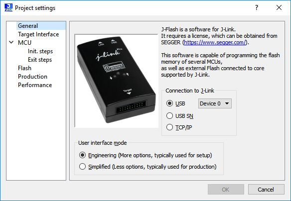
4.1.1 General Settings
This dialog is used to configure the connection to the J-Link / Flasher.
The J-Link / Flasher can either be connected to the host system of J-Flash directly via USB,
Ethernet or WiFi, or it can be connected through the J-Link Remote Server running on a
remote system.
For more information on the operation of J-Link / Flasher, please refer to the J-Link Manual
(UM08001) . For more information on the J-Link Remote Server, please refer to: ( J-Link
Remote Server overview ) .
General Settings
USB
If this option is checked, J-Flash will connect to J-Link / Flasher over the USB port. The de-
fault device number is 0. For more information about how to use multiple J-Link / Flasher on
one PC, please see also the chapter “Working with J-Link” of the J-Link Manual (UM08001).
USB S/N
If this option is checked, J-Flash will connect to J-Link / Flasher over the USB port. J-Flash
will only use the J-Link / Flasher with the specified S/N and any operation will fail if the J-
Link / Flasher with specified S/N is not connected or cannot be used for any reason.
TCP/IP
If this option is checked, J-Flash will connect to J-Link / Flasher via TCP/IP. This should
be configured for SEGGER probes connected via Ethernet directly (e.g. J-Link PRO, Flasher
PRO, …) or using the J-Link Remote Server. The hostname (or IP address) of the system
to connect to be may be entered in the textbox for TCP/IP. For connections via the J-Link
Remote Server the according connection string may be entered.
User interface mode
Select the Engineering radio button when setting up a project or
select the Simplified radio button when using J-Flash in production environments.
J-Flash User Guide (UM08003) © 2004-2018 SEGGER Microcontroller GmbH30 CHAPTER 4 Project Settings
In the simplified user interface some options are disabled to reduce possible error sources
in the production phase.
4.1.2 Target Interface Settings
This dialog is used to configure the interface connection to the target.
Target Interface Settings
4.1.2.1 Interface Speed
The interface speed used before and after initialization can be configured. The interface
speed before init is used to communicate with the target before and during execution of
the custom initialization sequence (described in the section Init steps on page 33). The
interface speed after init is used to communicate after executing the custom initialization
sequence. This is useful if a target running at slow speed and the users wants to set up
a PLL in the initialization sequence.
For more information about the different types of interface speed please see the chapter
“Setup” of the J-Link Manual (UM08001).
4.1.2.2 JTAG scan chain
The “JTAG scan chain information” box allows to configure a JTAG scan chain with multiple
devices on it.
J-Flash User Guide (UM08003) © 2004-2018 SEGGER Microcontroller GmbH31 CHAPTER 4 Project Settings
A “simple” JTAG scan chain configuration
A “detailed” JTAG scan chain configuration
In a scan chain configuration with multiple devices, the TCK and TMS lines of all JTAG
devices are connected, while the TDI and TDO lines form a ring.
J-Flash User Guide (UM08003) © 2004-2018 SEGGER Microcontroller GmbH32 CHAPTER 4 Project Settings
JTAG-chain
The position of the device to connect with J-Flash is selected from the Position dropdown
menu. The Instruction Register length (IRLen) of a device is defined by its manufacturer.
For ARM cores, the IRLen is always four, which is why the value of IRLen is by default set to
four times the position indicated. This works fine for ARM only scan chains. However, if any
non-ARM devices are introduced to the scan chain the IRLen must be modified accordingly.
4.1.3 MCU Settings
This dialog allows the selection of microcontroller dependent settings.
MCU Settings
J-Flash User Guide (UM08003) © 2004-2018 SEGGER Microcontroller GmbH33 CHAPTER 4 Project Settings
J-Flash can be used to program both external or internal flash memory. In order to use J-
Flash with an external flash device, the proper Core must be selected.
To program internal flash devices, the respective microcontroller must be selected in the
Device list by clicking the … button. If a microcontroller is not found on this list, contact
SEGGER, as new microcontrollers are continuously being added.
Device
Select the respective microcontroller from the list to program internal flash devices. In
order to program external flash, select the device or core from the list.
Clock speed
For some devices, the actual CPU clock frequency in Hz of the MCU is required to guarantee
accurate operation of J-Flash. By default, J-Flash uses the “Auto” CPU speed detection
feature.
Endianness
The compatible endianness of the selected device is set automatically if possible. Otherwise,
select little endian or big endian from the dropdown menu accordant to the device.
4.1.3.1 Check core ID
If the core ID is known for the device to be programmed, it can be used to verify that the
device in communication with the J-Link / Flasher is the intended device. The core ID for all
listed devices is known, therefore this value is filled in automatically if a device is selected
and can not be modified. If only a core family is selected, the core ID field can be modified.
Mask
This option allows the user to mask out specified bits of the core ID. All bits set to 0 in
“Mask” are not taken into account when comparing the Code ID found by the J-Link / Flasher
with the Core ID entered in J-Flash.
Example:
Values Check result
Core ID entered: 0x3BA00477
Core ID found: 0x4BA00477 Failed
Mask: 0xFFFFFFFF
Core ID entered: 0x3BA00477
Core ID found: 0x4BA00477 Passed
Mask: 0x0FFFFFFF
The code ID check works as follows:
CoreIDFound &= Mask;
CoreIDEntered &= Mask;
if (CoreIDFound != CoreIDEntered) {
return Error; // Core ID check failed.
}
4.1.3.2 Target RAM settings
The target RAM is used during flash programming to store the RAMCode. This RAM is called
work RAM. The “Target RAM settings” define the start address and the size size of the
work RAM.
4.1.3.3 Init steps
Many microcontrollers require an initialization sequence for different reasons: When pow-
ered on, the PLL may not be initialized, which means the chip is very slow, or a watchdog
J-Flash User Guide (UM08003) © 2004-2018 SEGGER Microcontroller GmbH34 CHAPTER 4 Project Settings
must be disabled manually. To use these chips the user must first perform the required
initialization.
This dialog allows the user to enter a custom initialization sequence using a predefined list
of operations. After choosing an operation and corresponding values to be associated with
the operation, a comment may be added to make it easier for others to determine its effect.
The following list shows all valid commands which can be used in an init sequence:
Command Value0 Value1 Description
Length of
Delay -- Sets a delay.
the delay
DisableMMU -- -- Disables the MMU.
Disables JTAG checks. Some CPUs
(e.g. TMS470R1B1M) report JTAG
communication errors while initial-
Disable Checks -- --
izing, so that they can not be pro-
grammed if the JTAG communica-
tion checks are enabled.
Enables JTAG checks. This option
Enable Checks -- --
is activated by default.
Go -- -- Starts the CPU
Halt -- -- Halts the CPU
Resets the CPU. Refer to the J-Link
J-Link reset Length of Manual (UM08001) for an detailed
Reset
type the delay explanation of the different reset
types.
Reads 8bit from a given address
Read 8bit Address (Hex) -- and stores the value in the internal
variable.
Reads 16bit from a given address
Read 16bit Address (Hex) -- and stores the value in the internal
variable.
Reads 32bit from a given address
Read 32bit Address (Hex) -- and stores the value in the internal
variable.
This option defines if the emulator
(remote) or the host handles the
SetAllowRe-
-- On/Off read access to the target. This op-
moteRead
tion is activated by default to en-
hance the performance.
This option defines if the emulator
(remote) or the host handles the
SetAllowRe-
-- On/Off write access to the target. This op-
moteWrite
tion is activated by default to en-
hance the performance.
Verifies whether 8bit data on a de-
clared address is identical to the
Verify 8bit Address (Hex) Data (Hex) declared 8bit data.
Verification failure is handled as
error and causes an abort.
Verifies whether 16bit data on a
declared address is identical to the
Verify 16bit Address (Hex) Data (Hex) declared 16bit data.
Verification failure is handled as
error and causes an abort.
J-Flash User Guide (UM08003) © 2004-2018 SEGGER Microcontroller GmbH35 CHAPTER 4 Project Settings
Command Value0 Value1 Description
Verifies whether 32bit data on a
declared address is identical to the
Verify 32bit Address (Hex) Data (Hex) declared 32bit data.
Verification failure is handled as
error and causes an abort.
Writes 8bit data to a given ad-
Write 8bit Address (Hex) Data (Hex)
dress.
Writes 16bit data to a given ad-
Write 16bit Address (Hex) Data (Hex)
dress.
Writes 32bit data to a given ad-
Write 32bit Address (Hex) Data (Hex)
dress.
Writes 8bit data to a given address
and verifies it afterwards.
Write&Verify 8bit Address (Hex) Data (Hex)
Verification failure is handled as
error and causes an abort.
Writes 16bit data to a given ad-
dress and verifies it afterwards.
Write&Verify 16bit Address (Hex) Data (Hex)
Verification failure is handled as
error and causes an abort.
Writes 32bit data to a given ad-
dress and verifies it afterwards.
Write&Verify 32bit Address (Hex) Data (Hex)
Verification failure is handled as
error and causes an abort.
Write Register Register Data (Hex) Writes data into a register.
Writes a command in the JTAG in-
Write JTAG IR Command --
struction register.
Writes a declared number of bits
Write JTAG DR NumBits Data (Hex)
into the JTAG data register.
Logical AND combination of the in-
Var AND -- Value (Hex)
ternal variable with a given value.
Logical OR combination of the in-
Var OR -- Value (Hex)
ternal variable with a given value.
Logical XOR combination of the in-
Var XOR -- Value (Hex)
ternal variable with a given value.
Checks if the internal variable is
Var BEQ Index -- equal to 0. Performs jump to index
on match.
Checks if the internal variable is
Var BNE Index -- not equal to 0. Performs jump to
index on match.
Writes 8bit data of the internal
Var Write 8bit Address (Hex) Data (Hex)
variable to a given address.
Writes 16bit data of the internal
Var Write 16bit Address (Hex) Data (Hex)
variable to a given address.
Writes 32bit data of the internal
Var Write 32bit Address (Hex) Data (Hex)
variable to a given address.
Sets bit 7 of the CP15 register to
SetModeBigEndian -- --
1.
Sets bit 7 of the CP15 register to
SetModeLittleEndian -- --
0.
J-Flash User Guide (UM08003) © 2004-2018 SEGGER Microcontroller GmbH36 CHAPTER 4 Project Settings
Command Value0 Value1 Description
Writes 8bit data of the internal
Var Write File 8bit Address (Hex) -- variable to a given address in the
data file.
Writes 16bit data of the internal
Var Write File 16bit Address (Hex) -- variable to a given address in the
data file.
Writes 32bit data of the internal
Var Write File 32bit Address (Hex) -- variable to a given address in the
data file.
Can be used as additional space to
Comment -- --
insert comments. Does nothing.
Writes 8bit data to a given address
Write File 8bit Address (Hex) Data (Hex)
in the data file.
Writes 16bit data to a given ad-
Write File 16bit Address (Hex) Data (Hex)
dress in the data file.
Writes 32bit data to a given ad-
Write File 32bit Address (Hex) Data (Hex)
dress in the data file.
Displays a message box in J-Flash
Report Error Value (Hex) --
with the given error code.
Note
All “Write *” commands may only be used to write RAM or SFR registers, but not Flash
memory. Flash memory can only be influenced by altering the data file. The data file
can changed in the init steps by using the “Write File*” commands.
4.1.3.4 Exit steps
Those steps will be performed immediately after the target has been successfully pro-
grammed. In case of verify is checked in the production settings (Options -> Project
settings… -> Production), those steps will be performed after verify.
The Exit steps can be used to do some special handling after programming, for example to
set some security bits in order to secure the chip.
Note
Exit steps are only performed for Target -> Production Programming operations.
4.1.4 Flash Settings
This dialog is used to select and configure the flash device to operate with. The listed
options of the Flash settings menu are dependent on the selection in the MCU Settings on
page 32. If a core family has been selected in order to program external flash memory
or a custom Flash Bank has been added and is selected, the menu should look similar to
the screenshot below.
J-Flash User Guide (UM08003) © 2004-2018 SEGGER Microcontroller GmbH37 CHAPTER 4 Project Settings
Flash Settings: external Flash
If a specific device has been selected to program the flash of these device, the menu should
look similar to the screenshot below.
Flash Settings: internal Flash
J-Flash User Guide (UM08003) © 2004-2018 SEGGER Microcontroller GmbH38 CHAPTER 4 Project Settings
4.1.4.1 Base Address
This is the base address of the flash.
4.1.4.2 Disable flash bank
The Disable flash bank checkbox disables the flash bank currently selected in the drop-
down menu, which can be used to change which flash banks are processed by J-Flash with
only one click per flash bank. This is especially useful when testing different configurations.
4.1.4.3 Sector selection
The final section of this dialog indicates the sectors to be affected by erase, read and write
operations done by J-Flash. An individual or series of sectors may be selected from the
predetermined valid range.
4.1.4.4 External Flash specific settings
Flash Settings: external Flash, auto detection unchecked
J-Flash User Guide (UM08003) © 2004-2018 SEGGER Microcontroller GmbH39 CHAPTER 4 Project Settings
Organization
For some flashes (e.g. CFI compliant NOR flashes), the organization needs to be specified.
The organization settings make it possible to configure the bus width and the number of
flash chips connected to the address and data bus of the MCU.
ID checking
There are two other checkboxes that are of interest in this subsection which are Check
manufacturer flash Id and Check product flash Id. These checkboxes should be se-
lected to confirm the type of device that is in communication with J-Flash.
4.1.5 Production settings
Production Settings
Target power supply
Available power source options are:
• None
• VCC5V
• VTGT
Delay before start defines the delay (in ms) after enabling the target power supply and
before starting to communicate with the target.
Discharge target on disconnect causes a discharge of any capacities left on the target
on disconnect.
Note
J-Flash User Guide (UM08003) © 2004-2018 SEGGER Microcontroller GmbH40 CHAPTER 4 Project Settings
The option VTGT for power source is for Flasher ATE only. Other Flasher models will
use VCC5V, even when VTGT is selected.
Note
The option Discharge target on disconnect is for Flasher ATE only and will be ig-
nored by the other Flasher models.
Reference voltage settings
Enabling VTref monitor causes the Flasher to monitor the target voltage (VTref) in stand-
alone mode and makes the Flasher throw an error when the voltage drops below the min-
imum or rises above the maximum during programming.
Program serial number
J-Flash supports programming of serial numbers into the target in two ways. For a detailed
description on how to use the serial number programming feature please refer to Serial
number programming on page 21
Actions performed by "Production Programming"
The checked options will be performed when auto programming a target via Target ->
Production Programming (shortcut: F7)
Find below a table which describes the commands:
Command Enabled by default? Description
Executes the init steps defined in the MCU
Init steps Yes
settings
Performs an erase depending on the set-
tings, selected in the drop down box.
• Sectors: Erases all sectors which are ef-
fected by the image to be programmed.
Erase sectors Yes • Sectors if not blank: Erases all sectors
which are both, effected by the image to
be programmed and not already blank
• Chip: Erase the entire chip independent
of the content.
Program Yes Programs the data file.
Verifies the program data.
• CRC: Verifies data via a high optimized
CRC calculation (recommended verifica-
Verify Yes
tion method).
• Complete data: Verifies data by reading
it back.
Starts application after programming/ver-
Start application No ify completed. Needs reset pin to be con-
nected to Flasher.
Secures the device if supported by algo-
Secure chip No
rithm.
Executes the exit steps defined in the MCU
Exit steps Yes
settings
J-Flash User Guide (UM08003) © 2004-2018 SEGGER Microcontroller GmbH41 CHAPTER 4 Project Settings
4.1.6 Performance settings
Performance Settings
On "Erase selected sectors" / On "Erase chip"
If Perform blank check is checked, a blank check will be performed before an erase. If
the area to erase is already blank, no erase happens.
Note
This check takes place for Target -> Production Programming as well as Target
-> Manual Programming.
On "Verify"
Configures the type of verify that takes place:
• via CRC
• via readback
J-Flash User Guide (UM08003) © 2004-2018 SEGGER Microcontroller GmbHYou can also read