Journal of Fluids and Structures
←
→
Page content transcription
If your browser does not render page correctly, please read the page content below
Journal of Fluids and Structures 106 (2021) 103357

                                                   Contents lists available at ScienceDirect

                                            Journal of Fluids and Structures
                                               journal homepage: www.elsevier.com/locate/jfs

The scaling of rotor inertia under dynamic inflow conditions
                                      ∗
Adnan M. El Makdah a , , Kai Zhang a,b , David E. Rival a
a
    Department of Mechanical and Materials Engineering, Queen’s University, Kingston, Canada
b
    Center for Turbulence Control, Harbin Institute of Technology, Shenzhen 518055, China

article                info                          a b s t r a c t

Article history:                                     Rotor moment of inertia significantly influences the performance of rotating systems,
Received 29 September 2020                           such as wind and tidal turbines, when operating in unsteady environments. However,
Received in revised form 1 June 2021                 rotor moment of inertia in itself does not fully define the unsteady behaviour of such ro-
Accepted 6 August 2021
                                                     tating systems without taking flow inertia, e.g. the gust acceleration, into consideration.
Available online 26 August 2021
                                                     We therefore introduce a normalized inertia number (I ∗ ), which relates the influence
Keywords:                                            of rotor moment of inertia relative to the flow inertia in order to characterize the
Rotor aerodynamics                                   dynamic response of a generic-rotor system. Experiments are performed in a towing-
Moment of inertia                                    tank facility using three geometrically-identical rotor models with weighted tips so as
Unsteady environments                                to investigate the influence of I ∗ on the rotor’s ability to adapt to changing inflow
Gusts                                                conditions. Gust profiles with four gust durations were tested, ranging from slow
                                                     quasi-steady operation to rapid disturbances. Rotors operating with sufficiently low I ∗
                                                     are found to produce higher normalized power during the fastest tested gust when
                                                     compared to the quasi-steady operation. For instance, the power output of the rotor
                                                     model with (I ∗ = 3.2 × 10⁻³ ) is, at its maximum, 30% higher during the fastest gust
                                                     versus quasi-steady operation. However, by increasing I ∗ on the same rotor model to
                                                     8.7 × 10⁻³ , by decreasing the flow inertia, the rotor model produced, at maximum, only
                                                     19% higher power output. Therefore, we are able to show that our normalization I ∗ is
                                                     a reasonable way to determine the dynamic performance of a rotating system during a
                                                     gust.
                                                                                                          © 2021 Elsevier Ltd. All rights reserved.

1. Introduction

   A large corpus of literature has explored methods to improve the aero/hydrodynamic performance of rotor systems
such as wind and tidal turbines (Ran et al., 2004; Kim et al., 2013; Boukhezzar et al., 2007; Ghefiri et al., 2017; Elghali
et al., 2008; Rahman et al., 2010; Scelba and Consoli, 2010; El Makdah et al., 2019b; Karabacak, 2019). However, these
studies focus on improving the steady performance of energy-extracting rotor systems, while dealing with the transient
performance by assuming a quasi-steady response (Leishman, 2002). As a result, such rotor systems are not optimized
to operate in unsteady environments (Leishman, 2002; Milne et al., 2013). Furthermore, understanding the behaviour of
rotors in unsteady environments is crucial to improve the performance of micro aerial vehicles and quad-rotors, to name
but a few examples.
   Since quasi-steady assumptions are generally applied when modelling the unsteady performance of rotor systems,
the influence of rotor inertia is often neglected (Kim et al., 2013). Characterizing the impact of rotor inertia, and other
operating parameters such as the incoming flow density and speed, on the unsteady rotor response is crucial for

    ∗ Corresponding author.
       E-mail address: a.elmakdah@queensu.ca (A.M. El Makdah).

https://doi.org/10.1016/j.jfluidstructs.2021.103357
0889-9746/© 2021 Elsevier Ltd. All rights reserved.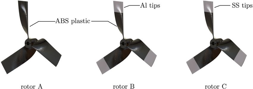
A.M. El Makdah, K. Zhang and D.E. Rival                                             Journal of Fluids and Structures 106 (2021) 103357

developing effective Maximum Power Point Tracking (MPPT) control mechanisms. MPPT control mechanisms ensure that
the wind/tidal turbine operates at its optimal efficiency during varying wind/current speeds by maintaining a constant
tip-speed ratio (λ). Recently, a few MPPT control algorithms that consider the rotor inertia have been proposed (Kim
et al., 2013; Karabacak, 2019). Furthermore, the rotor moment of inertia does not characterize the dynamic response of
rotating systems without taking into consideration their dynamic flow conditions. Thus, this current study introduces a
new normalized inertia number (I ∗ ) to describe the influence of rotor inertia relative to the flow inertia on the performance
of energy-extracting rotor systems operating in unsteady environments. It should be noted that going forward in the
current paper, rotor inertia will be used to refer to the rotor moment of inertia.
    As mentioned previously, many studies have ignored rotor inertia when investigating the behaviour of rotating systems
operating in unsteady environments. For instance, Zhang et al. (2015) investigated the fluid–structure interaction of a
wind-turbine model placed in a microburst-like wind. Despite the fact that their model was dynamically and geometrically
scaled, they did not consider the turbine inertia when scaling their model down. Turbines with higher inertias exhibit
slower responses to changes of the incoming flow. Similarly, several studies on the unsteady behaviour of tidal turbines
have also neglected the turbine’s inertia in their analysis. Milne et al. (2013, 2010, 2015) ignored the rotor inertia when
investigating the unsteady blade loads on tidal turbines in oscillatory flows. Other studies have investigated the influence
of gust and turbulence intensity on the performance of wind-turbine rotors. Lubitz (2014) investigated the effect of
ambient turbulence levels on the energy production of a full-scale small wind turbine through measurements of wind
speed and energy output. Their study found that the increase in turbulence intensity increased energy production at
lower wind speeds. Furthermore, a time lag of up to 2 s was observed between a change of wind speed and the resulting
change in energy output (Lubitz, 2014). More recently, Emejeamara et al. (2015) proposed an analytical model to assess
the available energy present in the gust taken from the turbulence. Their model demonstrates that the available energy
present in the gust is often underestimated by using wind measurements with low temporal resolutions. Moreover, their
results suggest that a wind turbine with a fast response is able to capture the available gust energy. Both Lubitz (2014)
and Emejeamara et al. (2015) do not specify how the turbine physical parameters, especially the rotor inertia, affect the
turbine response per se.
    The unsteady performance of energy-extracting rotor systems is determined by the rotor’s physical size as well as the
density and the velocity of the working fluid. Winter (2011) identified qualitative differences in the unsteady performance
between wind and tidal turbines. It was found that variation in the dynamic response was primarily the result of flow
inertia and the rotor scale. However, to the best of the authors’ knowledge, no study has yet to describe quantitatively
the influence of the rotor inertia on the dynamic performance of energy-extracting rotor systems in unsteady flows.
    The unsteady performance of rotor systems during gusts was investigated experimentally in two recent studies (El
Makdah et al., 2019b,a). In both cases, the gust was modelled as a ramp function of the incoming flow speed, and was
simulated by accelerating a rotor model in a towing-tank facility. The first study (El Makdah et al., 2019a) introduced the
gust duration parameter, denoted by tg∗ (see Eq. (5)). In their study, they reported that low-inertia rotors produce higher
power output during faster gusts (lower tg∗ values). Using time-resolved particle image velocimetry, it was found that
circulatory forces were responsible for the higher power output of low-inertia rotors during these fast gusts. Additionally,
it was found that the tip-speed ratio of their low-inertia rotor model increased rapidly during the gust. Therefore, it was
observed that the rotor model was in fact not operating at its optimal performance point. To address this problem, a
samara-seed inspired rotor utilizing leading-edge vortices (LEVs) was tested (El Makdah et al., 2019b). The samara-seed
inspired rotor was capable of maintaining a steady tip-speed ratio passively during the gust. However, these findings
were limited to low-inertias, and consequently, understanding the influence of rotor inertia on gust response is required
in order to scale up to practical scales.
    The objective of the current study is to introduce and test a new normalized inertia number (I ∗ ) in order to quantify the
influence of rotor inertia on the unsteady response of such rotating systems. I ∗ is derived by normalizing the expression
for rotor unsteady power output during a gust. Experiments are performed in a towing-tank facility to investigate the
influence of the proposed normalized inertia number on the unsteady response of generic rotor systems. Three generic
rotor models with varying inertias are tested. Gust profiles are modelled as ramp functions with varying slopes and are
simulated by accelerating the rotor model in the towing tank. The following section (Section 2) presents the derivation
of the normalized inertia number for energy-extracting rotor systems, while Section 3 presents the experimental setup
used in the current study. The experimental results are then presented and discussed in Sections 4 and 5, respectively.
Finally, the conclusions and outlook are highlighted in Section 6.

2. Normalized inertia number

    In the current study, we introduce the normalized inertia number (I ∗ ) that describes the relationship between the
rotor moment of inertia (I) and the flow inertia. The parametrization used in the current study is illustrated in Fig. 1a. I ∗
is derived by normalizing the expression of the rotor unsteady power output (P) as follows:
                    dΩ
       P = (τ − I         )Ω ,                                                                                                    (1)
                     dt
                                                              2
A.M. El Makdah, K. Zhang and D.E. Rival                                                             Journal of Fluids and Structures 106 (2021) 103357

Fig. 1. (a) Schematic of rotor response during the gust showing the parametrization used in the current study. CP , λ, U∞ , and tg∗ are the coefficient
of power, tip-speed ratio, flow speed, and gust duration, respectively. The subscripts i and f refer to the initial and final steady parameters before
and after the gust, respectively. (b) Schematic of dynamic response of geometrically-similar rotors with varying normalized inertia number (I ∗ ).

where τ , Ω , I, and t are the rotor torque, speed, inertia, and dimensional time, respectively. The rotor power and speed
are normalized using the following expressions,
                         P
       CP =                      ,                                                                                                                 (2)
                1
                2
                    ρ U∞
                       3 π R2

               ΩR
       λ=            ,                                                                                                                             (3)
               U∞
where CP , λ, ρ , U∞ , and R are the coefficient of power, tip-speed ratio, flow density, instantaneous incoming flow speed,
and rotor radius, respectively. Similar to previous studies (El Makdah et al., 2019b,a), the dimensional time (t) and gust
acceleration (a) are normalized using the following expressions,
                (Uf − Ui )
       t∗ = t                ,                                                                                                                     (4)
                         D

               1 (Uf − Ui )2
       tg∗ =                   ,                                                                                             (5)
               a        D
where t ∗ , tg∗ , Ui , Uf , and D are the dimensionless time, gust duration, initial flow speed, final flow speed, and the rotor
diameter, respectively. Writing Eq. (1) in terms of the dimensionless parameters (Eqs. (2)–(5)) gives
                2            2                   U∞      dλ
       CP =         τ ∗λ −       I ∗ [tg∗ λ                     + λ2 ],                                                                            (6)
                π            π                (Uf − Ui ) dt ∗
where
                     a
       I∗ = I                                                                                                                                      (7)
                ρ R4 U∞
                      2

is the normalized inertia number, and
                   τ
       τ∗ =                                                                                                                                        (8)
                ρ R3 U∞
                      2

is the normalized torque.
    The second term on the right-hand side of Eq. (6) is the unsteady term responsible for lowering the coefficient of power
(CP ) of the rotor system during the gust. I ∗ dictates the strength of this unsteady term. Thus low I ∗ , as in the case of low-
inertia rotors, alleviates the impact of the unsteady effect on the rotor efficiency. On the other hand, high-inertia rotors
(high I ∗ ) are expected to operate at a lower efficiency during the gust, as shown in Fig. 1b. Table 1 lists the normalized
inertia number (I ∗ ) for different commercial small wind turbines.
                                                                          3
A.M. El Makdah, K. Zhang and D.E. Rival Journal of Fluids and Structures 106 (2021) 103357
Table 1
Normalized inertia number (I ∗ ) for various small wind turbines of different sizes experiencing different wind speeds
(U∞ ) and an acceleration (a) of 1 m/s2 . The wind turbines data are taken from Tang et al. (2008).
D (m) Prated [kW] I [kg m2 ] I ∗ × 10−3 [–] (U∞ = 6 m/s) I ∗ × 10−3 [–] (U∞ = 10 m/s)
1.15 0.4 0.026 5.393 1.942
3.70 3.0 5.550 10.744 3.868
5.10 5.5 24.270 13.016 4.656
6.20 10.0 59.610 14.636 5.269
10.40 20.0 643.710 19.964 7.187
Table 2
The mass (m) and physical inertia (I) of the rotor models tested in the current study.
Rotor m [g] I [kg m2 ]
A 82.8 4.9 × 10⁻⁴
B 113.2 9.6 × 10⁻⁴
C 208.9 24.3 × 10⁻⁴
Fig. 2. The rotor models used in the current study. Rotor A is 3D-printed entirely out of ABS plastic. The bases of rotors B and C are also 3D-printed
out of ABS plastic, while their tips were machined out of Aluminium (Al) and Stainless Steel (SS), respectively.
3. Experimental setup
Three generic rotor models with differing inertias were used to investigate the influence of the normalized inertia
number on the rotor dynamic response during gusts. The three rotor models are labelled ‘‘A’’, ‘‘B’’, and ‘‘C’’ (Fig. 2). Rotor
A was entirely 3D-printed out of Acrylonitrile Butadiene Styrene (ABS) plastic with a printing resolution of 0.127 mm. The
bases of rotors B and C were also 3D-printed out of ABS plastic, while their tips were machined out of Aluminium (Al)
and Stainless Steel (SS), respectively. The rotor models each have a diameter of 30 cm producing a blockage ratio of 7.1%,
based on swept area, in the towing tank. The blades of the rotors were designed to have a constant chord, an aspect ratio
(AR) of 3, and a constant SD7003 airfoil profile. The airfoil profile SD7003 was chosen because its lift and drag coefficients
are independent of Reynolds number, based on chord of 5 cm, over the range of 60,000 < Re < 300,000. Furthermore,
the blades were designed with twist to produce a constant spanwise effective angle of attack of 10◦ at a tip-speed ratio
(λ) of 4. It should be noted that modern horizontal-axis wind turbines operate at tip-speed ratios of 4 ≤ λ ≤ 8 (Burton
et al., 2001). Tidal turbines, however, often operate at tip-speed ratios in the range of 3 ≤ λ ≤ 8 (Milne et al., 2013;
Sequeira and Miller, 2014; Birjandi et al., 2013; Luznik et al., 2013). The inertia and mass of each rotor model are listed
in Table 2.
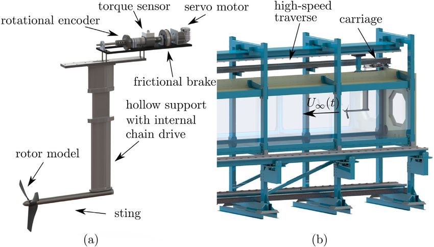
A rotor rig, shown in Fig. 3a, was used to examine the unsteady response of the three rotor models. The model was
installed at the end of the sting, and the rotor rotation is transmitted to a sensor assembly via a 1:1 chain drive. The
speed and torque of the rotor model were recorded by a magnetic encoder (Baumer⃝ R
ITD69H00) and torque sensor
(HBM⃝ R
T22), respectively. Both sensors were sampled at a frequency of 1 kHz. Moreover, a servo motor (ClearPath⃝ R
CPM-MCVC-2311S-RQN) was used to help start the rotor models at the beginning of each test run. A constant load was
applied to the rotor models using a frictional brake to achieve a tip-speed ratio (λ) of 4 before the start of the gust.
All experiments were performed in a 15-m long optical towing tank at Queen’s University. The towing tank has a 1 m
× 1 m cross-section and is enclosed by a ceiling along its length to minimize free-surface effects. The ceiling has a 50-mm
wide opening in which the model support can pass, as shown in Fig. 3b. The rotor rig was mounted such that its axis
of rotation is aligned with the tank’s centre axis. In the current study, gusts are modelled as ramp functions of the wind
speed, and they are modelled by accelerating the rotor model from a steady initial speed to a steady final speed. Four gust
4A.M. El Makdah, K. Zhang and D.E. Rival Journal of Fluids and Structures 106 (2021) 103357
Fig. 3. (a) Schematic of the experimental rig depicting the rotor model and the sensor assembly. (b) Schematic of the experimental rig installed in
the towing-tank facility.
Fig. 4. Gust profiles tested in the current study. The plots show the gust profiles tested for (a) Sets 1, 2, and (b) Set 3 in the test matrix (Table 3).
profiles (tg∗ = 0.5, 1, 2, 4), as shown in Fig. 4, are tested in the current study. These four profiles have been selected based
on previous experience of investigating the dynamic response of rotor systems (El Makdah et al., 2019b,a). Furthermore,
the experiments and the rotors were designed to keep the effective angle of attacks below the stall angles during the
gust. Initially, the rotor was towed with an initial steady towing speed (Ui ) for at least four units of the dimensionless
time (t ∗ ) before the start of the gust. For each experiment case, the recorded rotor speed and torque were averaged over
20 independent test runs. The measurement accuracy of CP was estimated to be 0.48% at a 95% confidence level.
3.1. Test matrix
Three sets of experiments, summarized in Table 3, were performed to investigate the influence of the normalized
inertia number (I ∗ ) on the rotor unsteady performance during gusts. The test matrix was designed to examine rotors
with a range of I ∗ that is equivalent to typical commercial small wind turbines listed in Table 1. The experiments from
Set 1 were chosen to examine the unsteady performance of the rotor models during gust profiles with different gust
intensities (tg∗ ) and the same initial (Ui ) and final (Uf ) flow speeds. In Set 2, I ∗ and tg∗ were held constant for each rotor
model while changing the initial gust speed (Ui ). The purpose of Set 2 is specifically to test whether the rotor dynamic
response remains unchanged when holding I ∗ constant. Moreover, the experiments of Set 3 were chosen to investigate the
effect of increasing I ∗ on the unsteady performance of the rotor models while maintaining a similar tg∗ and dimensional
5A.M. El Makdah, K. Zhang and D.E. Rival Journal of Fluids and Structures 106 (2021) 103357
Table 3
The test matrix used in the current study. Ii∗ is the initial normalized inertia number at the start of the gust.
Set tg∗ Ui [m/s] Uf [m/s] a [m/s2 ] Ii∗,A × 10−3 Ii∗,B × 10−3 Ii∗,C × 10−3
0.5 1.0 1.5 1.67 1.6 3.2 8.0
1.0 1.0 1.5 0.83 0.8 1.6 4.0
1
2.0 1.0 1.5 0.42 0.4 0.7 2.0
4.0 1.0 1.5 0.21 0.2 0.4 1.0
0.5 1.0 1.5 1.67 1.6 3.2 8.0
2 0.5 0.8 1.2 1.07 1.6 3.2 8.0
0.5 0.6 0.9 0.60 1.6 3.2 8.0
0.5 1.0 1.5 1.67 1.6 3.2 8.0
3 0.5 0.8 1.3 1.67 2.5 4.9 12.0
0.5 0.6 1.1 1.67 4.5 8.7 22.0
Fig. 5. Instantaneous tip-speed ratio (λ) for rotors A, B, and C during gust tg∗ = 0.5 with initial and final flow speeds of (a) Ui = 1 m/s and Uf = 1.5
m/s, (b) Ui = 0.8 m/s and Uf = 1.2 m/s, and (C) Ui = 0.6 m/s and Uf = 0.9 m/s (Set 2). Ii∗ is the initial normalized inertia number at the start of
the gust.
acceleration (a). The model towing speeds are increased by 50% during each experiment for Sets 1 and 2 (Fig. 4a), while
the towing speeds are increased by 0.5 m/s in Set 3 (Fig. 4b).
4. Results
The normalized inertia number (I ∗ ) is the ratio of the rotor inertia to the flow inertia. Three geometrically-similar rotor
models with varying inertias were tested to examine the influence of I ∗ on the unsteady performance of rotor systems.
The initial tip-speed ratio (λi ), before the gust, was maintained at 4 for all test cases. The measured λ during the gust
6A.M. El Makdah, K. Zhang and D.E. Rival Journal of Fluids and Structures 106 (2021) 103357
Fig. 6. Instantaneous coefficient of power (CP ) for rotors A, B, and C during different profiles of gust with initial flow speed (Ui ) of 1 m/s and final
flow speed (Uf ) of 1.5 m/s (Set 1). Ii∗ is the initial normalized inertia number at the start of the gust. Since Ii∗ is low during the slow profiles of
gust (tg∗ = 2) and (tg∗ = 4), the rotor inertia does not influence the unsteady power output.
(tg∗ = 0.5) is plotted in Fig. 5. As mentioned earlier, the main objective of the current study is to test whether the rotor
normalized inertia number (I ∗ ), rather than the physical inertia, describes the rotor’s ability to extract the energy present
in the gust.
Fig. 6 shows the instantaneous coefficient of power (CP ) for the three rotor models during gust profiles (tg∗ =
0.5, 1, 2, 4) presenting the results of Set 1 of the test matrix (Table 3). During the fast gust profiles (tg∗ = 0.5) and (tg∗ = 1),
rotor C had a lower CP than rotors A and B. As the flow acceleration (a) decreases (tg∗ increases), I ∗ of the rotor models
decreases as well. As a result, the three rotors exhibited similar performances during the slower gust profiles (tg∗ = 2)
and (tg∗ = 4), as shown in Fig. 6c and d. Therefore, the effect of inertia on the dynamic response became less significant
(non-existent in this case) at lower I ∗ .
Fig. 7 shows the results of the experiments of Set 2 and plots the instantaneous coefficient of power (CP ) of the three
rotors during the gust (tg∗ = 0.5) with initial flow speeds (Ui ) of 0.6 m/s, 0.8 m/s, and 1 m/s. In Set 2, I ∗ for the three
rotors was held constant while varying the initial incoming flow speed (Ui ) of the tested gust profiles with the same gust
intensity (tg∗ ). Rotor B had slightly lower power output during the gust than rotor A, while rotor C produced the lowest
power output during all the tested gust profiles of Set 2.
To test the influence of I ∗ on the dynamic response, we increased I ∗ in Set 3 for the rotor models by decreasing the
flow speed while keeping the flow acceleration (a) and gust intensity (tg∗ ) constant. Fig. 8 plots the results of Set 3 and
shows the instantaneous coefficient of power of the three rotors during gust profile (tg∗ = 0.5) with initial flow speeds
(Ui ) of 0.6 m/s, and 0.8 m/s. The influence of the rotors inertia became more significant by increasing I ∗ ; thus, rotors A
and B exhibited clearly different dynamic responses due to their different physical inertias. Rotor C remained to produce
lower normalized power output than rotors A and B due to its normalized inertia number.
7A.M. El Makdah, K. Zhang and D.E. Rival Journal of Fluids and Structures 106 (2021) 103357
Fig. 7. Instantaneous coefficient of power (CP ) for rotors A, B, and C during gust tg∗ = 0.5 with initial and final flow speeds of (a) Ui = 1 m/s and
Uf = 1.5 m/s, (b) Ui = 0.8 m/s and Uf = 1.2 m/s, and (C) Ui = 0.6 m/s and Uf = 0.9 m/s (Set 2). Ii∗ is the initial normalized inertia number at the
start of the gust.
5. Discussion
Most previous studies have ignored rotor inertia when studying the performance of wind and tidal turbines operating
in unsteady environments. For example, Zhang et al. (2015) used a lab-scale wind-turbine model to investigate the wind
loads acting on a wind turbine experiencing microburst-like winds. However, the inertia of the rotor does not determine
by itself the dynamic response of the rotating system without taking into consideration the flow inertia. Therefore, the
current study introduces the normalized inertia number (I ∗ ) as a key dimensionless group to consider when scaling the
lab-scale rotors or when extrapolating to other scales. I ∗ describes the impact of the rotor moment of inertia relative to
the flow inertia on the unsteady performance of the rotor system operating in unsteady environments.
It was expected that a rotor would exhibit the same dynamic response for different gust profiles and with varying
inflow speeds but the same gust duration so long I ∗ was held constant. Fig. 9 plots the instantaneous normalized coefficient
of power ((CP − CPi )/CPi ) during the gust tg∗ = 0.5 for initial inflow speeds (Ui ) of 0.6 m/s, 0.8 m/s, and 1 m/s for the three
rotor models. Each rotor model exhibited similar unsteady performance during all gust profiles with varying Ui . As a result,
the rotor’s ability to extract the energy present in the gust remains unaffected by varying the gust initial flow speed (Ui )
so long as the rotor I ∗ is held constant.
It is commonly accepted that rotor inertia influences unsteady performance during a gust. However, establishing the
inertia of a given rotor alone does not allow one to predict the rotor’s dynamic response. Instead, one needs to have
information on the rotor inertia relative to the flow inertia (e.g. flow acceleration); in other words, the rotor normalized
inertia number (I ∗ ). Fig. 10 shows the instantaneous normalized coefficient of power ((CP − CPi )/CPi ) of the results of Set 3.
The influence of the rotor inertia becomes less significant by decreasing I ∗ ; thus, the rotor produces higher power output
during the gust. In conclusion, Figs. 9 and 10 show that the rotor normalized inertia number (I ∗ ), and not its physical
inertia (I), determines the ability of the rotor system to extract the available gust energy.
8A.M. El Makdah, K. Zhang and D.E. Rival Journal of Fluids and Structures 106 (2021) 103357
Fig. 8. Instantaneous coefficient of power (CP ) for rotors A, B, and C during gust tg∗ = 0.5 with initial and final flow speeds of (a) Ui = 0.8 m/s and
Uf = 1.3 m/s, and (b) Ui = 0.6 m/s and Uf = 1.1 m/s (Set 3). Ii∗ is the initial normalized inertia number at the start of the gust.
Fig. 9. Instantaneous normalized coefficient of power ((CP − CPi )/CPi ) of rotors A, B and C during gust tg∗ = 0.5 with different initial speeds (Set
2). The gust starts and ends at t ∗ = 0 and t ∗ = 0.5, respectively. Ii∗ is the initial normalized inertia number at the start of the gust, and was held
constant for each rotor model while changing the initial gust speed (Ui ). Rotors with the same I ∗ exhibited similar dynamic responses during the
gust.
9A.M. El Makdah, K. Zhang and D.E. Rival Journal of Fluids and Structures 106 (2021) 103357
Fig. 10. Instantaneous normalized coefficient of power ((CP − CPi )/CPi ) of rotors A, B and C during gust profile (tg∗ = 0.5) with different initial speeds
(Set 3). The gust starts and ends at (t ∗ = 0) and (t ∗ = 0.5), respectively. Ii∗ is the initial normalized inertia number at the start of the gust, and
it was increased for each rotor model by reducing the initial gust speed (Ui ). Rotors with higher I ∗ captured less gust energy regardless of their
physical inertias.
Fig. 11. The maximum normalized coefficient of power ((CPmax − CPi )/CPi ) during gust profile (tg∗ = 0.5) versus the normalized inertia number (I ∗ ).
Rotors with lower I ∗ captured higher gust energy regardless of their physical inertias.
In a previous study, El Makdah et al. (2019a) showed that low-inertia rotors produce higher power output during fast
gusts when compared to quasi-steady operation. In the current study, we show that the rotor inertia by itself does not
determine the ability of the rotor to extract the gust energy. Instead, both rotor inertia and (changes in) flow inertia, in
addition to gust duration (tg∗ ), determine the power output of the rotating system. Fig. 11 plots the maximum normalized
coefficient of power ((CPmax − CPi )/CPi ) during the gust tg∗ = 0.5 versus I ∗ . This figure shows that a rotating system with
sufficiently low I ∗ will extract more energy during fast gusts than for quasi-steady operation regardless of the rotor’s
physical inertia. However, the findings of the current study do not necessarily suggest that rotors with the lowest I ∗ are
the optimal rotors for all applications. The choice of optimal I ∗ depends on the end application of the rotor system. For
example, the sudden increase in the power output during the gust might strain the battery storage system if this power
output variation is not accounted for in sizing the storage system. While the previous study by El Makdah et al. (2019a)
introduced the definition of a gust duration (tg∗ ) as an important parameter that affects the performance of rotor systems
during gusts, the current study establishes the normalized inertia number (I ∗ ) that affects the unsteady rotor’s performance.
The findings of the current study, along with previous work (El Makdah et al., 2019a), provide a framework to analyse
the unsteady performance of energy-extracting rotor systems, which is crucial for developing effective Maximum Power
Point Tracking (MPPT) control mechanisms for rotor systems such as wind and tidal turbines.
10A.M. El Makdah, K. Zhang and D.E. Rival Journal of Fluids and Structures 106 (2021) 103357
6. Conclusions
The current study presents a new normalized inertia number (I ∗ ) to describe the influence of the rotor moment of
inertia, relative to the (change in) flow inertia, on the system’s overall unsteady response during a gust. The unsteady
performance of three rotor models were examined experimentally, using a towing-tank facility, to test the influence of the
normalized inertia number (I ∗ ) on rotor performance. We designed rotor models that were geometrically and dynamically
identical, but with varying moments of inertia (weighted blade tips). Gust profiles were modelled as ramp functions of
the incoming flow speed with differing slopes.
In the current study, it is shown that the rotor moment of inertia (I) cannot in itself characterize the behaviour of
rotating systems during the gust. Instead, the rotor normalized inertia number determines the unsteady performance of
the rotating system during a gust for a given gust duration (tg∗ ). Rotor systems were found to produce less power during
the gust as I ∗ was systemically increased. Furthermore, increasing I ∗ by reducing the flow inertia – by decreasing the flow
speed, for example – was found to amplify the effect of rotor inertia on the system’s overall performance. For instance,
the normalized power output during the gust of rotor B was 30% higher during the gust than for steady operation, when
I ∗ = 3.2 × 10⁻³ . However, the normalized power output of rotor B during the gust was 19% higher than for steady
operation, when I ∗ increased to 8.7 × 10⁻³ .
Investigating the behaviour of rotors in unsteady environments is essential to design micro aerial vehicles, quad-rotors,
wind and tidal turbines, and other rotor systems that operate in unsteady environments. Previous studies identified the
gust duration (tg∗ ) as an important parameter that influences the rotor performance during the gust. This study introduces
the normalized inertia number (I ∗ ) as a more appropriate parameter that affects the unsteady rotor performance. Finally,
this study also provides a potential framework to investigate the flight of autorotating systems such as maple seeds, in
turn providing insight into their evolution and scaling.
CRediT authorship contribution statement
Adnan M. El Makdah: Conceptualization, Methodology, Validation, Investigation, Resources, Writing – original draft,
Writing – review & editing, Visualization. Kai Zhang: Conceptualization, Writing – review & editing, Supervision. David
E. Rival: Conceptualization, Writing – review & editing, Supervision, Funding acquisition.
Declaration of competing interest
The authors declare that they have no known competing financial interests or personal relationships that could have
appeared to influence the work reported in this paper.
Acknowledgements
This work was supported by NSERC CREATE Sustainable Engineering in Remote Areas (SERA), Canada, and DER’s NSERC
Discovery Grant, Canada.
References
Birjandi, A.H., Bibeau, E.L., Chatoorgoon, V., Kumar, A., 2013. Power measurement of hydrokinetic turbines with free-surface and blockage effect.
Ocean Eng. 69, 9–17. http://dx.doi.org/10.1016/j.oceaneng.2013.05.023.
Boukhezzar, B., Lupu, L., Siguerdidjane, H., Hand, M., 2007. Multivariable control strategy for variable speed, variable pitch wind turbines. Renew.
Energy 32 (8), 1273–1287. http://dx.doi.org/10.1016/j.renene.2006.06.010.
Burton, T., Sharpe, D., Jenkins, N., Bossanyi, E., 2001. Wind Energy Handbook. John Wiley & Sons, Ltd, http://dx.doi.org/10.1002/0470846062.
El Makdah, A.M., Ruzzante, S., Zhang, K., Rival, D.E., 2019a. The influence of axial gusts on the output of low-inertia rotors. J. Fluids Struct. 88, 71–82.
http://dx.doi.org/10.1016/j.jfluidstructs.2019.04.009.
El Makdah, A.M., Sanders, L., Zhang, K., Rival, D.E., 2019b. The stability of leading-edge vortices to perturbations on samara-inspired rotors: a novel
solution for gust resistance. Bioinspir. Biomim. 15 (1), 016006. http://dx.doi.org/10.1088/1748-3190/ab5549.
Elghali, S.B., Benbouzid, M., Charpentier, J., Ahmed-Ali, T., Gahery, J., Denis, A., 2008. Modeling and MPPT sensorless control of a DFIG-based marine
current turbine. In: 2008 18th International Conference on Electrical Machines. IEEE, http://dx.doi.org/10.1109/icelmach.2008.4800165.
Emejeamara, F., Tomlin, A., Millward-Hopkins, J., 2015. Urban wind: Characterisation of useful gust and energy capture. Renew. Energy 81, 162–172.
http://dx.doi.org/10.1016/j.renene.2015.03.028.
Ghefiri, K., Bouallegue, S., Haggege, J., Ghefiri, K., Garrido, I., Garrido, A.J., 2017. Modeling and MPPT control of a tidal stream generator. In: 2017 4th
International Conference on Control, Decision and Information Technologies (CoDIT). IEEE, http://dx.doi.org/10.1109/codit.2017.8102730.
Karabacak, M., 2019. A new perturb and observe based higher order sliding mode MPPT control of wind turbines eliminating the rotor inertial effect.
Renew. Energy 133, 807–827. http://dx.doi.org/10.1016/j.renene.2018.10.079.
Kim, K.-H., Van, T.L., Lee, D.-C., Song, S.-H., Kim, E.-H., 2013. Maximum output power tracking control in variable-speed wind turbine systems
considering rotor inertial power. IEEE Trans. Ind. Electron. 60 (8), 3207–3217. http://dx.doi.org/10.1109/tie.2012.2200210.
Leishman, J.G., 2002. Challenges in modelling the unsteady aerodynamics of wind turbines. Wind Energy 5 (2–3), 85–132. http://dx.doi.org/10.1002/
we.62.
Lubitz, W.D., 2014. Impact of ambient turbulence on performance of a small wind turbine. Renew. Energy 61, 69–73.
Luznik, L., Flack, K.A., Lust, E.E., Taylor, K., 2013. The effect of surface waves on the performance characteristics of a model tidal turbine. Renew.
Energy 58, 108–114. http://dx.doi.org/10.1016/j.renene.2013.02.022.
11A.M. El Makdah, K. Zhang and D.E. Rival Journal of Fluids and Structures 106 (2021) 103357
Milne, I., Day, A., Sharma, R., Flay, R., 2013. Blade loads on tidal turbines in planar oscillatory flow. Ocean Eng. 60, 163–174. http://dx.doi.org/10.
1016/j.oceaneng.2012.12.027.
Milne, I., Day, A., Sharma, R., Flay, R., 2015. Blade loading on tidal turbines for uniform unsteady flow. Renew. Energy 77, 338–350. http:
//dx.doi.org/10.1016/j.renene.2014.12.028.
Milne, I., Sharma, R., Flay, R., Bickerton, S., 2010. The role of onset turbulence on tidal turbine blade loads. In: Proc. 17th Australasian Fluid Mechanics
Conference, Auckland, NZ.
Rahman, M.L., Oka, S., Shirai, Y., 2010. Hybrid power generation system using offshore-wind turbine and tidal turbine for power fluctuation
compensation (HOT-PC). IEEE Trans. Sustain. Energy 1 (2), 92–98. http://dx.doi.org/10.1109/tste.2010.2050347.
Ran, L., Bumby, J., Tavner, P., 2004. Use of turbine inertia for power smoothing of wind turbines with a DFIG. In: 2004 11th International Conference
on Harmonics and Quality of Power (IEEE Cat. No.04EX951), IEEE, http://dx.doi.org/10.1109/ichqp.2004.1409337.
Scelba, G., Consoli, A., 2010. Gust tracking capability of small direct-drive wind turbines. In: 2010 IEEE International Conference on Sustainable Energy
Technologies (ICSET). IEEE, http://dx.doi.org/10.1109/icset.2010.5684963.
Sequeira, C.L., Miller, R.J., 2014. Unsteady gust response of tidal stream turbines. In: OCEANS 2014 - St. John’s. IEEE, http://dx.doi.org/10.1109/oceans.
2014.7003026.
Tang, C., Pathmanathan, M., Soong, W.L., Ertugrul, N., 2008. Effects of inertia on dynamic performance of wind turbines. In: 2008 Australasian
Universities Power Engineering Conference. pp. 1–6.
Winter, A.I., 2011. Differences in fundamental design drivers for wind and tidal turbines. In: OCEANS 2011 IEEE - Spain. IEEE, http://dx.doi.org/10.
1109/oceans-spain.2011.6003647.
Zhang, Y., Sarkar, P.P., Hu, H., 2015. An experimental investigation on the characteristics of fluid–structure interactions of a wind turbine model sited
in microburst-like winds. J. Fluids Struct. 57, 206–218. http://dx.doi.org/10.1016/j.jfluidstructs.2015.06.016.
12You can also read


