JT-60SA TOROIDAL FIELD COIL QUENCH MODEL AND ANALYSIS: ITER ...
←
→
Page content transcription
If your browser does not render page correctly, please read the page content below
JT-60SA TOROIDAL FIELD COIL QUENCH MODEL AND ANALYSIS:

 JOULE ENERGY ESTIMATION WITH SUPERMAGNET AND STREAM
 Quentin GORIT
 IUSTI/ PT/ IPT
 CEA / DRF / IRFM / STEP / GAIM

 Q. GORIT, F. TOPIN, S. NICOLLET, A. LOUZGUITI,
 DE LA RECHERCHE À L’INDUSTRIE B. LACROIX, A. TORRE, R. VALLCORBA, L. ZANI

 20/09/2021

 Commissariat à l’énergie atomique et aux énergies alternatives - www.cea.fr
Commissariat à l’énergie atomique et aux énergies alternatives

CONTENT

 1) Introduction

 2) Normal length estimation from voltage measurement

 3) Numerical and analytical quench models

 4) JT-60SA TFC02 acceptance quench test in Cold Test Facility analysis

 5) JT-60SA TFC quench in Tokamak environment: predictive calculation

 6) Conclusion

Commissariat à l’énergie atomique et aux énergies alternatives PhD Q. Gorit: CHATS 2021 Presentation, 20/09/2021 2
1.1) JT-60SA TF COIL AND QUENCH IN CICC Copper matrix 22 mm 0,8 mm 26 mm Central DP ≈8 m Inner DP Side DP NbTi filaments Strand CICC (Cable-In-Conduit-Conductor) cooled by supercritical helium forced-flow WP (Winding Pack) TFC (Toroidal Field Coil) Quench: Irreversible transition from superconducting state to normal resistive state. If not quickly detected, it may lead to possible permanent damage of the magnet. Starting from a local perturbation, the normal (quenched) zone propagates and generates a large resistive power by Joule effect. He inlet He outlet 3 113 m Commissariat à l’énergie atomique et aux énergies alternatives PhD Q. Gorit: CHATS 2021 Presentation, 20/09/2021 3
1.2) JT-60SA TFC QUENCH TESTS IN COLD TEST FACILITY (SACLAY, 2016-2018) 18 TF coils and 2 spare coils were tested for: 0.05 K/min Acceptance tests before delivery Quench moment Quench phenomenon investigations 0.4 K/min Inlet quench initiation by Pick-up coil increasing the injected helium temperature Joints and helium inlets box Helium temperatures at Winding Pack inlet and outlet JT-60SA TFC in Cold Test Facility Commissariat à l’énergie atomique et aux énergies alternatives PhD Q. Gorit: CHATS 2021 Presentation, 20/09/2021 4
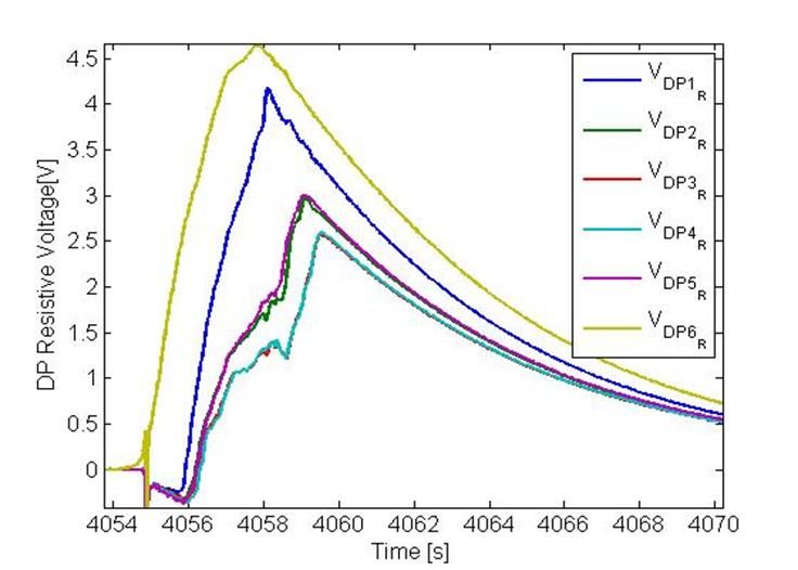
2.1) RESISTIVE VOLTAGE ESTIMATION FROM VOLTAGE MEASUREMENTS

 Cold Test Facility instrumentation allows to study the quench propagation Resistive and inductive voltage determination
 and the resulting helium expulsed mass flow from the coil.
 Pure Current Fast Discharge (PCFD) test (without quench ( ) =0 Ω) was
 used in order to estimate inductive voltage induced in TFC02 double-pancakes.

 , ( ) , ( )
 ( ) = =
 ( ) ( )
 ℎ

 Application to TFC02 acceptance quench test
 ( 0 = 25.7 kA, = 3.05 T, ṁ = 24 g/s, = 0.1 s, = 8 s)

 Cold Test facility instrumentation scheme

 The fast current discharge decreases magnetic field which induce inductive
 voltage inside coil and passive structures.

 ( )
 , = + + ( )

 , ,

 Inductive voltage due to the mutual inductance between coil and passive structures
 ( ൯
 were estimated negligeables ( ≅ 0 V) using an analytical method. TFC02 acceptance quench test, double-pancake resistive voltages (Exp)

 [1] A.Louzguiti et al., ‘Modeling of AC losses and simulation of their impact on JT-60SA TF magnets during commissioning’, ASC Conference, 2020

Commissariat à l’énergie atomique et aux énergies alternatives PhD Q. Gorit: CHATS 2021 Presentation, 20/09/2021 5
2.2) NORMAL LENGTH ESTIMATION FROM RESISTIVE VOLTAGE Heuristic quench propagation model for normal length estimation Experimental pancake resistance assumption: ( ) , ( ) ( ) = = 2 ( ) Maximal conductor temperature calculation: , ( ) Initial condition: , = 0 = 0-D energy conservation relations applied to helium, conductor and jacket Linear temperature profile assumption: Boundary condition: , = 0 = , ( ) , − , = Predicted and measured resistances comparison Schematic of the heuristic quench propagation model CICC normal length evolution at each time step [2] Y. Huang, ‘Study and modelling of the thermohydraulic phenomena taking place during the quench of a superconducting magnet cooled with supercritical helium’, p. 179, 2019 Commissariat à l’énergie atomique et aux énergies alternatives PhD Q. Gorit: CHATS 2021 Presentation, 20/09/2021 6
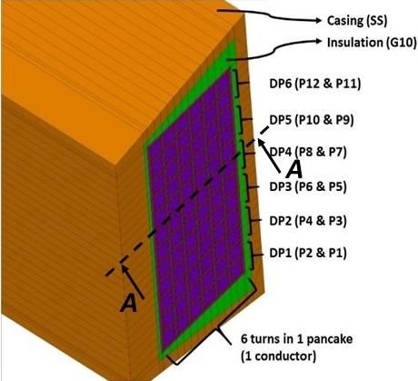
3.1) TF COIL AND CRYODISTRIBUTION SUPERMAGNET MODEL SuperMagnet code (L. Bottura ,CERN, fortran): Coupling THEA (1-D CICC electrical and thermohydraulical model) and FLOWER (hydraulical model) FLOWER modelisation of the cryodistribution THEA modelisation of 12 CICC with helium, strands and jacket components (pump, heat exchanger, quench relief tank, valves and heater) Magnetic field profile (TRAPS) and friction factor correlation (OTHELLO facility) for each pancake , 1 3 NbTi/Cu strands ℎ = 8 ℎ SS jacket ℎ G10 insulation 1− 2 = ℎ Quench primary detection: voltage threshold = 0.1 V Current discharge ( ( ) = 0 − / ) triggers after quench detection and action time ( = 0.1 s) Developed numerical SuperMagnet model of JT-60SA TF coil and its cryodistribution Schematic of TFC and cryodistribution SuperMagnet model [3] S. Nicollet and al., ‘Parametric Analyses of JT-60SA TF Coils in the Cold Test Facility With SuperMagnet Code’, IEEE Trans. Appl. Supercond., vol. 28, no. 3, p. 4205205, Apr. 2018. Commissariat à l’énergie atomique et aux énergies alternatives PhD Q. Gorit: CHATS 2021 Presentation, 20/09/2021 7
3.2) ANALYTICAL STREAM MODEL
 STREAM: Superconductor Thermohydraulical and Resistive Electrical Analytical Model
 (S. Nicollet, IRFM, Matlab):
 Thermohydraulical governing equations:
 0-D adiabatic cold volume submitted to isentropic compression:
 ℎ
 = − =

 0-D energy conservation relations applied to conductor, helium and jacket:
 ( ) ( )
 ( ) ( )2 − ℎ , ( ) − ( )

 =
 ( ) + ( )

 Second law of thermodynamics, energy and mass conservative relations describe the
 1-D expulsed helium flow from the coil when reaching a pressure drop threshold.
 STREAM model scheme
 A. Shajii analytical quench propagation model: Long coil - High pressure rise Regime
 1 2
 Δ 0 0 02 , 2 ℎ 5 , 0 02 5 1
 = >1 = = 0.766 1
 0 2 0 0
 5
 24 ℎ 02
 2 > 0 = min ( )
 ( ) =[ :300] +

 [4] A. Shajii, J. P. Freidberg, and E. A. Chaniotakis, ‘Universal scaling laws for quench and thermal hydraulic
 quenchback in CICC coils’, IEEE Transactions on Applied Superconductivity, vol. 5, no. 2, pp. 477–482, Jun. 1995

Commissariat à l’énergie atomique et aux énergies alternatives PhD Q. Gorit: CHATS 2021 Presentation, 20/09/2021 8
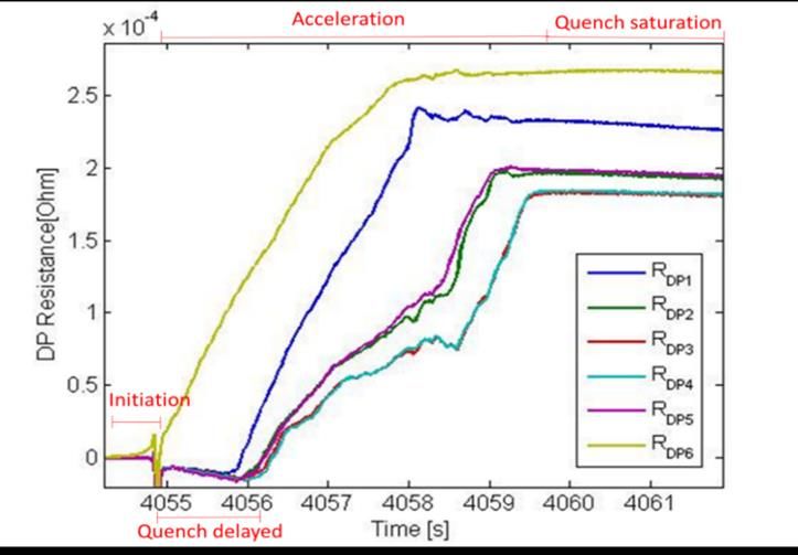
4.1) TFC02 ACCEPTANCE TEST: QUENCH PROPAGATION , 1, = , 12, = 22.5 m/s , 12, = = 25.6 m/s 39 m , , = = 17.4 m/s 19 m , = = 16.1 m/s TFC02 acceptance quench test, double-pancake resistance (Exp) TFC02 acceptance quench test, normal length propagation (SM , STREAM, Exp) Central DP Quench initiation at inlet of side double-pancake 6 caused by the thermal loss from thick casing to Winding Pack Inner DP Helium reverse flow effect: warm helium injection (expulsed mass flow from side pancake) Side DP simultaneous quench initiation in inner and central double-pancakes Quench propagation mitigated by V-shape magnetic field distribution: , 6, = 16.2 m/s < , 10, = 17.4 m/s < , 12, 19 m 39 m Re-acceleration phenomenon: Second quench initiation in inner and central double- pancakes ( ≅50 m/s) by a quench propagating through electrical inter-pancake joints TFC02 acceptance quench test, Magnetic field and current sharing temperature profiles Commissariat à l’énergie atomique et aux énergies alternatives PhD Q. Gorit: CHATS 2021 Presentation, 20/09/2021 9
4.2) TFC02 ACCEPTANCE TEST : ELECTRICAL RESULTS TFC02 acceptance quench test, coil resistive voltage (SM, STREAM, Exp) TFC02 acceptance quench test, coil Joule energy dissipation (SM, STREAM, Exp) , , = 14.9 V < , , = 17. 3 V < , , = 17.8 V , = 1.64 MJ < , = . < , = 2.21 MJ = = ( ൯ Good agreement between experimental, analytical and numerical , = = න න , 2 results. =1 =1 0 0 STREAM is conservative, indeed the model extrapolates results from , , = , = 2.20 MJ one CICC to the twelve composing the coil. Commissariat à l’énergie atomique et aux énergies alternatives PhD Q. Gorit: CHATS 2021 Presentation, 20/09/2021 10
4.3) TFC02 ACCEPTANCE TEST : THERMOHYDRAULICAL RESULTS , , = 32.58 K , , , = 27.12 K , , , = 26.77 K , , = , , = 0.5 kg/s TFC02 acceptance quench test, helium and conductor temperatures (SM, STREAM, Exp) TFC02 acceptance quench test, helium mass flows (SM, STREAM, Exp) Normal zone induces local helium depletion and high forced convection expulsing helium mass flows in two opposite directions (reverse and accelerate mass flows) Quench detection time (t=4055 s): Helium inlet and outlet valves are closed (quasy isochoric system) 5 s period (t=4060 s) : Quench safety valves opening (releasing the warmed helium from the coil into the quench tank) The maximal conductor temperature calculated numerically reach 32.58 K in the side pancake 12 (first pancake reaching the quench saturation phase) Cold Test facility instrumentation scheme Commissariat à l’énergie atomique et aux énergies alternatives PhD Q. Gorit: CHATS 2021 Presentation, 20/09/2021 11
5.1) JT-60SA TFC IN TOKAMAK CONFIGURATION

 Study in collaboration with A. Louzguiti in the framework of WPSA

 ,
 Name Tokamak CTF Unit
 TF Coil
 TF stored magnetic energy 58 20.5 MJ
 Maximum magnetic field 5.65 3.05 T
 Minimal Current Sharing Temperature 6.47 7.45 K
 Current discharge time constant 14 8 s
 Helium Coolant
 WP Helium inlet temperature 4.5 4.7 K
 WP Helium inlet pressure 0.53 1.038 MPa
 WP Nominal mass flow rate 48 24 g/s 29 m 48 m

 JT-60SA TFC in Tokamak configuration, Magnetic field and current sharing temperature profiles
 Hydraulical coil protection:
 The quench incident during Tokamak operation is simulated without isolating the coil from cryogenic plant at the quench detection time.
 For this configuration quench relief valves with pressure threshold of 20 bars are the only hydraulical protection for the coil.

 Quench initiation:
 The resistive transition is induced by Minimum Quench Energy deposition of 30 W/m during 5 s over each pancake first turn, precisely at
 absissa 5
5.2) JT-60SA TFC IN TOKAMAK: QUENCH PROPAGATION VELOCITIES & RESISTANCES

 , 1, = 19.5 m/s , , = 2.8 mΩ
 , 12, = 17.7 m/s

 , , = 2.2 mΩ

 48 m

 29 m

 JT-60SA TFC in Tokamak configuration, calculated normal zone propagation (SM, STREAM) JT-60SA TFC in Tokamak configuration, calculated coil resistance (SM, STREAM)

 Magnetic field distributions induce significant thermal margin and quench propagation velocity differences between central, inner and side double-pancakes:

 0 m < NL < 29 m 29 m < NL < 48 m 48 m < NL < 113 m
 , 6, = , 10, = , 12, = 15.7 m/s , 6, = , 10, = 12.3 m/s < , 12, , 6, = 9.4 m/s < , 10, = 10.9 m/s < , 12,

 The analytical quench propagation velocity ( , = 14.7 m/s) allows to predict a coil resistance dynamic matching the SuperMagnet calculation.

Commissariat à l’énergie atomique et aux énergies alternatives PhD Q. Gorit: CHATS 2021 Presentation, 20/09/2021 13
5.3) JT-60SA TFC IN TOKAMAK : CALCULATED JOULE ENERGY & TEMPERATURE , = 7.48 MJ , , =75.09 K , , = 7.02 MJ , = 5.65 MJ , , = 60.29 K JT-60SA TFC in Tokamak configuration, calculated coil Joule energy dissipation JT-60SA TFC in Tokamak configuation, calculated maximal conductor temperature (SM,STREAM) (SM, STREAM) Heat loads on JT-60SA cryogenic plant: + 7 MJ Conservative Joule energy dissipated during the quench of one TFC (12 % of the TF stored magnetic energy) + 11 MJ Joule energy dissipated in the 18 TFC thick casings by Eddy currents induced during the Fast Current Discharge [5] M. Wanner, “JT -60SA Plant Integration Document (PID),” V4.2 Quench maximal conductor temperature criteria: , , = 60.29 K< 150 K (criteria for non-adiabatic conductor exchanging heat with helium and jacket) Quench criticality: , 1, = 19.5 m/s 1, = 0.585 MJ , ( ), = . K Commissariat à l’énergie atomique et aux énergies alternatives PhD Q. Gorit: CHATS 2021 Presentation, 20/09/2021 14
6) CONCLUSION

 Quench model development:
 STREAM were upgraded from superfluid helium bath to Cable-In-Conduit-Conductor cooling process.

 WEST TFC cooled by superfluid helium bath Cable-In-Conduit-Conductor cooled by supercritical helium forced-flow

 Models validation:
 Large scale models of the JT-60SA TFC and its cryodistribution simulated the TFC02 quench acceptance test in Cold Test Facility using the numerical
 code SuperMagnet as well as the analytical STREAM model.
 They proved their robuthness and capacity to simulate the quench phenomenon against experimental data.

 Quench phenomena analysis:
 Further investigations and numerical simulations will be carry out in order to simulate the reverse
 mass flow effect and re-acceleration phenomenon.
 Partial quench of the TFC02 occurred during CTF tests at reduced current and analysis are in progress.

 Preparation of JT-60SA operation:
 Help for commissioning and operation by estimating heat loads on JT-60SA cryogenic plant ( MJ) in
 case of eventual toroidal field coil quench incident.

Commissariat à l’énergie atomique et aux énergies alternatives PhD Q. Gorit: CHATS 2021 Presentation, 20/09/2021 15
Thank you for your attention

 DE LA RECHERCHE À L’INDUSTRIE

 Commissariat à l’énergie atomique et aux énergies alternatives - www.cea.fr
Commissariat à l’énergie atomique et aux énergies alternatives
BIBLIOGRAPHY

 [1] A.Louzguiti et al., ‘Modeling of AC losses and simulation of their impact on JT-60SA TF magnets during commissioning’, ASC Conference, 2020.

 [2] S. Nicollet et al., ‘Parametric Analyses of JT-60SA TF Coils in the Cold Test Facility With SuperMagnet Code’, IEEE Trans. Appl. Supercond., vol. 28, no. 3, p. 4205205, Apr. 2018.

 [3] Y. Huang, ‘Study and modelling of the thermohydraulic phenomena taking place during the quench of a superconducting magnet cooled with supercritical helium’, p. 179.

 [4] A. Shajii, J. P. Freidberg, and E. A. Chaniotakis, ‘Universal scaling laws for quench and thermal hydraulic quenchback in CICC coils’, IEEE Transactions on Applied Superconductivity, vol. 5, no. 2, pp. 477–482, Jun. 1995.

 [5] M. Wanner, “JT -60SA Plant Integration Document (PID),” V4.2.

 [6] A. Shajii, Thesis (Ph. D.)--Massachusetts Institute of Technology, Dept. of Nuclear Engineering, 1994.

 [7] ‘Status of the cold test facility for the JT-60SA tokamak toroidal field coils | Elsevier Enhanced Reader’.

 [8 ] M. Bagnasco, D. Bessette, L. Bottura, C. Marinucci, and C. Rosso, ‘Progress in the Integrated Simulation of Thermal-Hydraulic Operation of the ITER Magnet System’, 2010.

 [9] L. Bottura, C. Rosso, and M. Breschi, ‘A general model for thermal, hydraulic and electric analysis of superconducting cables’, Cryogenics, vol. 40, pp. 617–626, Aug. 2000.

 [10] P. Decool et al., ‘JT-60SA TF Coils: Experimental Check of Hydraulic Operating Conditions’, IEEE Transactions on Applied Superconductivity, vol. 26, no. 4, pp. 1–5, Jun. 2016.

 [11] P. Hertout, D. Bessette, A. Bleyer, J. L. Duchateau, and S. Nicollet, ‘Heat deposition in the ITER FEAT poloidal field coils during a plasma scenario’, IEEE Transactions on Applied Superconductivity, vol. 12, no. 1, pp. 562–
 566, Mar. 2002.

 [12] L. Bottura, ‘A practical fit for the critical surface of NbTi’, IEEE Trans. Appl. Supercond., vol. 10, no. 1, pp. 1054–1057, Mar. 2000.

 [13] L. Zani, P. Barabaschi, E. D. Pietro, and M. Verrecchia, ‘Extended Quality Control Process Applied on TF Strand and TF Conductor Production for JT-60SA Project’, IEEE Transactions on Applied Superconductivity, vol. 25,
 no. 3, pp. 1–5, Jun. 2015.

 [14] S. Nicollet, D. Ciazynski, J. L. Duchateau, B. Lacroix, and B. Renard, ‘Chapter 136 - Evaluation of the ITER Cable In Conduit Conductor heat transfer’, in Proceedings of the Twentieth International Cryogenic Engineering
 Conference (ICEC20), L. Zhang, L. Lin, and G. Chen, Eds. Oxford: Elsevier Science, 2005, pp. 589–592.

 [15] L. Bottura and C. Rosso, ‘Flower, a model for the analysis of hydraulic networks and processes’, Cryogenics, vol. 43, no. 3, pp. 215–223, Mar. 2003.

 [16] S. Nicollet et al., ‘A Superconductors Thermohydraulical and Resistive Electrical Analytical Model (STREAM) applied to WEST TF Coil Quench Analysis’, Conference, 2021.

Commissariat à l’énergie atomique et aux énergies alternatives PhD Q. Gorit: CHATS 2021 Presentation, 20/09/2021 17
ANNEX 1

 Energy conservation relations applied to helium, conductor and jacket
 in STREAM and Heuristic quench models

 ( ) ( )
 ( ) ( )2 − ℎ , ( ) − ( )

 =
 ( ) + ( )

 ℎ , − − ℎ , ( ) − ( )
 =
 ( ) ( )

 ℎ , −
 =
 ( )

Commissariat à l’énergie atomique et aux énergies alternatives
ANNEX 2

 STREAM: second law of thermodynamics, energy and mass conservative
 relations describe the 1-D expulsed helium flow from the coil

 2
 + =
 2

 = +

 = = + + =0

Commissariat à l’énergie atomique et aux énergies alternatives
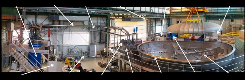
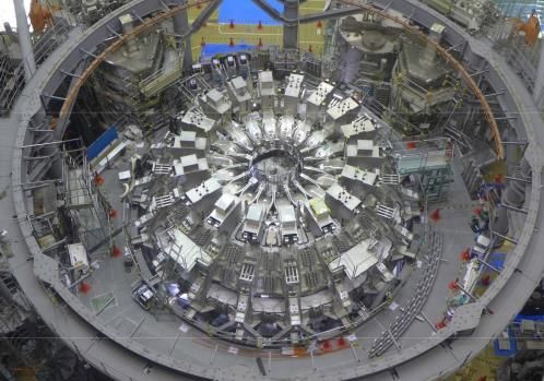
JT-60SA TF COILS FULLY ASSEMBLED
 ANNEX 3
 SINCE 18/06/2018

Commissariat à l’énergie atomique et aux énergies alternatives
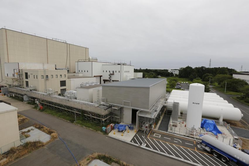
ANNEX 4 JT-60SA CRYOGENIC SYSTEM (CEA/F4E)

 Cryogenic
 Hall Compressor six He gas
 Building storage vessels

 LN2
 tank
Commissariat à l’énergie atomique et aux énergies alternatives
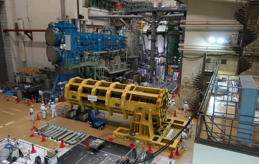
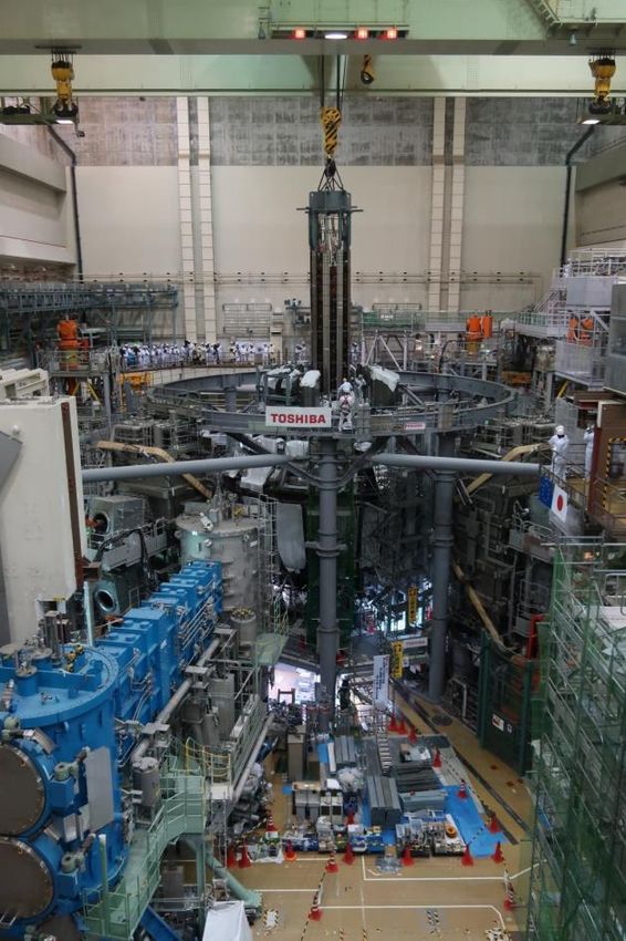
ANNEX 5 JT-60SA CS DELIVERED TO NAKA 16/03/2019

Commissariat à l’énergie atomique et aux énergies alternatives
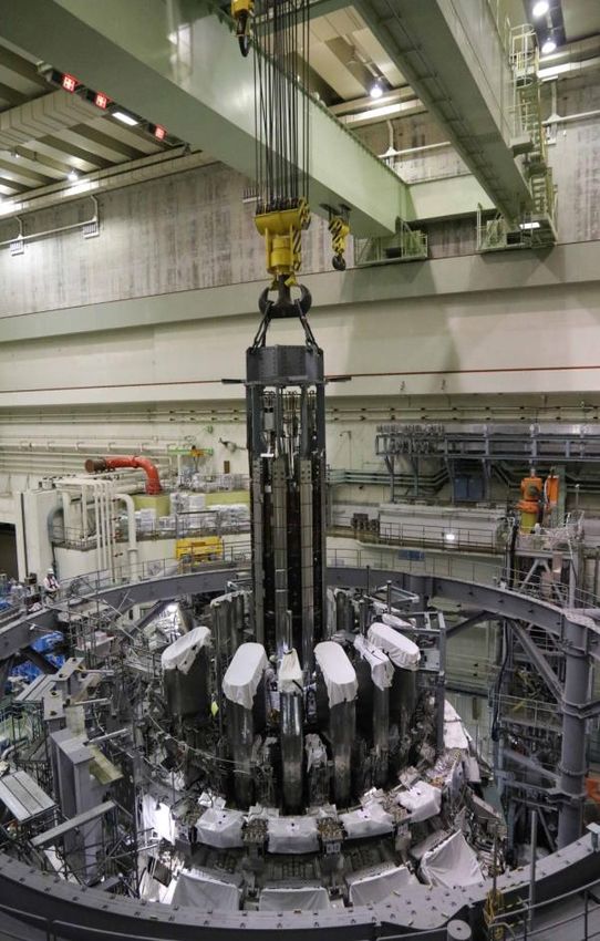
ANNEX 6 JT-60SA CS INSERTED

Commissariat à l’énergie atomique et aux énergies alternatives
You can also read