Landing Site Selection - ExoMars 2018 User's Manual - ESA
←
→
Page content transcription
If your browser does not render page correctly, please read the page content below
ExoMars 2018

Landing Site Selection
      User’s Manual

       Ref: EXM-SCI-LSS-ESA/IKI-003
       Version 1.0, 17 December 2013

                                       1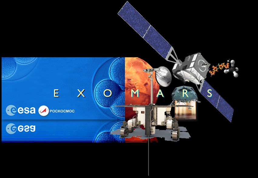
Table of Contents

1
   INTRODUCTION AND SCOPE ............................................................................................................................ 3

   1.1
   ExoMars 2018 Mission Summary ................................................................................................................... 4


2
   SCIENTIFIC CONSTRAINTS FOR EXOMARS 2018 LANDING SITES .............................................................. 5

   2.1
   Rover Surface Mission ................................................................................................................................... 5

   2.2
   Surface Platform Surface Mission .................................................................................................................. 6

   2.3
   Landing Site Scientific Constraints ................................................................................................................. 6

     2.3.1
   Depositional Age of Terrain ..................................................................................................................... 6

     2.3.2
   Preservation of Organics ......................................................................................................................... 6

     2.3.3
   Signatures of Past Aqueous Activity ........................................................................................................ 6

     2.3.4
   Availability and Distribution of Outcrops .................................................................................................. 6

     2.3.5
   Paucity of Dust Coverage ........................................................................................................................ 7


3
   ENGINEERING CONSTRAINTS AND PERFORMANCE DRIVERS FOR EXOMARS 2018 LANDING SITES . 8

   3.1
   EDL Engineering Constraints and Performance Drivers ................................................................................ 8

     3.1.1
   Landing Elevation .................................................................................................................................... 8

     3.1.2
   Local Time and Season ........................................................................................................................... 8

     3.1.3
   Landing Ellipse Size and Orientation ....................................................................................................... 8

     3.1.4
   Terrain Relief and Slopes ........................................................................................................................ 9

     3.1.5
   Rock Distribution .................................................................................................................................... 10

     3.1.6
   Radar Reflectivity ................................................................................................................................... 10

     3.1.7
   Atmospheric Parameters ....................................................................................................................... 11

   3.2
   Rover Engineering Constraints and Design Capability ................................................................................. 11

     3.2.1
   Mobility System Description ................................................................................................................... 11

     3.2.2
   Latitude .................................................................................................................................................. 12

     3.2.3
   Surface Thermophysical Properties ....................................................................................................... 12

     3.2.4
   Traverse Range and Rover velocity ....................................................................................................... 12

     3.2.5
   Static Stability and Slope Access ........................................................................................................... 13

     3.2.6
   Surface Winds ........................................................................................................................................ 14

   3.3
   Preliminary Summary Tables for Engineering Constraints ........................................................................... 15


4
   PLANETARY PROTECTION CONSTRAINTS FOR EXOMARS 2018 LANDING SITES ................................. 17

   4.1
   No Access to “Mars Special Regions” .......................................................................................................... 17


5
   LIST OF ACRONYMS AND ABBREVIATIONS ................................................................................................. 18


                                                                                                                                                                              2
1 INTRODUCTION AND SCOPE
Establishing whether life ever existed, or is still active on Mars today, is one of the outstanding scientific questions
of our time. The ExoMars Programme seeks to timely address this and other important scientific goals, and to
demonstrate key flight and in situ enabling technologies underpinning European and Russian ambitions for future
exploration missions. The ExoMars Programme is a cooperative undertaking between the European Space Agen-
cy (ESA) and the Russian federal space agency, Roscosmos.
Within ESA, ExoMars is an element of the Aurora Exploration Programme, an optional programme executed under
the supervision of the Programme Board for Human Spaceflight, Microgravity and Exploration (PB-HME). In addi-
tion, the ESA Science Programme also participates to ExoMars. The objective of the Aurora Programme is to ex-
plore Solar System objects having a high potential for the emergence of life. Aurora aims to develop technologies
and address scientific questions in a step-wise fashion, seeking to advance the level of technical and scientific
readiness with each successive mission.
Within Roscosmos, ExoMars is part of the Russian federal space programme and is supported by the Russian
Academy of Sciences.
To prepare for future exploration missions and to support the Programme’s scientific objectives, ExoMars will
achieve the following technology objectives:
Entry, Descent, and Landing (EDL) of a payload on the surface of Mars;
Surface mobility with a Rover;
Access to the subsurface to acquire samples;
Sample acquisition, preparation, distribution, and analysis.
Qualification of Russian ground-based means for deep-space communications in cooperation with
ESA’s ESTRACK;
Adaptation of Russian on-board computer for deep space missions and ExoMars landed operations;
Development and qualification of throttleable braking engines for prospective planetary landing mis-
sions.
The scientific objectives of ExoMars are:
To search for signs of past and present life on Mars;
To investigate the water/geochemical environment as a function of depth in the shallow subsurface;
To study martian atmospheric trace gases and their sources.
To characterise the surface environment.
1
The ExoMars Programme consists of two missions, in 2016 and 2018. ESA and Roscosmos have agreed a well-
balanced sharing of responsibilities for the various mission elements.
The 2016 mission will be launched on a Roscosmos-provided Proton rocket. It includes the Trace Gas Orbiter
(TGO) and an Entry, descent and landing Demonstrator Module (EDM), both contributed by ESA. The TGO will
carry European and Russian scientific instruments for remote observations, while the EDM will have a European
payload for in-situ measurements during descent and on the martian surface.
The 2018 mission will land a Rover, provided by ESA, making use of a Descent Module (DM) contributed by Ros-
cosmos. The DM will travel to Mars on an ESA-provided Carrier Module (CM). Roscosmos will launch the space-
craft composite on a Proton rocket. The Rover will be equipped with a European and Russian suite of instruments,
and with Russian Radioisotope Heating Units (RHUs). The Rover will also include a 2-m drill for subsurface sam-
pling and a Sample Preparation and Distribution System (SPDS), supporting the suite of geology and life seeking
experiments in the Rover’s Analytical Laboratory Drawer (ALD). The Russian Surface Platform (SP) will contain a
further suite of instruments, mainly concentrating on environmental and geophysical investigations.
1
Agreement between the European Space Agency and the Federal Space Agency (the Russian Federation) concerning coop-
eration on robotic exploration of Mars and other bodies in the Solar System, signed on 14 March 2013 [Ref. ESA/C(2013)19].
3NASA will also deliver important elements to ExoMars: The Electra Ultra-High Frequency (UHF) radio package on
TGO for Mars surface proximity link communications with landed assets (such as the Rover and Surface Platform);
engineering support to EDM; and a major part of MOMA, the organic molecule characterisation instrument on the
Rover.
This Landing Site Selection (LSS) User’s Manual lists the scientific, engineering, and planetary protection con-
straints against which the ExoMars 2018 Landing Site Selection Working Group (LSSWG) will analyse proposed
candidate landing sites. Please note that the landing constraints included in this document may need to be revised
in case of changes in the spacecraft’s expected landing performance.
1.1 ExoMars 2018 Mission Summary
Table 1 presents the 2018 mission’s principal features.
Spacecraft: Carrier Module (CM) plus 2000-kg Descent Module (DM), including
Rover and Surface Platform (SP).
Data relay function to be provided by ExoMars TGO.
Launch: May 2018, from Baikonur on a Proton M (backup in Aug 2020).
Arrival: Jan 2019 (backup in Apr 2021).
Landing: Direct entry, from hyperbolic trajectory, after the dust storm season.
Landing site: To be defined.
Must be safe and appropriate for “search for life” science.
Latitudes between 5º S and 25º N, all longitudes.
Maximum altitude: –2 km, relative to MOLA zero level.
Uncertainty ellipse: ~104 km x 19 km.
Science: Rover with Pasteur payload:
Mass ~310 kg, including drill/SPDS and instruments.
Lifetime 218 sols.
Surface Platform:
SP Instruments to be defined.
Lifetime 1 martian year
Ground Segment: Mission operations centre: ESOC.
Rover Operations Control Centre: ALTEC.
Surface Platform operations: IKI.
Mission science archives: ESAC and IKI.
Table 1: ExoMars 2018 mission information.
42 SCIENTIFIC CONSTRAINTS FOR EXOMARS 2018 LANDING SITES
The ExoMars programme’s scientific objectives are:
1. To search for signs of past and present life on Mars;
2. To investigate the water/geochemical environment as a function of depth in the shallow subsurface;
3. To study martian atmospheric trace gases and their sources;
4. To characterise the surface environment.
The ExoMars Rover will address the first two science objectives. It will carry a comprehensive suite of instruments
dedicated to geology and exobiology research named after Louis Pasteur. The rover will be able to travel several
kilometres searching for traces of past and present signs of life. It will do this by collecting and analysing samples
from within outcrops, and from the subsurface—down to 2-m depth. The very powerful combination of mobility with
the ability to access locations where organic molecules can be well preserved is unique to this mission. The rover
will also perform numerous investigations on rocks and soils, also contributing to the fourth objective.
After the rover will have egressed, the ExoMars Surface Platform (SP) will begin its science mission. The SP will
conduct environmental and geophysical measurements in support of the fourth objective. These results will also
provide important context information for objective 1, benefiting also the Rover mission.
Besides the investigations carried out by each element, the programme also includes an excellent potential for
cross-platform scientific studies. For example, coordinated measurements between the Rover and TGO may pro-
vide insights into the past and present habitability of Mars. Likewise, the Surface Platform and Rover will be able to
image each other, and implement joint scientific measurements during the first part of their surface mission, while
they are close together.
From a science point of view, a landing site satisfying the Rover mission’s search-for-life requirements is also ex-
pected to be extremely interesting for the Surface Platform’s science.
2.1 Rover Surface Mission
The ExoMars rover will have a nominal lifetime of 218 sols (approximately 7 months). During this period, it will en-
sure a regional mobility of several kilometres, relying on solar array electrical power.
The rover’s Pasteur payload will produce self-consistent sets of measurements capable to provide reliable evi-
dence, for or against, the existence of a range of biosignatures at each search location. Pasteur contains: pano-
ramic instruments (wide-angle and high-resolution cameras, an infrared spectrometer, a ground-penetrating radar,
and a neutron detector); a subsurface drill capable of reaching a depth of 2 m to collect specimens; contact instru-
ments for studying rocks and collected samples (a close-up imager and an infrared spectrometer in the drill head);
a Sample Preparation and Distribution System (SPDS); and the analytical laboratory, the latter including a visual
and infrared imaging spectrometer, a Raman spectrometer, and a Laser-Desorption, Thermal-Volatilisation, Deri-
vatisation, Gas Chromatograph Mass Spectrometer (LD + Der-TV GCMS).
If any organic compounds are detected on Mars, it will be important to show that they were not brought from Earth.
Great care is being devoted during the assembly, testing, and integration of instruments and rover components.
Strict organic cleanliness requirements apply to all parts that come into contact with the sample and to the rover
assembly process. Once assembled, the analytical laboratory drawer will be sealed and kept at positive pressure,
throughout transport, final integration, launch, cruise, and landing on Mars. The ExoMars rover will also carry a
number of blank calibration samples to reliably demonstrate that it is free from contaminants. Upon landing, one of
the first science actions will be for the drill to pass a blank sample to the analytical laboratory.
52.2 Surface Platform Surface Mission
The ExoMars Descent Module (DM) is the part of the spacecraft composite that enters the atmosphere to achieve
a controlled descent and landing. The Carrier Module (CM) will take the DM to Mars and deliver it with a very pre-
cise entry angle. The DM will hit the top of the martian atmosphere at approximately 20,000 km/h. A thermal
shield at the bottom of the capsule will be used to decelerate to roughly twice the speed of sound. Thereafter, the
parachute system will take over. However, even after the main parachute has reached its terminal velocity, the DM
will be still traveling at more than 300 km/h. The last stage will involve the use of throttled liquid engines. A multi-
beam radar will measure the distance to ground and the horizontal speed over the terrain. The DM’s computer will
receive this information and combine it with its knowledge of the DM’s attitude to decide how to exercise the en-
gines and achieve a controlled landing. Legs will be used for the final touchdown.
The Rover, which sits on top of the Surface Platform (SP), will then unfold its solar panels, camera mast, and
wheels. The SP will deploy ramps that the rover can use to move onto the martian surface. Most likely, a few days
will be required to image the surroundings and decide which is the safest exit direction for the rover to leave the
lander. Once the Rover has egressed, the SP will conduct environment and geophysics experiments for about a
martian year, relying on solar array electrical power. The SP payload has not been selected yet.
2.3 Landing Site Scientific Constraints
For the ExoMars Rover to achieve results regarding the possible existence of biosignatures, the mission has to
land in a scientifically appropriate setting.
2.3.1 Depositional Age of Terrain
The site must be ancient (older than 3.6 Ga)—from Mars’ early, habitable period: Pre- to late-Noachian (Phyl-
losian), possibly extending into the Hesperian.
2.3.2 Preservation of Organics
Regarding the search for molecular biosignatures, the LSSWG would consider favourably sites providing easy ac-
cess to locations with reduced radiation accumulation in the subsurface. The presence of fine-grained sediments
(on Earth, organic molecules are better preserved in fine-grained sediments—which are more resistant to the pene-
tration of biologically-damaging agents, such as oxidants—than in coarse materials) in units of recent exposure age
would be very desirable. Young craters can provide the means to access deeper sediments, and studies on Earth
suggest that fossil biomarkers can survive moderate impact heating. Additionally, impact related hydrothermal
fractures may have contributed to creating habitats for microbial life in the past. However, for landing safety rea-
sons it is better not to have many craters in the ellipse, so sites exposed by high erosion rates would appear pref-
erable.
2.3.3 Signatures of Past Aqueous Activity
The site must show abundant morphological and mineralogical evidence for long duration, or frequently reoccur-
ring, aqueous activity.
2.3.4 Availability and Distribution of Outcrops
The site must include numerous sedimentary rock outcrops. The outcrops must be distributed over the landing
ellipse to ensure that the rover can get to some of them (the expected rover traverse range is a few km—during the
mission’s 218-sol nominal duration).
As an indication, assuming the mission lands in a scientifically interesting area, the Reference Surface Mission
(RSM) scenario for the rover’s 218-nominal mission duration results in roughly three quarters of the time spent per-
forming science, and one quarter traversing to new science locations—each assumed to be on the order of 500 m
6apart. The rover would be able to increase its traveling range, e.g. if deemed useful to reach a particularly interest-
ing location, but this would be at the expense of science time.
2.3.5 Paucity of Dust Coverage
It is essential to avoid loose dust deposits distributed by aeolian transport. The site must have little dust coverage.
Scientifically there are two reasons for this: 1) Dust is not an interesting target for the rover. While driven by the
wind, this material has been processed by UV radiation, ionising radiation, and potential oxidants in the atmos-
phere and on the surface of Mars. Any organic biomarkers would be highly degraded, or even completely de-
stroyed, in these samples. 2) The usefulness of the drill will be nullified if the landing site has a dust layer thicker
than the drill’s maximum penetration depth.
73 ENGINEERING CONSTRAINTS AND PERFORMANCE DRIVERS FOR
EXOMARS 2018 LANDING SITES
Engineering constraints are criteria that, in case they are not satisfied, can result in a candidate landing site being
judged unfeasible for the mission and therefore rejected.
This section addresses landing site characteristics relevant for:
Safe entry descent and landing;
Safe surface operations;
Maximization of rover performance.
3.1 EDL Engineering Constraints and Performance Drivers
The ExoMars 2018 Descent Module (DM) is in its design phase. Therefore all values reported herein are subject of
continuous updates as the project work evolves.
3.1.1 Landing Elevation
The landing site’s elevation must allow an adequate atmospheric column capable of providing the drag and time
needed for the successful completion of all Entry, Descent, and Landing (EDL) events.
The maximum altitude achievable by the landing system is –2 km with respect to the MOLA geoid. Therefore, the
terrain elevation within the landing ellipse pattern must be ≤ –2 km MOLA.
3.1.2 Local Time and Season
For a nominal launch in the 2018 launch opportunity, the ExoMars mission will land in Ls = 324º at a Local Solar
True Time between 10:00 and 11:05 (morning).
For a backup launch in the 2020 launch opportunity, the ExoMars mission will land in Ls = 34º at a Local Solar True
Time between 10:55 and 12:40 (late morning).
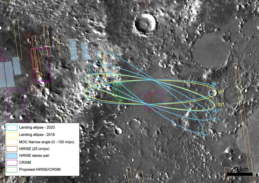
3.1.3 Landing Ellipse Size and Orientation
With robust margin to account for off-track radar operations (i.e. while oscillating under the parachute), the landing
ellipse under evaluation for site selection is 104 km x 19 km.
The orientation of the landing ellipse will change depending on when the launch takes place within a given launch
window. As shown in Fig 1, for the 2018 launch opportunity (in yellow), the orientation of the landing ellipse can
vary between 90° and 102° azimuth (computed clockwise from the North direction). For a 2020 launch (in light-
blue), the landing ellipse azimuth can span the 88°–127° range. This effectively defines a landing ellipse pattern,
achieved by rotating the 104 km x 19 km (3 sigma) landing ellipse between 88° and 127°.
Since it is required that landing sites be complaint with both launch opportunities, the adequacy of candidate land-
ing sites against the applicable scientific, engineering, and planetary protection constraints will be verified over the
entire landing ellipse pattern.
8Landing ellipse - 2020 (104 km x 19 km)
Landing ellipse - 2018 (104 km x 19 km)
MOC Narrow angle (0 – 100 m/px)
HiRISE (25 cm/px)
HiRISE Stereo pair
CRISM
Proposed HiRISE/CRISM
Fig. 1: Example of an ExoMars (104 km x 19 km) landing ellipse pattern. For a 2018 launch (in yellow), the orien-
tation of the landing ellipse can vary between 90° and 102° azimuth (computed clockwise from the North direction).
For a 2020 launch (in light-blue), the landing ellipse azimuth can span the 88°–127° range, depending on the
launch date within the 2020 launch window opportunity. The ellipse pattern is centred at 18.36° N, 77.59° E, at an
elevation of –2.66 km with respect to the MOLA geoid in planetocentric coordinates. The footprints of existing
HiRISE, CRISM (in purple), and MOC (orange) images are shown. In green are depicted new, requests for a
HiRISE image (rectangle) and a CRISM image (hourglass shape) centred at 18.365° N, 77.719° E.
3.1.4 Terrain Relief and Slopes
Terrain relief features and slopes constitute EDL performance drivers, as they may impact radar measurements
and affect the stability of the landing platform.
The radar Doppler altimeter velocimeter uses multiple beams to measure the vertical and horizontal components of
the descent velocity vector. The initial measurements are acquired after jettisoning the DM’s front shield, while the
vehicle is still hanging under its parachute. Continuous measurements are performed throughout the descent
phase, until 10 m above the local ground level; thereafter the radar is switched off.
Over the whole descent trajectory, slopes at various length scales can alter the knowledge of “distance to ground at
landing”, with potential serious consequences on fuel consumption, control authority, and landing conditions.
9At present, the slope constraint set points are defined to be:
Base-length Slope Requirement Rationale
2000 m ≤ 3° To ensure slant and incidence compatible with radar.
330 m ≤ 8.6°° To ensure proper fuel consumption during powered descent.
7m ≤ 12.5°° To ensure an adequate altitude error at touchdown.
2m ≤ 15°° (TBC) To ensure stability at landing.
The analysis of landing sites will be performed based on the following assumptions:
Length scales of 2 to 10 km: Slope ≤ 3° on base-length of 2000 m.
Rationale: This requirement is driven by the specification of maximum
slant range to be measured. The radar may be activated in the alti-
tude range 3.0–6.5 km, but not operated in closed-loop until an alti-
tude of 2500 m has been reached. Unambiguous altitude measure-
ment is necessary for altitudes below 2500 m. The radar does not
operate in closed-loop on base lengths ≥ 2 km. The radar is active on
base lengths ≤ 5 km.
Length scales of 0.33 to 2 km: Exponential self-affine model C⋅ΔX(H-1),
leading from 3° at 2000 m to 8.6° at 330 m.
Length scales of 7 to 330 m: Exponential self-affine model C⋅ΔX(H-1),
leading from 8.6° at 330 m to 12.5° at 7 m.
Rationale: Ensure proper control authority and fuel consumption dur-
ing powered descent.
Length scales up to 7 m: Maximum relief 1.55 m up to a maximum slope of 18°. Corresponds
to 12.5° on a 7-m base length, and 17.2° over a 5-m base length.
Rationale: To minimise the altitude error at landing.
3.1.5 Rock Distribution
The landing platform is designed with a clearance between nozzles and terrain of 0.35 m as the legs touch down,
and 0.18 m following deformation of the legs’ shock absorbers. Currently, the required clearance for the landing
platform is 0.18 m (TBC).
Until this parameter has been confirmed, the applicable EDL rock distribution constraint is that the site must have a
rock abundance ≤ 7%— derived from the rover constraint for rock abundance.
3.1.6 Radar Reflectivity
The ExoMars 2018 EDL design requires that the surface materials present at the landing site be radar reflective,
providing sufficient backscatter signal to enable measuring the altitude and velocity with respect to ground during
the descent. The relevant constraints have been determined on the basis of a realistic assessment of terrain re-
flectivity.
The following ranges for backscattering constraints are driven by the current radar requirements.
Terrain Backscattering at nadir: –15 dB to 27.5 dB
Terrain Backscattering at 10° off-nadir: –17 dB to –10 dB
Terrain Backscattering at 20° off-nadir: –18 dB to –13 dB
Maximum Backscattering decay from 0° to 5° off-nadir: –30.4 dB
Maximum Backscattering decay from 0° to 10° off-nadir: –37.3 dB
Maximum Backscattering decay from 0° to 15° off-nadir: –40.6 dB
103.1.7 Atmospheric Parameters
The ExoMars 2018 DM is being designed to land safely and accurately under a range of atmospheric conditions.
In order to ensure the expected performance can be achieved, “not to exceed” thresholds have been defined for
atmospheric density, horizontal, and vertical winds.
The applicability of these thresholds is altitude dependent since they are associated with sensitive events in the
EDL sequence, such as peak deceleration, deployment of parachutes, terminal descent velocity, initiation of pow-
ered descent, etc.
From entry through the descent phase (parachutes), altitude references for atmospheric parameters are given with
respect to the local MOLA geoid. However, following front shield ejection—when the radar will start operating—
altitude references are given with respect to ground. The set of atmospheric thresholds used for the DM design is
listed in the summary table provide at the end of this chapter.
3.2 Rover Engineering Constraints and Design Capability
This chapter describes the rover design capabilities to allow assessing the feasibility of reaching scientific points of
interest within the landing ellipse pattern.
As the rover system is still under development, the characteristics reported herein are indicative and remain to be
confirmed and tested to the necessary extent.
The rover’s effective capabilities depend on the type of the terrain, on the power/energy availability, and on the en-
vironment. The season, the latitude, the nature and inclination of the terrain, the near surface wind, the atmospher-
ic dust opacity, the dust deposition rate are all factors that can affect rover performance. For the sake of clarity,
this will not be recalled systematically in the following sections.
The rover will be commanded from Earth by means of Activity Plans. These Activity Plans will be prepared and
checked to ensure their compatibility with available rover resources at the time of their planned execution. The
rover will include on-board intelligence, allowing it to autonomously:
Stop the execution of an Activity Plan in case of trouble or lack of resources (e.g. the environmental condi-
tions may have changed with respect to the ground prediction) and reach a safe state;
Replan the Sol’s activities based on alternatives previously defined by Ground Control;
Travel safely to a target designated by Ground Control, avoiding hazards such as rocks, steep slopes, and
crevasses.
3.2.1 Mobility System Description
The ExoMars rover has six driving wheels capable of steering. Deployment actuators are available to raise the
rover on the Surface Platform, before egress. The rover size is approximately 1.7 m in length by 1.5 m in width
(excluding the solar arrays).
The wheels are mounted on three bogies (one on each side, and one on the rear) that can rotate relative to the
body to provide passive adaptation to the terrain shape and keep the wheels on the ground. The wheels are flexi-
ble to increase their contact surface. The wheels’ diameter is 285 mm and their width is 120 mm, resulting in an
2
approximate indicative surface load under each wheel of 14.6 kN/m . The landing site terrain must be able to bear
such load; therefore, very thick layers of loose soil must be avoided.
The rover is designed to drive over 25 cm step obstacles and over crevasses of 15 cm width.
The rover’s nominal ground clearance is about 30 cm.
11The rover can be controlled from Earth with various levels of commanding to:
Execute low-level manoeuvre commands, such as Ackerman curves, point turns, or crabbing—thanks to its
six-steering-wheels capabilities;
Execute a trajectory using vision-based position control;
Perform on-board path planning (based on autonomous hazard detection using stereo cameras at about 2 m
above the ground mounted on a pan-tilt assembly) and execute a trajectory using vision-based position con-
trol.
Energy considerations, terrain slopes, rock distribution, and soil characteristics can affect rover trafficability. For
design and test purposes, a number of reference terrains have been defined (not reported herein).
3.2.2 Latitude
The ExoMars rover is designed to operate in the latitude range between 5°° S to 25°° N.
3.2.3 Surface Thermophysical Properties
The ExoMars rover is designed for:
-2 -0.5 -1
Surfaces having thermal inertia ≥ 150 J m s K .
Surfaces having 0.1 ≤ albedo ≤ 0.26.
3.2.4 Traverse Range and Rover velocity
The ExoMars Rover is designed to traverse 4 km along track, consistent with the requested capability of being able
to drive 500 m between each of six experiment sites within its 218-sol nominal mission duration.
The rover’s nominal commanded speed is about 40 m/h. However, wheel slippage can increase depending on the
terrain (soil type, slope, rocks); the effective speed would then be smaller. For activities requiring very accurate
positioning, the rover’s speed can be reduced to about 10 m/h. On very easy terrains, the maximum 70 m/h speed
could be achieved—mainly on a straight line on flat ground.
By using its on-board path planning capability every few meters, the rover can compute autonomously a path to-
ward any Earth-specified goal coordinates. This functionality, however, reduces the rover’s average speed to
about 15 m/h, allowing to drive approximately 70 m/sol—along the path on a terrain with overall rock abundance of
6.9% [M. Golombek and D. Rapp (1997) “Size-frequency distributions of rocks on Mars and Earth analog sites: Im-
plications for future landed missions” Journal of Geophysical Research 102, 4117-4129].
Assuming the following additional terrain characteristics for soil and slope distributions, representative point-to-
point travel distances per sol can be estimated. Table 2 presents simulation results for a “crusty/cloddy/silty sand”
type of soil.
12Ls/Lat. 5°S
0°N
15°N
25°N
324° 72 68 63 41
340° 69 72 65 47
0° 64 71 69 55
30° 55 66 72 62
60° 44 61 72 66
71° 41 59 73 67
Table 2: ExoMars rover Autonomous Navigation representative travel distances (point-to-point, in metres) per sol
3
as a function of Ls and latitude for soil of type “crusty/cloddy/silty sand” with bulk density of 1800 kg/m . The adi-
rectional slope distribution on a 5-m scale follows a Chi-Square distribution with parameter 7 and a maximum slope
of 21.5°. The on-board path planning standard settings would avoid slopes ≥ 20° and hemispheric rocks of 20 cm
height.
For much easier terrains trajectories can be planned on Earth, uploaded, and executed by the rover. The achieva-
ble point-to-point distance per sol would obviously depend on the terrain, but also on the ability of Ground Control
to accurately assess the terrain difficulties up to the desired target. With good conditions, 150 m/sol point-to-point
could be reasonably executed, although it must be noted that this remains to be tested.
Finally, for terrains presenting intermediate difficulties, Ground Control could specify the initial part of the traverse,
based on available images/data, and the rest of the trajectory could be executed using on-board path planning.
Simulation results for one such example are presented in Table 3.
Ls/Lat. 5°S
0°N
15°N
25°N
324° 98 95 89 68
340° 95 99 92 74
0° 91 97 95 82
30° 82 93 98 89
60° 71 87 99 93
71° 68 85 99 94
Table 3: ExoMars rover combined Trajectory Execution plus Autonomous Navigation indicative travel distances
(point-to-point, in metres) per sol as a function of Ls and latitude on terrain as above. In this case the first 40 m are
assumed planned by Ground Control (i.e. not autonomous navigation).
3.2.5 Static Stability and Slope Access
The rover has been designed to be statically stable on slopes ≤ 40° with respect to the horizontal plane. Some
margin will be included during operations to ensure safety at all times. Additionally, on-board monitoring of the
rover tilt will prevent any dangerous situations.
The rover’s drill and analytical laboratory are designed to work with a rover body inclination ≤ 10°
with
respect
to
the
horizontal
plane.
13The rover mobility system will allow driving on terrains with slopes. The rover will experience slippage that will limit
the maximum slope inclination depending on the soil type. Allowable slopes are given below for various types of
terrain.
Slope ≤ 26° for gravel and medium to coarse sand;
Slope ≤ 21° for very fine sand;
Slope ≤ 10° for fine dust.
The rover will be able to extricate itself from a situation where two front wheels are buried up to the middle. These
known dangerous situations will be avoided as much as possible by continuous slippage monitoring.
3.2.6 Surface Winds
Horizontal Wind: ≤ 30 m/s at 1 m above ground level (during rover surface operations).
Vertical Wind: ≤ 12 m/s at 1 m above ground level (during rover surface operations).
143.3 Preliminary Summary Tables for Engineering Constraints
Since the ExoMars 2018 mission is under development, these constraints are preliminary. The final constraints will
be confirmed in the course of the project’s life cycle.
Engineering Parameter Requirement Notes
Driven by Surface Platform and Rover design.
Latitudes beyond this range would cause either de-
graded electrical power, or challenging thermal con-
Landing Latitude 5º S to 25º N
ditions.
Latitudes within the 0°–15° N band maximise the
rover’s travelling capabilities.
Landing Elevation ≤ –2 km MOLA For sufficient atmospheric braking during EDL.
Major axis: 104 km Landing ellipse dimensions where all listed con-
Landing Ellipse Dimensions
Minor Axis: 19 km straints must be verified.
Azimuth angles measured clockwise from north.
88° to 127º Ellipse Orientation will vary slightly depending on the
Landing ellipse Orientation
landing site’s latitude.
Slopes at 2- to 10-km
≤ 3.0° To ensure slant and incidence compatible with radar.
length scale
Slopes at 330-m length To ensure proper fuel consumption during powered
≤ 8.6°°
scale descent.
To ensure proper altitude error in the touchdown
Slopes at 7-m length scale ≤12.5°°
phase.
Slopes at 2-m length scale ≤15.0°° To ensure stability at landing
Drives the rover traverse performance and also
Rock abundance K –15 dB and < 27.5 dB are described in the dedicated section.
Table 4: Summary of preliminary surface/terrain engineering constraints.
15Sound
Altitude Density Horizontal Winds Vertical Winds Event Driver
Speed
≤ 15 % (TBC)
40 km MOLA Deceleration
uncertainty
≤ 8 %(TBC) ≤ 5 % (TBC) Drogue parachute
6–10 km MOLA Max ≤ 25 m/s (TBC) Max ≤ 12 m/s (TBC)
uncertainty uncertainty deployment
≤ 5 % (TBC) Main parachute de-
4–6 km MOLA Max ≤ 25 m/s (TBC) Max ≤ 12 m/s (TBC)
uncertainty ployment
Main parachute de-
1–4 km MOLA Max ≤ 25 m/s (TBC) Max ≤ 12 m/s (TBC) –
scent
Parachute terminal
10–600 m 3
> 13 g/m Max ≤ 25 m/s (TBC) Max ≤ 12 m/s (TBC) – velocity and powered
above ground
descent
0–10 m above Final descent and
Max ≤ 25 m/s Max ≤ 12 m/s (TBC) –
ground touchdown
1 m above Rover surface opera-
Max ≤ 30 m/s Max ≤ 12 m/s –
ground tions
Table 5: Summary of preliminary atmospheric engineering thresholds. The thresholds for altitudes above 6 km
must not be exceeded anywhere along the portion of the descent trajectory that lies within 100 km of the proposed
landing site. All thresholds for uncertainty are specified as 3-sigma (99.87 % probability) values. The thresholds
for maximum horizontal and vertical wind speed apply to all landing sites, regardless of their elevation.
164 PLANETARY PROTECTION CONSTRAINTS FOR EXOMARS 2018
LANDING SITES
4.1 No Access to “Mars Special Regions”
The ExoMars 2018 mission is not compatible with landing in a Mars Special Region. A Mars Special Region is de-
fined as any area providing an environment (even if for just a few hours a year) where both the following threshold
levels are exceeded: temperature (> –25°C) and water activity (> 0.5). A proposed landing site must not contain
features currently considered as Mars Special Regions: gullies, bright streaks associated with gullies, and pasted-
on terrain. Any evidence of dark streaks or recurrent slope lineae (RSL) in a proposed landing site must be identi-
fied (please indicate if the resolution of the available data is insufficient to perform this task). The determination of
whether any such features would constitute a Mars Special Region would be the subject of a case-by-case evalua-
tion.
175 LIST OF ACRONYMS AND ABBREVIATIONS
AO Announcement of Opportunity.
ALD Analytical Laboratory Drawer.
CM Carrier Module. The spacecraft element transporting the DM to Mars.
DM Descent Module. The part of the spacecraft composite that enters the atmosphere for landing—
typically a capsule.
EDL Entry, Descent, and Landing.
ESA European Space Agency.
ESAC European Space Astronomy Centre, in Madrid (ES).
ESOC European Space Operations Centre, in Darmstadt (DE).
ESTEC European Space Technology and Research Centre: ESA’s largest establishment, located in Noord-
wijk (NL).
ESWT ExoMars Science Working Team: The group of scientists that advises ESA on all aspects of the Pro-
gramme affecting its scientific performance.
GCMS Gas Chromatograph / Mass Spectrometer: Two analytical instruments that, combined, are very useful
to analyse complex gas mixtures. They can provide elemental, molecular, and isotopic abundances
and composition.
HESAC Human Spaceflight and Exploration Science Advisory Committee. Since 2010 HESAC is the senior
advisory committee on matters regarding ESA’s Aurora Exploration Programme.
IKI Russian Academy of Sciences organism conducting space research.
IR Infrared.
LSS Landing Site Selection.
LSSWG Landing Site Selection Working Group.
20
Mb Mega-bit: a unit of data volume equal to 2 bits of information.
MER Mars Exploration Rovers: A NASA programme that landed two very successful rovers in 2004, devot-
ed mainly to surface geochemistry and mineralogy research.
MOLA Mars Orbiter Laser Altimeter: An instrument for measuring relief height in NASA’s Mars Global Sur-
veyor (MGS). The 0-MOLA ellipse has become the de facto reference for measuring altitude on Mars.
MSL Mars Science laboratory: A NASA programme that landed the Curiosity rover on Gale crater in 2012.
NASA National Aeronautics and Space Administration—the space agency of the United States of America.
Pyr Pyrolysis is a technique to render organic compounds volatile by subjecting them to high tempera-
tures. It is usually employed as a first stage in combination with a GCMS, resulting in a Pyr-GC-MS
instrument. This method is sometimes also called Thermal Volatilisation (TV), and can be performed
18with or without involving derivatisation agents—chemical compounds that attach to small molecules to
help render them volatile.
ROCC Rover Operations Control Centre, to be located at ALTEC, in Turin (ITA).
SOC Science Operations Centre.
SP Surface Platform. The science element, part of the lander, that becomes active after Rover egress.
SPDS Sample Preparation and Distribution System.
TGO Trace Gas Orbiter.
UV Ultraviolet, usually used for ultraviolet radiation or ultraviolet light.
19You can also read


