Large-field high-resolution mosaic movies - SPIE Digital Library
←
→
Page content transcription
If your browser does not render page correctly, please read the page content below
Large-field high-resolution mosaic
                 movies

                 Robert H. Hammerschlag
                 Guus Sliepen
                 Felix C. M. Bettonvil
                 Aswin P. L. Jägers
                 Peter Sütterlin
                 Yong Lin
                 Sara F. Martin
                 Olga Panasenco
                 Eugene P. Romashets

Downloaded From: https://www.spiedigitallibrary.org/journals/Optical-Engineering on 09 Aug 2021
Terms of Use: https://www.spiedigitallibrary.org/terms-of-use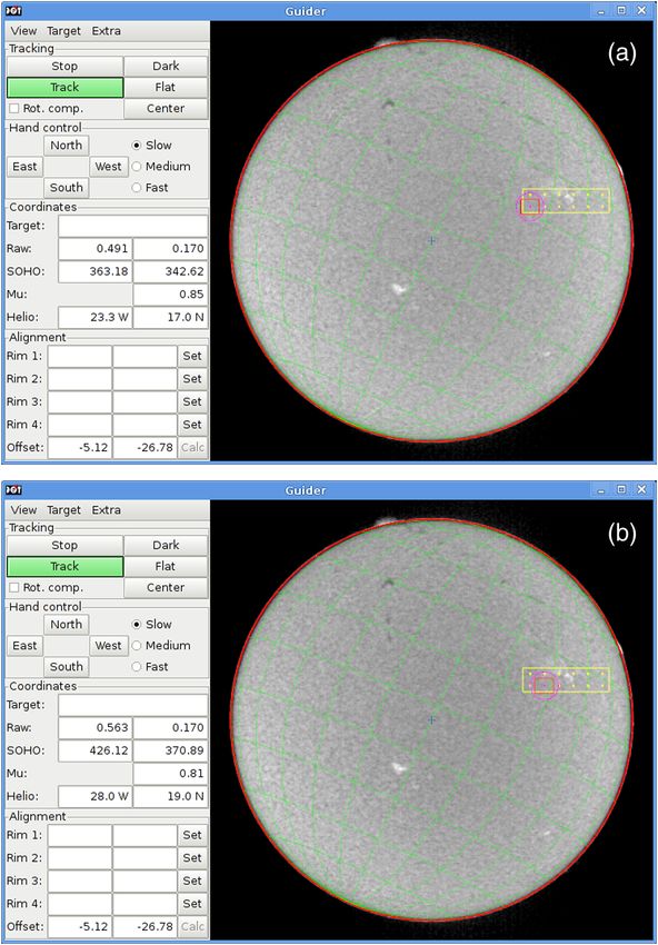
Optical Engineering 52(8), 081603 (August 2013)

                Large-field high-resolution mosaic movies
                Robert H. Hammerschlag                                              Abstract. Movies with fields-of-view larger than normal, for high-resolu-
                Leiden Observatory                                                  tion telescopes, will give a better understanding of processes on the
                P.O. Box 9513                                                       Sun such as filament and active region developments and their possible
                2300 RA Leiden, the Netherlands                                     interactions. New active regions can serve as an igniter of the eruption of a
                  and                                                               nearby filament. A method to create a large field-of-view is to join several
                Utrecht University                                                  fields-of-view into a mosaic. Fields are imaged quickly, one after another,
                Department of Physics & Astronomy                                   using fast telescope-pointing. Such a pointing cycle has been automated
                Postbus 80000                                                       at the Dutch open telescope (DOT), a high-resolution solar telescope
                3508TA Utrecht, the Netherlands                                     located on the Canary Island La Palma. The number and positions of the
                E-mail: R.H.Hammerschlag@astro-uu.nl                                subfields are calculated automatically and represented by an array of
                                                                                    bright points in the guider image which indicates the subfield centers inside
                Guus Sliepen                                                        the drawn rectangle of the total field on the computer screen with the
                Royal Swedish Academy of Sciences                                   whole-sun image. Automatic production of flats is also programmed.
                Institute for Solar Physics                                         For the first time, mosaic movies were programmed from stored informa-
                AlbaNova University Center                                          tion on automated telescope motions. The mosaic movies show larger
                10691 Stockholm, Sweden                                             regions of the solar disk in high resolution and fill a gap between available
                                                                                    whole-sun images with limited spatial resolution of synoptic telescopes
                                                                                    including space instruments and small-field high-cadence movies of
                Felix C. M. Bettonvil                                               high-resolution solar telescopes. © The Authors. Published by SPIE under a
                Leiden Observatory                                                  Creative Commons Attribution 3.0 Unported License. Distribution or reproduction of this
                P.O. Box 9513                                                       work in whole or in part requires full attribution of the original publication, including its DOI.
                2300 RA Leiden, the Netherlands                                     [DOI: 10.1117/1.OE.52.8.081603]
                  and
                                                                                    Subject terms: mosaic movies; solar observations; high-resolution movies; large-
                NOVA Op-IR group at ASTRON
                                                                                    field movies; automatic calculation of subfields; whole-sun images.
                P.O.Box 2
                7990AA Dwingeloo, the Netherlands                                   Paper 121301SSP received Sep. 13, 2012; revised manuscript received Nov. 19,
                                                                                    2012; accepted for publication Dec. 5, 2012; published online Jan. 31, 2013.
                Aswin P. L. Jägers
                Utrecht University
                Department of Physics & Astronomy
                Postbus 80000
                3508TA Utrecht, the Netherlands

                Peter Sütterlin
                Royal Swedish Academy of Sciences
                Institute for Solar Physics
                AlbaNova University Center
                10691 Stockholm, Sweden

                Yong Lin
                University of Oslo
                Institute for Theoretical Astrophysics
                P.O. Box 1029
                Blindern, N-0315 Oslo 3, Norway

                Sara F. Martin
                Olga Panasenco
                Eugene P. Romashets
                Helio Research
                5212 Maryland Avenue
                La Crescenta, California 91214

                1 Introduction                                                                      small-sized telescopes are operating both on the ground
                Small-sized solar telescopes, that make images of the whole                         and in space, the latter ones, specifically, to study the very
                solar disk in low spatial resolution, are the so-called synoptic                    hot, but very tenuous and irregular extensive outer solar
                solar telescopes. Relatively slow, long-term changes, on                            atmosphere, the corona, in ultraviolet and x-ray radiation.
                large spatial scales, are typically observed along with occa-                       On the other hand, high-resolution solar telescopes observe
                sional short-term solar eruptive events such as flares, erupt-                      only a small part of the whole solar disk, particularly in dedi-
                ing filaments, and coronal mass ejections (CME’s). These                            cated program campaigns of typically 10 to 15 days.

                Optical Engineering                                                       081603-1                                                        August 2013/Vol. 52(8)

Downloaded From: https://www.spiedigitallibrary.org/journals/Optical-Engineering on 09 Aug 2021
Terms of Use: https://www.spiedigitallibrary.org/terms-of-use
Hammerschlag et al.: Large-field high-resolution mosaic movies

                    Between these two modes of solar observations, is a cur-                         Sections 2 and 3 describe the newly developed methods.
                rent-day gap of high-resolution observations of larger areas                      Afterwards, the practical use of the system is discussed in
                on the Sun. An attractive method of filling this gap is the                       Sec. 4. The very diverse possibilities are illustrated with a
                production of mosaic movies with high-resolution tele-                            few examples. The last one shows special possibilities by
                scopes, as discussed herein. In our application, a “mosaic”                       combining two co-observing high-resolution telescopes.
                is a set of adjacent, slightly overlapping images covering a
                larger area of the Sun than the field-of-view designed for a
                given telescope. Mosaic movies reveal the dynamic develop-                        2 Mosaic Movies
                ments of solar features, in high resolution, over large areas on                  The guider software, at the Dutch open telescope (DOT),4–6
                long timescales. The technique of making mosaic movies is                         maintains a log of the pointing of the telescope and the infor-
                needed for understanding the building-up and storage of                           mation from this log is used to, a-posteriori, identify mosaic
                energy, in the solar atmosphere, that can lead to eruptive                        cycles. Consecutive runs of identical cycles form a mosaic
                events like flares and CME’s. Prominences and filaments                           movie. The images, that belong to a mosaic cycle, are then
                play an important role in these processes. Prominences are                        identified and the pointing information from the guider log is
                complex systems of large, continuously changing threads of                        used to prealign the images and to constrain the solution
                ionized gas that are two orders of magnitude denser than the                      space in case the actual alignment algorithms can give multi-
                surrounding coronal atmosphere. Prominences are called fil-                       ple solutions.
                aments when seen in front of the solar disk. The filaments                           In assembling sets of adjacent individual images of the
                scatter light from the solar disk and are visible as dark struc-                  Sun into mosaic cycles and then into mosaic movies, there
                tures against the solar disk, whereas, they are bright when                       are several problems to overcome. The first is to identify
                seen above the limb. An overview on this subject is given                         which images belong where in each mosaic cycle.
                in Ref. 1. Understanding these dynamic structures, and                            Although it is possible to start an explicit mosaic observation
                making numerical calculations, require observations of                            sequence, where the number of images in space and time are
                higher spatial resolution than usually obtained with synoptic                     known beforehand, and store this information in the flexible
                telescopes.                                                                       image transport system (FITS) image headers, we have
                    The production of mosaics from time sequences of                              chosen to keep our telescope-control software mostly
                images in general is known. Especially, production of pan-                        unaware of mosaic cycles, therefore, this information is not
                oramas from video sequences is extensively studied.2 Also,                        readily available. Consequently, we must reconstruct, after-
                the registration of dynamic effects in panoramas has been                         wards, if and how many distinct mosaic cycles were recorded
                studied.3 However, the production of those mosaics starts                         and where each image is to be placed in each mosaic cycle.
                from completely different image sequences than in high-res-                       Although this is labor-intensive, it has the advantage of being
                olution solar observations. The mosaics in the literature are                     more flexible. For example, though the DOT guider software
                formed from (hand) moving video cameras without registra-                         has an option to generate a pointing pattern for automatically
                tion of place of the individual images. However, the succes-                      producing of a mosaic cycle and a mosaic movie, it is not
                sive images have a large overlap, mostly 50 percent or more.                      necessary to use this functionality. It is also possible to
                Pairs of successive images are compared and combined. On                          allow an observer to use his own tools to generate pointing
                the contrary, the images of solar observations have minimum                       patterns, or to even specify them manually, without having
                overlap in space in order to cover a certain field with a min-                    to worry about creating correct FITS headers for further
                imal number of exposures. It reduces the time needed for one                      processing. Any changes necessary for the mosaic recon-
                mosaic and, consequently, improves the time cadence of the                        struction software can be done afterwards.
                mosaics. A first ordering of the images and identification of                        The second problem is to correctly align the images that
                mosaic cycles is done, a posteriori, using the telescope point-                   make a mosaic movie both in time and space. Experience has
                ing and time which are recorded together with the images. A                       shown, that first assembling individual mosaics, and after-
                special algorithm has been developed for this ordering. In                        wards making a movie of those mosaics, is not ideal.
                                                                                                  Since observing through the atmosphere causes time-varying
                case an observer changes the mosaic field while observing,
                                                                                                  distortions of the image of the Sun, while the Sun itself is
                for instance to follow certain events on the sun, the algorithm
                                                                                                  changing continuously, there will be small errors when com-
                will find, afterwards, the mosaics both from before and after
                                                                                                  bining several images into a mosaic. Typically, one tries to
                changing the field and even partial mosaics which were not                        minimize the root-mean-square difference between the
                completed. Correct alignment and merging of images                                images in the regions where they overlap. However, when
                required the development of new combinations of techniques                        making a movie of these individual mosaics, there will be
                because of the presence of image distortions by the earth’s                       errors between successive mosaics which are pronounced
                atmosphere. In comparison with normal imaging, like for                           for two reasons. The first is the overlap between adjacent
                panorama mosaics, high-resolution telescope imaging is                            images in a mosaic is usually between 5 percent and 25 per-
                much more sensitive to these atmospheric disturbances,                            cent, whereas, the overlap between successive images at the
                usually called seeing. Specifically, minimization of the                          same solar position in a mosaic is close to 100 percent.
                root-mean-square differences between neighboring images                           Therefore, the error integrated over the whole field-of-view
                in the overlapping field parts, simultaneously both in space                      is much larger. Second the human vision system is very good
                and time, is new. Hence, no separate mosaics in space are                         at detecting motion in time. The best approach, therefore, is
                formed, but the optimum positioning of the individual                             to optimize all the images that make up the mosaic movie
                images takes place three-dimensionally in space and time                          together, trying to minimize the root-mean-square difference
                together.                                                                         both in space and time.

                Optical Engineering                                                       081603-2                                         August 2013/Vol. 52(8)

Downloaded From: https://www.spiedigitallibrary.org/journals/Optical-Engineering on 09 Aug 2021
Terms of Use: https://www.spiedigitallibrary.org/terms-of-use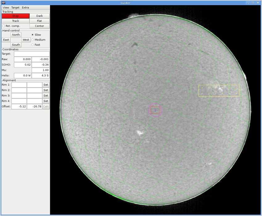
Hammerschlag et al.: Large-field high-resolution mosaic movies

                    Since it is always best to have a fast cadence when making                          a predefined maximum deviation dmax , the next coor-
                movies, the overlap between images in a mosaic should be as                             dinate-pair is given the same coordinate-number as the
                small as possible because this reduces the number of images                             one it is close to. If it is not close to any previous coor-
                necessary to cover a certain area. Due to the use of an equa-                           dinate-pair, it is given the next available coordinate-
                torial mount at the DOT, the “up” direction in the recorded                             number.
                images always corresponds to the direction of the earth north                        4. A histogram is made of each possible combination of
                pole and there is no diurnal rotation of the solar image. When                          two coordinate-numbers against how often these two
                using an alt-azimuth mount, one has to account for image                                coordinate-numbers are exposed directly after each
                rotation when making mosaic movies. The presented algo-                                 other.
                rithm is able to handle this image rotation. This has been
                                                                                                     5. Using this histogram, for each coordinate-number i,
                demonstrated on the Swedish Solar Telescope (SST).7
                                                                                                        the most likely successor coordinate-number NðiÞ is
                However, larger numbers of image fields are necessary to
                                                                                                        determined. If the contribution of this successor coor-
                cover a specified mosaic field due to the image rotation.
                                                                                                        dinate-number is less than 50 percent, it is discarded.
                    To ensure individual images can be aligned to each other,
                it is best to point the telescope in a boustrophedonic pattern                       6. Consecutive coordinate-numbers form a cycle if, when
                (making alternate linear scans in opposite directions), such                            starting at i and following the most likely successors
                that, there is always overlap at one of the edges between                               NðiÞ, NðNðiÞÞ, et cetera, one ends back at i. Distinct
                two consecutive images, except for when the telescope has                               cycles are given a number as well. The first coordi-
                reached the last point of a cycle and moves back to the first                           nate-number belongs to the first cycle numbered one.
                (see Fig. 1).                                                                           Then, every following successor coordinate-number
                                                                                                        NðiÞ, NðNðiÞÞ; : : : also belongs to cycle number one.
                                                                                                        The next coordinate-number that does not belong to
                3 Method                                                                                the first cycle then belongs to cycle number two, and
                An algorithm is presented that, fully automatically, creates                            so on.
                mosaic movies from a given set of images and a guider log
                without having to manually specify any information about                             After a mosaic cycle has been found, the images are
                the mosaics.                                                                      aligned using the following algorithm:
                   The algorithm for determining mosaic cycles is as
                follows:                                                                             1. Images are prealigned using the coordinates from the
                                                                                                        guider log.
                    1. The list of images is sorted by time.                                         2. The optimal alignment between pairs of overlapping
                    2. For each image, the pointing coordinates at the time of                          images (both in time and space) is calculated using a
                       the exposure are retrieved.                                                      cross-correlation algorithm.
                    3. Similar coordinates are given a unique number. The                            3. For each overlapping pair, a virtual spring is created
                       first coordinate-pair is given the coordinate-number                             between the two images which has a rest length that
                       one. The next coordinate-pair is compared with the                               corresponds to the optimal alignment of the pair and a
                       previous coordinate-pairs. If the distance is less than                          configurable spring constant (see Fig. 2).

                Fig. 1 A boustrophedonic pattern, making alternate linear scans in
                opposite directions, is a good way to create a mosaic. At the bottom              Fig. 2 Springs between images in a mosaic movie. The upper-left
                row, the telescope moves to the right after each image. At the end of             orange area is the first mosaic of a 2 × 2 image mosaic movie.
                the row, the telescope moves one image up, then continues to the left,            Horizontal and vertical black springs connect images neighboring
                and so on. In this way, there is always overlap between consecutive               in space. The lower-right green area is the second mosaic. The diago-
                images in one mosaic.                                                             nal red springs connect images neighboring in time.

                Optical Engineering                                                       081603-3                                             August 2013/Vol. 52(8)

Downloaded From: https://www.spiedigitallibrary.org/journals/Optical-Engineering on 09 Aug 2021
Terms of Use: https://www.spiedigitallibrary.org/terms-of-use
Hammerschlag et al.: Large-field high-resolution mosaic movies

                    4. In a loop, the forces exerted by the springs on all the                       • Springs with normal spring constants that couple
                       images are calculated and the images are moved a frac-                          images to their direct neighbors in space, however, the
                       tion in the direction proportional to the force. This is                        strength should also be inversely proportional to the
                       repeated until the amount of movement drops below a                             time between the exposures of those images.
                       certain level or until this step has been repeated a fixed                    • Springs with strong spring constants that couple
                       number of times.                                                                images to their direct neighbors in time.
                    5. A bounding box is calculated for the entire mosaic                            • Optionally, if there is a specific region of interest in
                       movie and all the images are shifted such that the                              which image motion should be minimized, the spring
                       top left corner of the bounding box is at coordinates                           constants between images neighboring in time in that
                       (0,0).                                                                          region should have an even stronger spring constant.
                    6. For each mosaic, an initially completely transparent                            Consequently, the surrounding images will then
                       frame is created with the same size as the bounding                             move more strongly.
                       box around the whole mosaic. Each image is placed
                       at the calculated position in that frame.                                        For an N x × N y × N t image mosaic movie, where N x is the
                                                                                                  number of images in the horizontal direction, N y in the
                    7. Within each mosaic of the mosaic movie, the images
                                                                                                  vertical direction, and N t the number of mosaics in the mosaic
                       created in the previous step are blended together using
                                                                                                  movie, there will be approximately 3 N x × N y × N t springs.
                       Enblend.8
                                                                                                        For each image i, we keep track of the estimated position
                    8. From the individual mosaics, a movie is created using                      r~i , that initially is set to be equal to the position according to
                       a movie creation tool such as Mencoder.9                                   the guider log. For each of these springs, the spring force
                                                                                                  between images i and j is F~ij ¼ kij ðr~ij − R~ij Þ , where r~ij ¼
                   Due to seeing, each image will be distorted slightly
                                                                                                  r~i − r~j is the estimated distance vector between the two
                different and, even after a perfect alignment of whole images,
                                                                                                  images, R~ij is the optimal distance between the two images
                distortions inside individual images in a mosaic movie will                       according to the cross-correlation algorithm, and kij is the
                result in visible image motion in the movie. This can be
                                                                                                  spring constant for this pair. After calculating all the forces,
                reduced by splitting images in sets of smaller, overlapping
                                                                                                  we calculate an improved  P        estimate of the position of the
                patches. These patches can all be coupled to their neighbors                      images: r~i0 ¼ r~i þ c j F~ij , where c
Hammerschlag et al.: Large-field high-resolution mosaic movies
a rectangle around the desired region. Subsequently, the pro- 1.0 nm, (ii) blue continuum 431.9, width 0.6 nm, (iii) Ca
gram calculates the required number of telescope fields-of- II-H 396.87 nm, width 0.13 nm tunable to blue by tilt, (iv)
view and the coordinates of each field to be successively Ba II 455.4 nm, width 0.008 nm tunable −∕ þ 0.2 nm bire-
observed. fringent Irkutsk filter12,13 and (v) near Barium blue con-
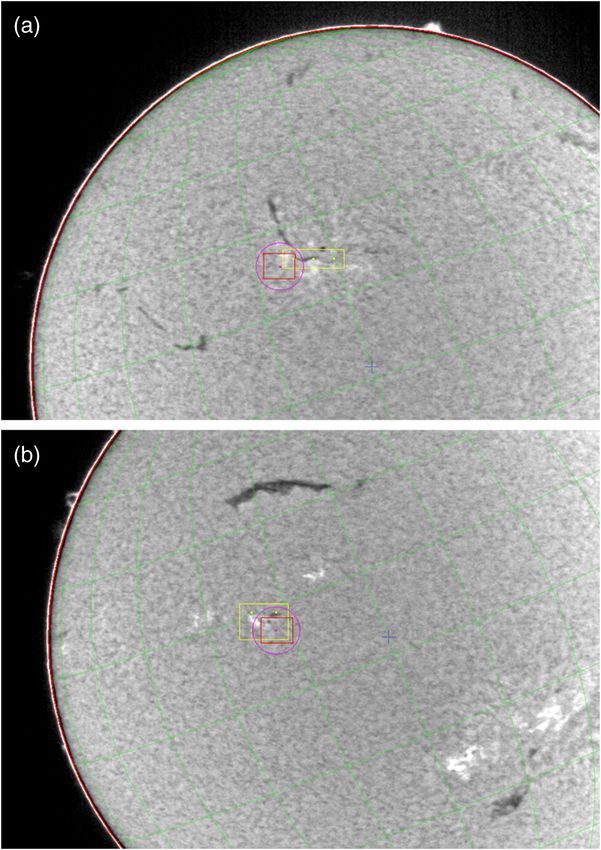
Figure 3 shows an example on an image from the guider tinuum 450.48 nm, width 0.54 nm or H-beta prominence
telescope of the DOT. The guider telescope is equipped with 486.23 nm, width 0.15 nm tunable to blue by tilt. The chan-
an Hα filter and electronic enhancement of contrast, of the nels, at the red side of the spectrum, are equipped with
image, for good visibility of filaments and prominences. ES4020 MegaPlusII Redlake cameras with a field of 113 ×
Bright-yellow lines indicate the chosen rectangle. In this 113 arcsec, 2048 × 2048 pixels binned 2 × 2 to effective
example, the calculated number of fields is 12 in the east- 1024 × 1024 pixels of 0.11 × 0.11 arcsec. These channels
west direction six, and in the south-north direction two are (i) Hα 656.28 nm, width 0.025 nm tunable −∕ þ 0.8 nm
(north is on top, east at the left, like in the hand-control panel birefringent Zeiss filter14 and (ii) red continuum 655.05 nm,
on the left side of the image). The calculated centers of the width 0.24 nm or Hα prominence 656.35 nm, width 0.23 nm
fields are indicated by bright-yellow points. tunable to blue by tilt.
During its exposure, the first mosaic field is shown in the The image b, in Fig. 3(b), shows the guider image during
bottom-left corner of the total mosaic field in Fig. 3(a). The the exposure of the second mosaic field. The dark-red boun-
boundaries of this field are indicated by a dark-red rectangle dary of the rectangular field is shifted one position to the
corresponding with the smallest camera field currently in use right, to the west. The observer can follow how the field
of 91 × 72 arcsec, being 1300 × 1030 pixels, hence, pixel is moving along the programmed path starting at the
size 0.07 × 0.07 arcsec. The small dark-purple circle indi- bottom-left corner, then moving one-by-one to the right,
cates the target position for tracking. in this case, six positions then one position upward, followed
The DOT is equipped with a multi-channel system. by moving back one by one to the left. In this example, there
The channels, at the blue side of the spectrum, are equipped only are two rows. In case of more rows, the field continues
with KPF100 Hitashi Denshi cameras. At present, the wave- by going up one position at the left side followed by going
lengths of these channels are (i) G-band 430.5 nm, width step by step to the right and so on, as already explained in
Fig. 1. When the last field is reached, the telescope automati-
cally moves to the first field at the bottom-left corner.
Originally, the program was developed with a square
region of interest in mind, such as 2 × 2, 3 × 3 or 4 × 4 fields.
In the case of an elongated region, it would be better to go
step by step along the shortest side of the region instead of
along the longest side. This will give the best fit of the field
boundaries to each other because the maximum time differ-
ence, between neighboring fields, is minimized. The pro-
gram will be improved in this way for future observations.
The DOT has an equatorial mount. Consequently, the
boundaries of the camera fields do not rotate relative to the
solar image. This is comfortable, especially during long-term
mosaic movies over several hours. Alt-azimuth mounts show
relatively fast image rotation in the neighborhood of the
zenith position. Hence, such rotation will be maximal during
the hours around noon in summer. Of course, this could be
overcome by an image rotator which requires additional opti-
cal surfaces and a precision drive system. The camera-field
boundaries at the DOT are oriented east-west and north-
south. This is convenient both for east-west strips (as in
our example) and for north-south strips. In practice, these
strips can be valuable for filament observations with the
Hα filter tuned to several spectral-line wing positions (a cer-
tain distance to the Hα line center corresponds to a certain
line-of-sight velocity). Flows, parallel to the solar surface,
have a line-of-sight and transverse component except under
specific limited circumstances when the flows are entirely in
the plane of the sky. The selection of a line-of-sight velocity
value can be helpful to find gas streams with certain veloc-
ities along the solar surface.
The large dark-red circle along the rim (see Fig. 3) indi-
cates that the main telescope is precisely following the Sun,
by use of an active system, which processes the solar rim
Fig. 3 Guider-telescope images of the whole sun with a mosaic field
of six by two fields. Image (a) taken during the observation of the first
position information of the guider. The guider image can
sub-field of the mosaic. Image (b) taken during the second subfield be observed in full screen, see Fig. 4, to allow a better obser-
observation. The array of bright points indicates the subfield centers. vation of objects of possible interest on the solar disk and at
Optical Engineering 081603-5 August 2013/Vol. 52(8)
Downloaded From: https://www.spiedigitallibrary.org/journals/Optical-Engineering on 09 Aug 2021
Terms of Use: https://www.spiedigitallibrary.org/terms-of-useHammerschlag et al.: Large-field high-resolution mosaic movies
coordinate system is visible. The position of the main tele-
scope is visible in Fig. 4 at the disk center indicated by the
purple circle and red camera-field boundary.
4.2 Application Examples
The mosaic-movie technique is extremely useful in correctly
identifying and analyzing the dynamics of solar features as
we illustrate by referring to common solar features seen in
Fig. 5. This mosaic consists of 12 fields from a mosaic movie
in the Hα line center, as described above. It was recorded
during the 2010 DOT Prominence Project by a team of col-
laborating solar researchers (PROM) coordinated by Helio
Research15 in La Crescenta, California. Successive mosaics,
of this area, were recorded during 10 days for the purpose of
observing filament channels and filaments forming around
the periphery of two relatively new, small active regions.
One new filament channel is designated by three arrows and
Fig. 4 Full-screen guider image for a better visibility of objects of inter- a label in Fig. 5 at the left (eastern) side of the mosaic. This
est. The dark red ring at the rim is absent because active guiding is filament channel contains a small filament in its initial stage
switched off. Details outside the rim, like prominences, are better vis- of formation. Several other filaments are shown by arrows
ible by use of electronic enhancement. The main telescope is pointed
to the disk center.
and labels. All are in filament channels, or zones, where
the magnetic field of the central part of the channel is parallel
with the long axis of the filament. The pattern of fibrils, typ-
the rim. Before the start of the mosaic observations, the main ical of a filament channel, can be seen in the filament channel
telescope can follow the sun passively by use of only coor- in the left side of the mosaic image in Fig. 5. The fibrils align
dinates. The broad red ring disappears and what remains is a end-to-end along boundaries where the line-of-sight compo-
thin bright ring which is due to electronic enhancement of the nent of the magnetic field direction changes sign from out-
region outside the rim for a better visibility of the prominen- ward to inward. This is seen when Fig. 5(a) is compared to
ces. Exactly at the rim, a narrow green ring of the solar Fig. 5(b). Similar major channels, of realigned fibrils, are
Fig. 5 (a) Mosaic of 6 × 2 images in the Hα line center from a mosaic movie over 5.5 h on this same area. This image was taken at 11:29 UT (10:19
local solar time) 0.2 h after the start of the mosaic sequences of images. Movies are an important asset to correct identifications of all of these
dynamic solar features which change at different rates. The main subjects are two “active regions,” one left of center, and the other right of center.
Each active region consists of bright areas called “plage.” Within these brightened areas, are sunspots which are the compact, nearly round, dark
areas. Everywhere around the plage and sunspots are elongated, thread-like structures known as “fibrils” which are organized in patterns around
the plage and sunspots because they follow the direction of the local magnetic field. The organized fibril patterns enable the identification of the
boundaries of the active regions which are often also marked by dark “filaments.” Mosaic movies were taken of these two regions to study the
formation and evolution of filaments that develop in and around the active regions. The filaments are designated by arrows with the exception of
the arrow furthest to the right side of the image which points to a short-lived feature called a “surge.” In a single image, a narrow “surge” of mass
along the local magnetic field can appear similar to a filament, but a surge is a temporary ejection of mass lasting minutes whereas filaments are
longer-lived dynamic structures that develop specifically at boundaries where the local magnetic field has a sharp reversal from positive to negative
polarity. (b) Magnetogram of same region at same time with SDO (Solar Dynamics Observatory) in space. Noticeably the DOT mosaic has a higher
resolution: pixel size 0.1 arcsec at DOT, 0.5 arcsec at SDO.
Optical Engineering 081603-6 August 2013/Vol. 52(8)
Downloaded From: https://www.spiedigitallibrary.org/journals/Optical-Engineering on 09 Aug 2021
Terms of Use: https://www.spiedigitallibrary.org/terms-of-useHammerschlag et al.: Large-field high-resolution mosaic movies
expected to form between the two active regions over the The time interval between successive mosaic images in
course of several days and later between the sunspots within this example, 6 min 36 s, comes about as follows. The Hα
each active region. line was sampled at seven spectral positions which are the
An example of a surge is shown by the arrow that is fur- line center and alternating at three positions in the red and
thest to the right in Fig. 5. Surges are short-lived ejections blue line wing. At each spectral position, 20 short exposures
that emanate from specific locations that are often close were made. Strictly simultaneous, there were 7 × 20 ¼ 140
to flare footpoints in the Hα chromosphere. Their curved tra- exposures in the nearby red continuum and other channels, in
jectories indicate that their flows follow the local magnetic this case the G-band, blue continuum and Ca II-H. The red
field and reveal the degree of local field curvature. The exam- continuum images are used for Keller-Von der Lühe speckle
ple, in Fig. 5, has little obvious curvature as it follows the reconstruction16 of the Hα images leading to images with
nearly radial fibrils around the periphery of the closest sun- diffraction limited resolution of 0.3 arcsec. This process is
spot. As in this case, in a single image, a surge can roughly computer-time consuming for movies and has not yet been
resemble a filament, however, in the movie, this surge is carried out. The frame-selected images, that are shown here,
readily distinguished from filaments because its flows are are the best of each sample of 20 images. The time required
more rapid and shorter-lived than the typical flows in fila- for the 140 exposures per field position is 30 s including the
ments. It is seen, that the surge is no longer present in the time needed for tuning the Hα filter. The repositioning time
series of three images, shown in Fig. 6, at a later time during of the telescope is 3 s. Hence, the cycle time per subfield is
the same day. 33 s, in this case, and mosaic cycle time is 12 × 33 ¼ 396
The time between successive images is 6 min and 36 s, as sec ¼ 6 min 36 s. The additional time needed for the longer
shown in Fig. 6. The contrast of the structure, in the field way from the last image to the first image of the next mosaic
around the flare, is seemingly lower in the bottom mosaic is so small that it is taken within the redundancy time built in
than in the two previous ones. This is because the program, the 3 s motion time per step. All motions are shock-free with
to represent the mosaic on the screen, has an automatic con- gradual increase and decrease of the accelerations by the
trast adaption to be able to clearly show the full range of servo system. Longer slew distances can be obtained in short
intensities in the image, especially during a solar flare. time by reaching high velocities without shocks. The same
technique is used for fast tuning of the Hα filter.
The Keller-Von der Lühe speckle reconstruction requires
at least 20 images at each Hα tuned position and about 100
images in the red continuum. This results in the following
other often used tuning modes of the Hα filter including five
spectral positions with each 20 images for a total of 100
images with 22 þ 3 ¼ 25 s cycle time per subfield, 3 posi-
tions with each 34 images for a total of 102 images with 19 þ
3 ¼ 22 s per subfield, 2 positions with each 50 images for a
total of 100 images with 16 þ 3 ¼ 19 s per subfield, and
direct 100 images with 13 þ 3 ¼ 16 s per subfield.
Surges and small flares frequently occur in and around
sites where new magnetic flux is developing. It is now
common knowledge that sites of new magnetic flux are
marked, in Hα images, by sets of closely spaced dark fibrils
such as the set on the opposite side of the sunspot from the
surge and below the filament in the right side of Figs. 5
and 6. These fibrils are much darker and are changing
more rapidly than the fibrils between the sunspots in the
active region in the left half of Figs. 5 and 6. The sets of dark
fibrils are named “arch filament systems.”17,18 These arch fil-
ament systems, in the active region in the right side of Fig. 6,
are dark because they are Doppler-shifted in varying degrees
in relation to the magnetic flux emerging beneath them. They
are seen as Doppler-shifted features, in Fig. 7, which shows
two pair of images at wavelengths a little greater and lesser
Fig. 6 Three successive images from the same set of 12 fields-of-
view as in Fig. 5 at 4.7 h after the start of the observations on this than the Hα centerline images in Figs. 5 and 6. The first pair
day. The fibrils between the sunspots are one of the special subjects is at Hα −0.04 and þ0.04 nm from the line center wave-
of interest. If they are dark and are changing rapidly, as within the length of the Hα line at 656.28 nm. On average, the Doppler
plage to the left of the large sunspot in the active region in the right shift, seen at −0.04 and þ0.04 nm, is 18 km∕s toward Earth
side of these images, they will have larger Doppler shifts than other
fibrils. These large Doppler shifts are a characteristic property of loca- and 18 km∕s away from Earth. The second pair shows
tions where new magnetic flux is welling up beneath the fibrils. The higher velocities which on average are −32 and þ32 km∕s,
dark fibrils are called “arch filament systems.” All active regions begin respectively, toward and away from Earth. Some of the arch
as “emerging flux regions” beneath arch filament systems which fre- filaments are seen to have these higher velocities which dis-
quently recur within existing active regions. The interactions of the
new and pre-existing magnetic fields frequently produce flares. The
tinguish them from ordinary fibrils.
new bright structure seen only in the third images is a solar flare Small solar flares often occur around arch filament sys-
first seen in its early stage of development in the middle image. tems, especially around sites where one polarity of the new
Optical Engineering 081603-7 August 2013/Vol. 52(8)
Downloaded From: https://www.spiedigitallibrary.org/journals/Optical-Engineering on 09 Aug 2021
Terms of Use: https://www.spiedigitallibrary.org/terms-of-useHammerschlag et al.: Large-field high-resolution mosaic movies
Fig. 7 The mosaic at the time of the brightening in four wing positions Fig. 8 The mosaic 6.6 min earlier does not show the flare seen also in
of the Hα filter, from top to bottom at þ0.04, −0.04, −0.07, and the Hα wings in Fig. 7. Hα wings from top to bottom: þ0.04, −0.04,
þ0.07 nm. The flare in Fig. 6 is seen here in the near wings of Hα −0.07, and þ0.07 nm.
in the upper pair of images below the dark arch filaments system.
The flare is not seen further into the wings in the pair of images at
−0.07 and þ0.07 nm but a few arch filaments and filaments are visible the gas streams originating low in the solar atmosphere,
due to their relatively high velocities. low-chromosphere and photosphere. The brightenings are
eye catching but the longer-term development of the region
is important and can be followed by the dark structures of the
magnetic fields pushes into the surrounding magnetic field of gas streams along the magnetic field lines. The farther away
opposite polarity. Such a flare is seen in the bottom image of from the line center, the higher the velocities are. The wing
Fig. 6 on and around the periphery of the arch filament sys- positions, at þ and −0.07 nm, also show as dark structures
tem. The flare is a newly brightened area on and below the the smaller-sized regions with higher velocities, respectively,
arch filament system. The flare is also seen in the top pair of down and upward for þ and − wing positions. Also, some
images in Fig. 7. The flare is nearly identical in both images higher-up gas streams, with high velocity, are visible. The
and this is evidence that the flare brightening is spectrally fast change of the far-wing structures is notable and typical.
broadened and does not reveal Doppler shifts. Figure 8 The time of 6.6 min between successive mosaics is too long
contains the set of images that immediately preceded to follow these fast changes in time in detail. Smaller
those in Fig. 7 for each wavelength and no flare is seen mosaics would take less time. Figure 9 shows the choice
in this set. Figure 8, in comparison with Fig. 7, also reveals on the guider disk of two smaller regions. In Fig. 9(a), a
the Doppler shifts in the filaments quite clearly. Unlike the region of three by one fields and in Fig. 9(b), an image
flare, we do not see the same filament structure in the two of two by two fields. It is the task of the observer to choose
wings of Hα. This is typical because filaments have continu- the best combination of field size and time resolution
ous mass motions and, therefore, their structure is slightly depending on the intended science.
different in each set of images separated in time by minutes. Figure 10 shows an example in which the choice was to
The movies, from which the images of Figs. 6–8 are taken, make a mosaic after a high-time-cadence single-field movie
can be found on the following website: http://dotdb.strw of an interesting part of the filament where many of its
.leidenuniv.nl/ftp/DOT/2010/2010-11-13/mosaic/. threads appear to connect to small-sized areas with strong
Among the direct eye-catching features are those with magnetic fields. Figure 10(a) shows a long filament in a
the greater visibility of the brightening in the blue (negative) mosaic of a north-south strip which, in this case, is speckle
wings, which means in the gas streams toward us. The reconstructed. The gap in the center part is interesting
positions, in the wings farthest away from the line center because of the many filament threads going downward
at þ and −0.07 nm, show the small-sized foot points of into the gap and to the sides, the so-called barbs of the
Optical Engineering 081603-8 August 2013/Vol. 52(8)
Downloaded From: https://www.spiedigitallibrary.org/journals/Optical-Engineering on 09 Aug 2021
Terms of Use: https://www.spiedigitallibrary.org/terms-of-useHammerschlag et al.: Large-field high-resolution mosaic movies
Fig. 9 Choice of two smaller mosaic regions on the guider image.
(a) Region of 3 × 1 camera fields. (b) Region of 2 × 2 camera fields. Fig. 10 (a) Mosaic of whole filament, top is north. (b) Three succes-
sive image combinations with time intervals of 30 s.
filament, where the small brightenings hint at small-scale
magnetic reconnections in the lower atmosphere. The erup-
tion of this filament was observed the next day, 7 October
2004, at Helio Research in La Crescenta, California and
the eruption appeared to begin at the site of the gap. Movies,
at the DOT in time cadence of 30 s, were made of a single
camera field centered on this filament gap. Movies from
08:47 till 09:42 UT were speckle reconstructed. Three succes-
sive image combinations are shown in Fig. 10(b) at 09:32:00,
09:32:30 and 09:33:00 UT. Each image combination consists
of a G-band image at top-left, a Ca II-H image at top-right, an
Hα core image at bottom-right, and an Hα blue wing image at
−0.08 nm of line center at bottom-left. The Hα wing images
show the very fast changes in the high-velocity gas streams
in the solar atmosphere. The movie is available in avi, mov
and mpeg at the DOT website: http://www.staff.science.uu.nl/
~rutte101/dot/ or http://www.dot.iac.es.
Choose then “solar movies.” Direct link in, for example,
avi: http://www.staff.science.uu.nl/~rutte101/dot/albums/
movies/2004-10-06-filament-gb+ca+haw+hac.avi.
A possibility, for very high time cadence, is to split a full
burst of 100 to 140 images of the red continuum in not only
spectral positions of the Hα line but also in small time inter-
vals. For instance, the burst of 100 images in 13 s, without
tuning the Hα filter, can be split into five successive sub- Fig. 11 (a) Mosaic including whole filament channel with interesting
fast changes in high resolution but lower time cadence than for
bursts of 20 images, each in a period of 2.6 s. smaller field-of-view, observed by DOT. (b) Single camera field of
When two high-resolution telescopes are available, it is same interesting fast changes in high resolution and high time
possible to combine a single camera field showing unusually cadence, simultaneously by SST.
Optical Engineering 081603-9 August 2013/Vol. 52(8)
Downloaded From: https://www.spiedigitallibrary.org/journals/Optical-Engineering on 09 Aug 2021
Terms of Use: https://www.spiedigitallibrary.org/terms-of-useHammerschlag et al.: Large-field high-resolution mosaic movies
fast changes in high spatial resolution and high time cadence specialized tasks. Additional support for the DOT came
by one of the two telescopes with simultaneous mosaics of a from the Netherlands Organisation for Scientific Research
whole filament region around this single camera field by the NWO, the Netherlands Graduate School for Astronomy
other telescope. An example of such a co-observing by the NOVA, and SOZOU. We acknowledge the NSF Rapid
SST19 and DOT is shown in Fig. 11. These two neighboring Award AGS-1024793 that made the acquisition of the data
telescopes can take advantage of good seeing at the same at the DOT possible during 2010. The Rapid Award was
time for these combined observations. based on NSF Grant ATM-0837519 and SHINE Grant ATM
0852249 to Helio Research. We thank V. Gaizauskas to have
5 Conclusions made available to the DOT the Hα Lyot filter. The SST
The results, obtained with the observations recorded during and DOT are located at Observatorio del Roque de los
the 2010 DOT Prominence Project of the PROM team led by Muchachos (ORM) of Instituto de Astrofísica de Canarias
Helio Research, show the capability of a new method for pro- (IAC).
duction of large-field mosaic movies in high spatial resolu-
tion from frame-selected images that are already suitable for References
movies. The time cadence of a mosaic movie is lower than 1. S. F. Martin et al., “The link between CMEs, filaments and filament
that of a movie of a single camera field. The more camera channels,” Ann. Geophys. 26(10), 3061–3066 (2008).
fields necessary for the total mosaic field, the lower the 2. R. Szeliski, “Video mosaics for virtual environments,” IEEE Comput.
Graph. Appl. 16(2), 22–30 (1996).
resulting time cadence. The associated guider program offers 3. A. Rav-Acha et al., “Dynamosaics: video mosaics with non-chronologi-
the observer an excellent tool for choosing the best size and cal time,” in Proc. IEEE Comput. Soc. Conf. on Comput. Vis. and
Pattern Recognit., Vol. 1, pp. 58–65, IEEE, Jerusalem, Israel (2005).
location of the mosaic field depending on the structures on 4. R. J. Rutten, R. H. Hammerschlag, and F. C. M. Bettonvil, “The Dutch
the solar disk and the science plan. open telescope,” in Solar and Stellar Activity: Similarities and
Combinations of high-resolution mosaics, alternating Differences, C. J. Butler and J. G Doyle, Eds., Astron. Soc. Pac.
Conf. Series, Vol. 158, pp. 57–60 (1999).
with or concurrent with high-time-cadence movies of a sin- 5. R. J. Rutten et al., “DOT tomography of the Solar atmosphere. I.
gle camera field, have proven to be valuable for revealing fast Telescope summary and program definition,” Astron. Astrophys.
413(3), 1183–1189 (2004).
changes in specific small regions of interest within the con- 6. DOT website: http://www.staff.science.uu.nl/~rutte101/dot/ or http://
text of evolutionary changes more suitably observed in the www.dot.iac.es.
large mosaic fields. Sequential observations of a single field- 7. Swedish Solar Telescope website: http://www.solarphysics.kva.se.
8. Enblend, http://enblend.sourceforge.net/.
of-view and a mosaic series of images are demonstrated, 9. Mencoder, http://www.mplayerhq.hu/.
herein, using DOT observations of a single field-of-view 10. G. Sliepen et al., “Contactless sub-millimeter displacement measure-
on a gap in a filament and subsequent DOT mosaic obser- ments,” Proc. SPIE 7018, 70181C (2008).
11. H. Nobach and M. Honkanen, “Two-dimensional Gaussian regression
vations of the whole filament. Collaborative observations, for sub-pixel displacement estimation in particle image velocimetry or
using two telescopes simultaneously, one to observe a single particle position estimation in particle tracking velocimetry,” Exp.
field-of-view while the other concurrently records mosaics Fluids 38(4), 511–515 (2005).
12. R.H. Hammerschlag et al., “The Irkutsk Barium filter for narrow-band
around and including the single field-of-view, are promising. wide-field high-resolution solar images at the Dutch Open Telescope,”
An example of such a combination demonstrates high- Proc. SPIE 7735, 773585 (2010).
13. G. I. Kushtal and V. I. Skomorovsky, “Advancements in the geometrical
cadence observations of a small active region (SST) concur- measurements of the birefringent filter's crystal plates and two-dimen-
rent with mosaics of a large area around the active region sional measurements of Doppler velocity in the solar atmosphere,”
including an adjacent long filament channel containing a Proc. SPIE 4900, 504–512 (2002).
14. F. C. M. Bettonvil et al., “Tunable H-alpha Lyot filter with advanced
filament (DOT). servo system and image processing: instrument design and new scien-
tific results with the Dutch Open Telescope,” Proc. SPIE 6269, 62690E
Acknowledgments (2006).
15. Helio Research website: http://www.helioresearch.org/.
We are grateful to Rob Rutten for his suggestion to start 16. C. U. Keller and Lühe O. von der et al., “Solar speckle polarimetry,”
making mosaic movies and for his continuous interest in Astron. Astrophys. 261(1), 321–328 (1992).
17. A. Bruzek, “On arch-filament systems in spotgroups,” Solar Phys. 2(4),
the project. The Technology Foundation STW in the 451–461 (1967).
Netherlands financially supported the development and 18. A. Bruzek, “Motions in arch filament systems,” Solar Phys. 8(1), 29–36
(1969).
construction of the DOT and follow-up technical develop- 19. Y. Lin et al., “Small-scale, dynamic bright blobs in solar filaments and
ments. The DOT has been built by instrumentation groups active regions,” Astrophys. J. 747(2), 129 (2012).
of Utrecht University, the Central Workshop of Delft
University (now DEMO-TU-Delft) and several firms with Biographies and photographs for all authors is not available.
Optical Engineering 081603-10 August 2013/Vol. 52(8)
Downloaded From: https://www.spiedigitallibrary.org/journals/Optical-Engineering on 09 Aug 2021
Terms of Use: https://www.spiedigitallibrary.org/terms-of-useYou can also read