LEARN SHARE CREATE - September October 2021 Volume 2 No.5 Price $10 - Rail Modeller Australia
←
→
Page content transcription
If your browser does not render page correctly, please read the page content below
Price $10

  September October 2021   Volume 2 No.5

LEARN       SHARE          CREATE
A Train of Thought
                                                                 A group in model railways can take on many forms,
                                                                 they can be an organised club, regular “Round Robin”
                                                                 operators visiting the homes of friends or club
                                                                 members, or a small group working together to create a
Editor/ Publisher                           Robyn Taylor         layout for exhibitions. These groups can offer a great
                                                                 opportunity to learn from other modellers or perhaps to
Editorial Assistants                        Trevor Gibbs         share your skills and experiences. Being involved with
                                                                 others adds to the enjoyment and camaraderie that is
                                            Vivien Gibbs         found in our hobby. The benefit from the association
                                                                 with like minded people often develops an enthusiasm
Email                  info@railmodelleraustralia.com            to work on your own layout using the extra skills you
                                                                 have acquired.
Facebook                        Rail Modeller Australia          Confidence is strengthened by taking small steps and
                                                                 not being disillusioned when things don't work out as
Phone                                     0411 297 800           well as you would like. Communicating the problems
Rail Modeller Australia is available as a free                   you may be having with others in the hobby can often
download and is also available as a printed magazine             provide solutions and help to grow confidence in your
                                                                 skills. We are fortunate that we now have a plethora of
for those who prefer that format. The printed version            information and tutorials available across a number of
will be at a cost of AUD$14.00 which includes                    platforms and they are a valuable resource...but, action
postage within Australia. Information for overseas               and practice builds skill. We all start out as beginners
postage is available by contacting us via our email              and you should take pride in what you achieve or
address.                                                         create but always believe in yourself and what you
                                                                 may be able to achieve as your skills and confidence
                                                                 grow.
DONATIONS
To help us to keep this as a free magazine we do need            This issue has a couple of 'how to' articles including a
financial support and donations can be made using the            venture into some simple electronics starting with the
                                                                 wiring of the signals we created in the last issue. As
paypal Donate Button on our website.                             time progresses we will provide other tutorials to
                                                                 further your involvement in the hobby. We might
ADVERTISING                                                      admire the work of others and think “I could not do
                                                                 that” but we should not be intimidated, as some of
We are happy to accept advertising in the magazine.              those layouts were built up over a long time. Our
For further information and pricing, please contact us.          hobby is a journey in itself, not an end destination and
                                                                 exercising our creativity and learning from others is
CONTRIBUTIONS                                                    the key to making the journey enjoyable and
                                                                 rewarding. Grow with the hobby and enjoy what you
Contributions are welcome and can be in the form of              do and if you have fun along the way, you are doing it
Articles, Photographs, Technical Information or other            right!
items related to the hobby of model railways. All
                                                                 Happy modelling!
contributions will be considered but may not be                  Trevor Gibbs
accepted for publication. All contributions must be the
original work of the author including photos which
should be identified with the maker’s name. The final
decision for publication of articles will remain with the      APOLOGY
Editor. For further information on providing articles
for the magazine, please contact us either by email or         In our last issue, we used a map of the Naracoorte South
phone.                                                         East Division drawn by Hugh Williams which was
                                                               originally published in the SARMA magazine "Buffer
COPYRIGHT                                                      Stop". We did trace over this map to produce the one in the
                                                               last issue with the relayed permission of Hugh.
The Rail Modeller Australia logo is copyright and may
not be used without the express written permision from         Unfortunately when we enlarged the map, Hugh's name and
the editor. This magazine and the contents are also            therefore his credit for the original was inadvertently "lost"
                                                               off the page for which we apologise. We also thank Hugh
copyright. Articles and other information provided,            for his good natured understanding in this matter. We are
remain the property of the original author and have            dealing with the famous Australian "tyranny of distance" the
been used within these pages with their consent.               fact being a drawing in SA that was enlarged in Victoria
                                                               before being retraced in Queensland and published.
Cover Photo: The former Railway Square shelter in Sydney.
The sydney tram waits patiently as travellers alight and new   Thank You again Hugh,
passengers board. Photo: Greg King
                                                               The Rail Modeller Australia team

PAGE 2                                       September / October 2021                            Rail Modeller Australia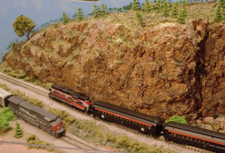
Contents
         6
                                        Greg King’s
                                        Sunbury Municipal
                                        Tramways Trust

                                    Whittington Falls and

    12                                  Three Doors
                                         Corio MRC

                                         Making Simple

    22                                 Searchlight Signals
                                          Trevor Gibbs

    24                                 Using a Multi Meter
                                          Trevor Gibbs

    30                                  Billandi
                                A new layout by Bill Cox                                                                       BILLANDI

                                        MAIL               DINING CAR         FEEDBACK CAR
                                                                                                   CABOOSE

     This publication nor the editor accept any responsibility for the accuracy or reliability of articles or advertising contained within these pages. We do not
     necessarily subscribe to the views or opinions expressed or implied by contributors or advertisers. The publication does not guarantee either expressed or
     implied to the good conduct or practices of those who advertise in this publication.We reserve the right at all times to refuse acceptance of material that is
     considered to be unsatifactory for publication.

Rail Modeller Australia                                       September / October 2021                                                                     PAGE 3
BRING THE            MAGIC OF
         TO YOUR LAYOUT OR DIORAMA
 SCALE CYCLISTS* ACTUALLY PEDAL THEIR WAY THROUGH LAYOUTS
   AND VEHICLES DRIVE THEIR WAY AROUND ROADWAYS WHILST,
     SPEEDBOATS OR YACHTS CAN CRUISE LAKES OR PONDS.
                  WORKS WITH ALL SCALES*

                 ONLINE SALES THROUGH

              WWW.MAGNORAILOZ.COM.AU
             CHECK OUT OUR YOUTUBE CHANNEL AT KLATCHCO56
                   *CYCLISTS AVAILABLE ONLY IN HO SCALE

PAGE 4              September / October 2021              Rail Modeller Australia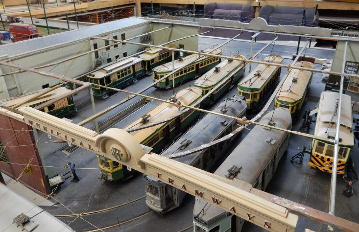
Rail Modeller Australia September / October 2021 PAGE 5
MT T
Greg King shares his story of modelling trams and provides a photographic essay of his extensive collection.
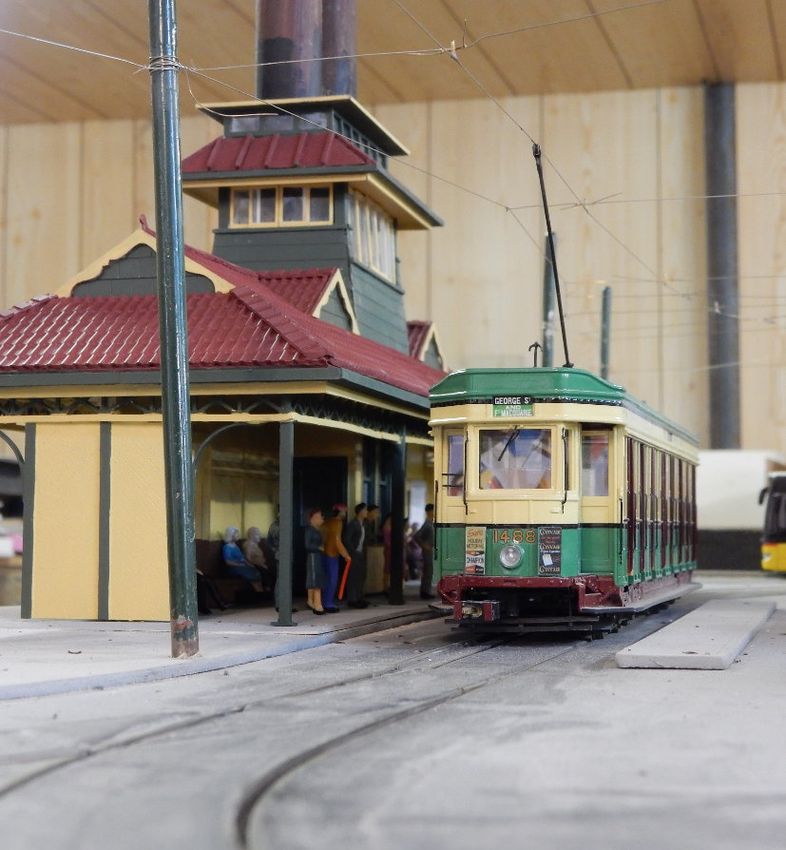
Above: A quartet of Sydney trams wait on shed for their next call of duty. The façade of the depot was created using parts cast
from old kits. The MTT emblem is made using an MTT (Adelaide) uniform coat button which was moulded and cast.
My modelling started when I was about 18 months in HO scale, all the while developing a skill based
old (I am now 70) when my parents bought me a on the belief that the next model had to be better
tinplate “Boomer” tram and I loved it. One day, I than the last. This philosophy is still true to this day.
was playing in the front yard in Parkdale and Mum
called me in for lunch. Of course, I left it out the In the late 70’s, I was living in Adelaide and
front and it was gone when I went back. I was became a motorman on the Glenelg line. I lived in a
broken hearted and longed for another model tram town house with not a lot of room. The State
Transport Authorities published a story on me and
but they were no longer available. the models in their in-house magazine.
As a result, I was asked to build a small operating
Life moved on and we eventually moved to North module for the up-coming Golden Jubilee of the
Fitzroy. I would watch the never ending parade of Glenelg line in 1979. It was displayed and operated
trams passing the front of our place but it was not in the Glenelg Town Hall.
until I turned about 15 that I started making model
trams. My “payment” for doing this otherwise “labour of
love” was driving which ever historic tram I wanted
The first very crude creations were made of balsa from the museum for the celebration. I spent weeks
wood and basic. Over the years I honed that into a of fun driving the F1 282, H1 381 and W2 294!
reasonable skill and made some reasonable models
PAGE 6 September / October 2021 Rail Modeller Australia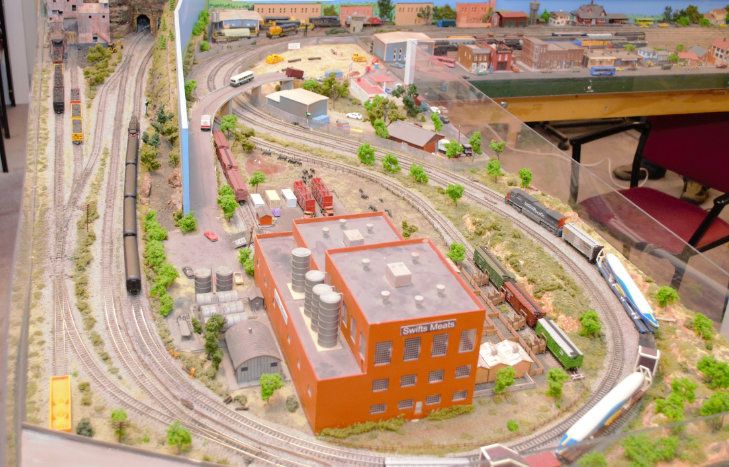
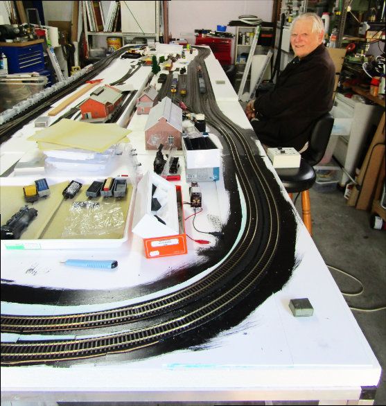
Eventually I moved back to Melbourne in the                       to build the empire I had always wanted. The old
1980’s and back to the trams there. It was not long               layout had to go! The garage which was a catch all
before I was approached by a gentleman from                       for everything, had to be emptied so I could build
Sydney to build him some O scale model trams.                     a proper base. I built a new shed for the general
This was my first foray into O scale and I never                  home workshop and non-model items, such as the
looked back.                                                      lawn mowers, saws and all the other things that
My first layout started as a straight end to end test             hinders our modelling time!
line in my old garden shed, not long after my wife
and I were married in 1982. In 1985 we moved to                   Fortunately, my friend Bill Parkinson from Sydney
Sunbury to a house with a large 2 car garage built                came to visit for a week and we both got into it and
on the back of the property. I built a small layout in            built a truly proper frame for the future layout. After
the garage which was only ever going to be the start              he left, I continued until all the base board was
of bigger and better things.                                      complete.

I doubt if it had ever seen a car and it never would              I had a few modelling jobs to do so not much
with me. This was going to be the new home for                    happened for about a year before the construction
the “Empire”! For many years, the original test                   crew of one (me), stepped in and started laying
track expanded with street paving and a loop at                   track with a vengeance. The layout is growing yet
one end, followed by a corner making it an L                      again with the next extension being to the narrow
shape with another loop, a car barn (depot)                       gauge section of the layout. I just hope I live long
followed. For 30 years or more, that was my                       enough to see it through to its full potential.
layout! It was pretty rough as there was no proper
base board built, just the “tops” were added to.                  As for the actual models, like most modellers, I
I expanded the garage and added a workshop                        have more kits than I can ever hope to build, I really
about 15 years ago. About 3 years ago, realising I                need to live to about 150 years old to get them all
was not getting any younger, I decided it was time                done!

Above: A Geelong Butterbox Tram sits on support jacks and the bogies have been removed for servicing. The attention to
detail captured in this scene is superb. The cabinets are well stocked with spares and everyone is quite busy. The shop foreman
is discussing the work requirements with the leading hand as the welder is masked up and ready to work. The floor mounted
point lever is another feature that adds to the overall scene.

Rail Modeller Australia                September / October 2021                                                     PAGE 7
Over the years I have produced many resin kits by       look from time to time and see what we have been
making patterns, rubber moulds and castings to pay      doing.
for my hobby. I sold many US kits over the years
and those kits have a good reputation in America.       The kits are complex looking but relatively easy to
                                                        build. I do the 2D drawings and Joe converts these
A few years ago, I partnered up with Joseph             to a 3D file and prints them. It might sound easy
Spinella in Sydney to produce model trams in 3D.        but it is actually quite a complex procedure. As you
Joe’s work is magnificent. Our latest creation is the   will see by the photos of some of our cars, the
SEC Maximum Traction Bogie cars (ex Hawthorn            results are really worthwhile as he has made some
Tramways Trust N class) which will be released          of the finest kits of trams available. This process, I
soon. Our site is: http://model-trams.com . Have a      believe, is the future for model trams.

                                                                         Above: With the roof removed we have a
                                                                         fascinating view of the interior of the
                                                                         depot.
                                                                         The Municipal Tramways Trust depot is
                                                                         a hive of activity with numerous trams
                                                                         being serviced or prepared for the days
                                                                         work.
                                                                         The attention to detail and the weathered
                                                                         appearance of the site and the stock adds
                                                                         a realistic appearance to the scene.

                                                                         Left: A Brisbane City Council drop
                                                                         centre tram number 293 negotiates the
                                                                         complex web of overhead wiring.
                                                                         The first drop centre car was built in
                                                                         1925 and they continued in production
                                                                         until 1939. 191 cars of the type were
                                                                         built.

PAGE 8                               September / October 2021                         Rail Modeller Australia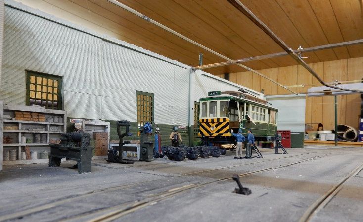
Above: Brisbane Phoenix class tram 547 is off shed and ready for a day’s work. In the shed, Brisbane Phoenix class 554 which
was the last tram to run in Brisbane sits next to its stable mate, a Brisbane Drop Centre 293. The Sydney R class tram 1763
has finished for the day as the driver heads off to the cribb room.

The “Get home faster by tram” decal was the creation of my friend Darren in Brisbane, a whiz kid when it comes to this sort
of art work. Greg designed most of the ads you see on the trams. Brisbane trams from the late fifties, had the ads sign written
on the car sides so they kept them (sometimes updated) all their lives. The individual ads really make a big difference to the
models.

History of the Brisbane Phoenix Class Trams
In 1962 a terrible fire destroyed the Brisbane City
Council tram depot at Paddington. A total of 65 trams
were lost in the disaster. To boost he fleet the Brisbane
City Council constructed eight trams using parts that
had been retrieved from the wreckage of the fire and
these trams were called Phoenix Class.
The Phoenix class trams were essentially an FM class
unit but featured some major improvements. The
padded seats, fluorescent lighting and timber
pannelling made these trams popular with Brisbane
commuters.
An upgrade of the wheel design helped to reduce noise
while travelling. The Phoenix class trams could
accomodate 110 passengers.
The class boasted a Phoenix bird logo under the
drivers cab window. Number 554 was the last one built
and was also the last tram to run in Brisbane on the
13th of April 1969
                                                                                                        Photo: Brisbane Courier Mail

Rail Modeller Australia                    September / October 2021                                                    PAGE 9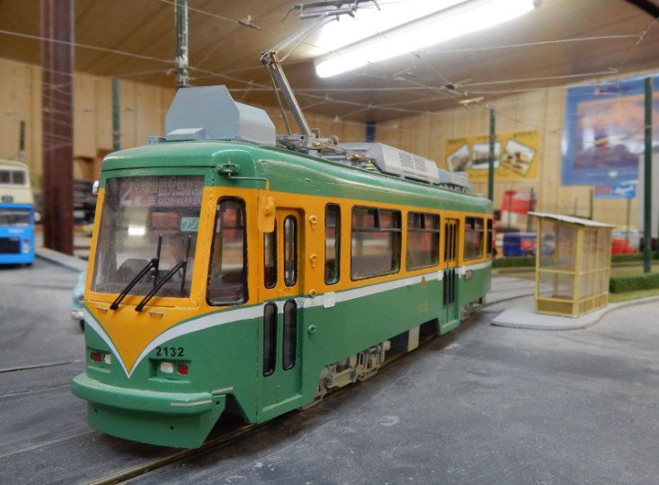
Right Top: A resplendent Japanese
Kagoshima tram.
Editor’s Note: Right Lower: An Auckland New
If you would like more information on Zealand 1930 series tram in red and
cream livery. These trams featured
trams there are a number of Tramway advertising boards on their roofline.
Museums around Australia and the World. The enclosed cabins would have
made them comfortable in inclement
You can find links to these museums on weather.
the Ballarat Tramway Museum Site.
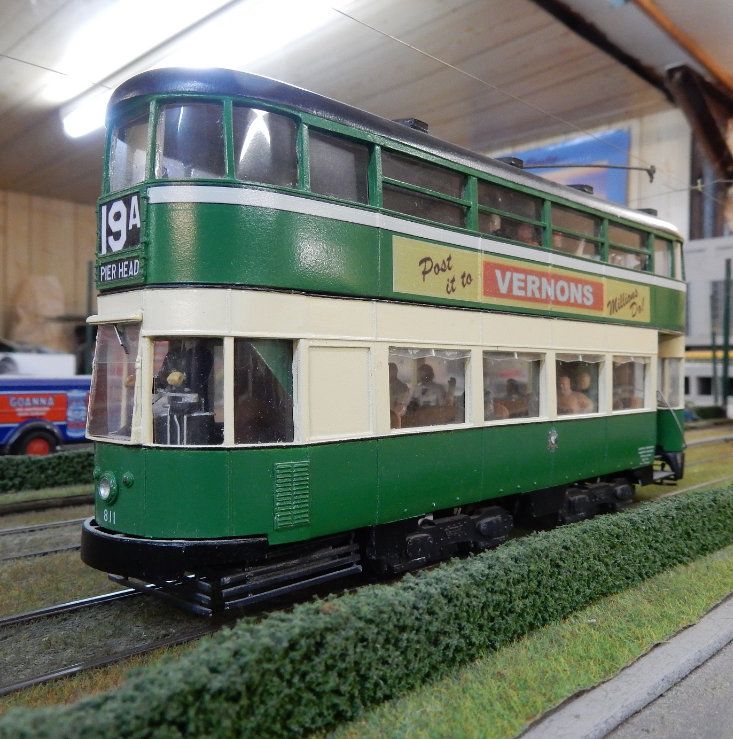
Below: Looking very smart in its
https://www.btm.org.au/links.html green and cream livery, this Liverpool
double deck tram was refered to as a
cabin car. Similar in design to double
deck buses with a spiral staircase
PAGE 10 September / October 2021 Rail Modeller AustraliaRail Modeller Australia September / October 2021 PAGE 11
WHITTINGTON FALLS

                The first of Corio Model Railway Club’s N Scale Layouts

                                                 By Alan Skipworth and David Cook
Corio Model Railway Club in Geelong, Victoria has       The layout is DC with control coming from a pair of
two American based N scale layouts, both of which       scratch-built controllers. All the points to the yards
are designed for continuous running.                    and crossovers are electric, with operators working
                                                        from behind the layout.
Alan and David tell us about the Corio MRC and
how these N scale railways were built.                  THE HISTORY OF “WHITTINGTON FALLS”
                                                        Back in early 2008, months were spent looking at
The Corio Model Railway Club in Geelong has been        numerous N gauge plans, drawing many alternate
running for over 50 years. Over that time, the club     plans, measuring the club room and dismantling the
has had different homes throughout the Geelong area.    very partly built layout that took up space in the
It is currently located at John St in Geelong West,     club room.
next to Baker’s oval.
                                                        Being a club layout, the builders consulted with the
Like all clubs, our members have a wide interest in     many well versed layout builders in the club. A final
all aspects of model railways, from the steam era to    plan was submitted to the Committee for approval
the modern day. Most members are building up their      which was granted with all in favour. Work began
skills through team work. All scales are represented,   immediately with sourcing of the timber required
although the Club has only two N scale layouts, one     for the table top and legs. By late May of 2008, the
of which is an exhibition layout and two HO/OO          N gauge layout was beginning to take shape.
layouts.

One HO layout is “running” and a new large layout is
currently under construction. The two N scale layouts
have been developed by the members over a number
of years, resulting in what you see today.

WHITTINGTON FALLS
“Whittington Falls” is an N scale layout named after
a former long time Life Member, the late Warwick
Whittington. This layout is a DC layout with 2
mainline tracks, a storage yard, and a station. The
layout has an overall size of approximately 2.8m x
                                                        A CSX GP40 pulls a passenger train of New Haven cars
4.5m. It was completely built from scratch in an L      while a Union Pacific GP20 takes a freight around the outer
shape to avoid an electrical panel in the Clubrooms.    loop.

It is run as a North American influenced layout and     During 2009-10, work continued with landscaping
represents the US/Canadian border. Trains from both     of the layout. We used some different techniques
countries can be regularly seen on the layout. The      depending on what materials were available. Most
backdrop is very mountainous, with a covering of        of the base was polystyrene which was covered by
pine trees as the major industry in the town is a       wipes soaked in plaster.
sawmill.

PAGE 12                              September / October 2021                          Rail Modeller Australia
For example, one of the tunnels was a mailing tube
cut in half and then covered.
Art Courtney lent a hand in the painting of the
mountains as he tried out an idea he had read about.
Art writes - “The scenery technique is called Zip
Texturing. Brown wood dye powder was mixed with
water and then brushed across the plaster hills to
give a base soil colour that was darker in the
ravines.
This was followed by a green dye that simulated a
grass cover. The whole exercise takes a matter of “Whittington Falls” station area at the viewing front of the
minutes and serves until more time can be spent on layout. The railway has plenty of traffic but is not “filled to
the brim” with rollingstock. The road at the front will climb
covering scenery in ground foam. the hills to the back where you can just see the bridge at the
top left. A timber truck is negotiating the secondary road
Editors Note - “Zip Texturing” was a phrase coined down the hill
by Linn Westcott, the editor of “Model Railroader”
magazine in the 60’s and 70’s and one of the most The road was continued around the edge of the
prolific innovators in this hobby at that time. layout before going under the trestle bridge. The
road continues past the saw mill and silo area to
After the winter break, it was back to landscaping another bridge up over the tracks and off into the
again. mountains.
This is the right hand side of “Whittington Falls” with our
passenger train passing the lumber yard and silo area. The
painted silos with murals are typical of many silos around The background is very effective here with two lighter tones
of a light brown colour and a green/greyish tinge. This is so
the country which have become local tourist attractions.
simple in conveying a sense of distance, but it only requires a
The spaced out nature of this area is very typical of an basic outline that just about anyone could do.
industrial area rather than a crowded out scene. A picture of
Warwick Whittington is overseeing the scene as a reminder
of a valuable lost member of the Corio MRC.
The backboards and mountains were made for the
corner and the right end. The colouring of the river
and lake was also made ready for the liquid river to
be poured. At the other end of the layout the small
bridge was made over the 2 tracks near the back
corner.
The road was continued over the flat hill and
another bridge brought the road down to track level
just prior to the station. The left hand side of “Whittington Falls”. Note the different
earth colours and textures over the range of the scene.
Rail Modeller Australia September / October 2021 PAGE 13David Cook stands proudly as part of the two man team with
A longer view of the Whittington Falls station area showing Les Marsh who built “Whittington Falls” with scenic input
the “highway” or main road as well as the secondary roads. from Art Courtney.
The “Inner track”, just visible to the right of the timber truck,
climbs over the tunnel mouth. In the mean time, a train on the
outer track will make a short appearance on the track at the
base of the hill.
A few moments later and the CP Rail freight makes a cameo
appearance between the two lower level tunnels while the
Passenger train passes the station. Casual observers are
“There was movement at the station… “ in fact quite a lot of often left wondering “How did that train face that way?”
movement with a Canadian Pacific (CP Rail) double stack
container train, ready to run the railway through while a
Union Pacific (UP) passenger special is pulling into the
station. The UP GP20 (General Purpose 2000 Horsepower) is
waiting its turn to stretch its legs around the layout.
Fig. 3 All ready to go!
An Oil Depot and Container port were to be central to this
part of the layout. We had purchased a Timber Mill kit to use
in the middle of the layout but its footprint way too big for
the intended position on the layout so the location was
The CP Rail freight is entering the station while the Special is changed.
negotiating the trestle bridge. David Cook made a special jig
for the trestle bents on his own layout, so he used it for this One line of track was lifted and re-laid further back to allow
layout as well. trains to have access to the mill. An area was made for
warehouses at the front.
David’s own layout “Maple River Junction” will hopefully
appear in a future issue of Rail Modeller Australia. The area at the left which was going to be an oil depot
became a small grain terminal with silos.
PAGE 14 September / October 2021 Rail Modeller AustraliaLeft - The Passenger Special is starting its
descent into the “Whittington Falls station yard
area.
The curves are broad and flowing which gives a
sense of distance. This hides the true length of
the layout because the viewer does not have two
straight lines (the backdrop and a straight
section of track) to gauge the length.
This is one way to make a layout look longer
than it is, by using a very long radius curve or
an “S” bend rather than a geometric straight.
A deviation of just 25 to 30 mm over a metre (1”
in 36”) or so will work a visual treat!
Right - You can almost hear the dynamic brakes
start to scream as the passenger cars push the
locomotive down the hill and the engineer is
making a safe descent of the gradient.
Foliage also breaks up the visual cue of space and
helps make any layout appear bigger than it is.
Note how the texture down the hill subtly changes
tone entirely.
Dynamic Brakes are a way of using the electric
traction motors instead of air brakes to slow and
hold back the speed of a train. The prototype
operation of trains will be a future article in Rail
Modeller Australia.
Left - Almost down the hill. The second unit is a steam
generator car, necessary for the passenger cars because the GE
Dash 8 locomotive was not purpose built for passenger trains.
The steam generator serves much the same purpose in North
America as power cars do in Australia. They provide power and
heat for the train using high pressure steam generators instead
of diesel powered alternators.
Right – The CP Rail freight is at the “polar” opposite end
of the layout by the timber mill and under the road bridge.
The bridge would make a great viewing spot. Like many
North American bridges, there is no provision for foot
traffic, making watching trains just that bit more
“interesting”.
Rail Modeller Australia September / October 2021 PAGE 15THREE DOORS
The N scale Exhibition Layout of Corio Model Railway Club
By Alan Skipworth
THREE DOORS
The name “Three Doors” suggests that it was built
on three doors on “U” shaped framework. In reality,
it is two recycled doors plus another section to make
it the same size as three! Alterations and
modifications have changed the original track plan
into a double tracked mainline. This allows for
continuous running of trains.
On the layout, there are sidings that allow the club to
park boxcars and the like around the track. There is
also a loco repair shed and museum, which shows
off some of the club rolling stock. The shape has
allowed the layout to represent a mid-west American
region, with farm land, an industrial area and a town
centre area.
The train is passing a work crew, who have stepped back to
allow safe passage of the train. The prefabricated track on the
flat car is quite common in North America for quick track
repair. The heavy road crane would be used to lift the old
sections of track out and help with installing the new. On the
road further up the hill, a car has hit a power pole, having
lost traction on the road. The driver is inspecting the damage.
There are various mini scenes and details of interest
to keep spectators looking at the layout. There is a
marching band parading down the Main street, a
house on fire, mountain climbers, people swimming
in the river, a baseball diamond with players and
many more attractions.
N scale allows a lot more room to develop a whole
layout in a much smaller space. In the hope of
A Rock Island Passenger train is exiting a tunnel at the back
of the layout while an MDT switcher is tending to a work
getting younger people interested in the hobby, we
train. try to demonstrate this aspect at exhibitions.
PAGE 16 September / October 2021 Rail Modeller AustraliaThe layout is of American influence with low level This layout has been exhibited at a couple of sites,
platforms at the station and factories and buildings in and requires at least 3 people to operate it. The
a North American style. The rolling stock and locos layout is constructed so that following exhibitions it
follow the kaleidoscope of different colour schemes will fold down into 3 sections, which can then be
typical of American railroads. loaded into the Club trailer.
HISTORY OF “THREE DOORS”
“Three Doors” is the second N scale layout the club
has built and it has proved very popular during
Club Open Days. It is portable and has appeared at
a number of exhibitions and local displays
When we started the layout, there was a noticeable
difference in operation compared to “Whittington
Falls”. We could operate “Whittington Falls” with
running two trains continuously. “Three Doors” was
only capable of running one train continuously.
“Three Doors” originally had two sections of single
main line track which restricted the movement of
trains. While it was realistic to have trains cross, we
could not operate trains and interact with the public.
To remedy this situation, we widened the two
Our train is heading through the tunnel to the fiddle yard. tunnels and duplicated the tracks. One went to the
yard tracks at the rear and the other to the dead end
Mike Maddock upgraded the wiring on the layout to
track on the left.
allow both DC and DCC running, all controlled from
behind the layout.
At the back of the layout, there is a fiddle yard with
electric points controlling the three passing loops for
each of the main lines.
The six track fiddle yard with shelving for extra rolling stock.
The point motors and signalling on the layout was
also installed by Mike. The points are activated at
both ends of the loops allowing a quick change of
trains running when we are exhibiting the layout.
Trains are arranged on these loops beforehand.
Alan Skipworth (pictured) and Harry Evans built much of
To assist these changes, the points on the visible part the Three Doors layout. Alan is standing by one of the track
of the layout are manually operated because they are sections he helped to duplicate. The road on the bridge spans
seldom changed during operations. For DCC running, the layout. The construction site in the foreground is another
NCE Controllers are used. common scene that is not often modelled.
Rail Modeller Australia September / October 2021 PAGE 17Unusually, we put in a “locomotive graveyard” as We normally run our trains with one or two locos
somewhere to get rid of unwanted and damaged and seldom more than five passenger cars or ten
locomotives. Sad to see in real life but fun to model! freight cars. This keeps any incidents manageable
and the shorter trains give the layout much more of
a sense of depth.
The fiddle yards at the back of the layout are also
fairly short so the ten car length trains can be easily
parked when they are not required to be on show.
EVOLUTION OF THE LAYOUTS
The development of both layouts dictated that we
had to be prepared to make changes over the time
we spent building the layouts. The next few pages
will show some pictures of the layouts as they are
today.
“Three Doors” has been on a few exhibitions and
The “Graveyard”. A number of older Lima, Mehanoteknika displays such as at the Bellarine Peninsula Ry’s
and Model Rectifier Corp models are in this group. The loco open “Thomas” days.
with the tarpaulin would be to protect parts such as generator
sets and compressors. These would be saved for other locos “Whittington Falls” has primarily been our “stay at
on the railway to keep those locos running.
home” layout. It has been popular on our open days
Construction to convert the single track into a as well as being a great test track for our N scale
double track layout occurred in May 2015. This was members. The layout did go to the Corio MRC’s
done only after we had operated it for a while. We exhibition in 2019 in four pieces but had to be
made sure that double tracking was the modification handled carefully as it is an awkward L shape with
we really needed to make and also reshape some of obtuse joins.
the scenery.
N scale does provide an excellent medium for a lot
The modifications have certainly been successful at of railroading in a smaller space and there is less
our exhibitions. With DCC, we could run two trains need for scenic compression. A layout is seldom
on each track with a watchful eye to avoid rear end “finished” but preparedness and flexibility to make
collisions. changes are definitely the keys to good modelling.
The citizens of “Three Doors” are well catered for sport and
recreation as they have a Baseball Diamond not unlike some
country playing fields in Australia.
An area such as this indicates that the scene is most likely to
be in North America. It is a compact but complete model
diorama in its own right.
PAGE 18 September / October 2021 Rail Modeller AustraliaLeft - The museum site is yet
another not often modelled
scene. The loco “graveyard”
starts at the back and extends to
the left of the photo. The models
were too good to dispose of but
were not necessarily the best to
run. N Scale has come a long
way since the early days.
The low relief buildings in the
background are typical views
from a train, although the signs
designating the layout are not.
Oh well! These buildings do not
take up much room but provide
good urban scenes to break up
the “big sky” look.
Below - Never these trains would meet, a different view of an earlier scene.
The Rock Island line finished in bankruptcy and closure in 1980. The Southern Pacific (SP) locomotive was built between
1993 to 1996 when SP merged with Union Pacific, so these trains would never have run together. It is fun to see and model
“what if” situations.
The Rock Island Railroad bought a number of second hand passenger cars from the New Haven Railroad to prop up its
commuter services to Joliet from Chicago in the 1960’s. This was before the Chicago Transit Authority granted the railroad
a fleet of bi level carriages, so it is typical of the early 60’s. “The Rock”, as it was known locally, would not have been able
to keep their stock so pristine clean, but these are models in our ideal world! For a railroad in so much trouble with its
finances, the schemes it painted over the years were very elaborate!
This is one of the mini-scenes that are all around this layout. You can just pick up the three rock climbers at various heights
above the first coach. A few people are up the top as onlookers or supervising and safeguarding them!
Rail Modeller Australia September / October 2021 PAGE 19Right - The “Three Doors” front yard which includes a model of the club building below. Below - Corio Model Railway Club has been “transplanted” to North America. The building is a model of the actual Geelong club rooms… the magic of models! Right - The SP Loco is hauling its unusual load by the meat works at the left of “Three Doors”. The club has a picture to showing an actual train carrying 737 fuselages. From the Boeing factory in Wichita Kansas, they were transported to the assembly line in Renton, Washington State. The road bridge is truncated, suggesting there is a world beyond the layout. An Acrylic screen around the layout protects the railway at exhibitions. Below – The overall view of the left leg of “Three Doors”. Sweeping curves and the main line, being at an angle to the edges of the boards, give the illusion of more length that there actually is.
Station

      Station

Whittington Falls
N Scale Layout

     Three Doors
    N Scale Layout
Depending on where you are in the world, the
MAKING heights of the masts, positions and sizes of the
signal heads will nearly all be different. Mine are
SIMPLE positioned for Right Hand running trains. The table
intended as a guide for you only and is not an
SEARCHLIGHT indication of “standards” used by different railways.
SIGNALS Signal
Disc
Mast
Height *
Mast
Diameter
LED
Diameter
Diameter
HO 9mm 50mm 3mm 3mm
By Trevor Gibbs 2” 1/8” 1/8”
There have been a number of articles about how to N 6mm 30Mm 2mm 2mm
1 1/4” 3/32” 3/32”
make track side signals for model railways. They
have ranged from exquisitely detailed works of art to O 16 90mm 5mm 5mm
functional, but not terribly realistic looking, small 7 5/8” 7/32” 7/32”
box and drinking straw assemblies. As a follow on
* Add to the length to act as an anchor in your baseboard or
from last issue, we are going to make intermediate scenic area. My Masts are actually 75mm high with about
level “searchlight” type signals, similar to those I 25mm “underground”.
made to control my main line trains. How far you
detail them is up to you. This article also shows the I had access to a lathe for a while so I turned my
wiring diagram which will work for both types. signal discs from the lid of a margarine container.
I drilled a number of holes in the lid at a suitable
My own signals are basic consisting of a brass tube, a spacing and cut them over sized. They were then
washer or disc and a two pronged bi-directional LED “squeezed” onto a long screw thread, tightly held on
(Jaycar ZD0248). I have not made base power boxes by a nut and turned to the right diameter as a bulk
for them nor have I fitted them with ladders or Damp turning. You may be able to locate washers which
caps for the masts ... yet!! As it is, I have a number of will be the right size for you.
ladders which were kindly bought by my brother, and
I will make those boxes from layers of styrene. WIRING OF BOTH LIGHTS IS LIKE THIS
In the last issue, we made a couple of simple ground
Here is the procedure in a diagram - signals. The wiring is identical for both signal types.
Being an electrician by trade, I try to keep my
wiring tasks relatively simple. I could have used a
555 timer integrated circuit to send a high frequency
oscillation through the LED. However I have found
that the 15-16 volt AC frequency on a controllers
Accessories terminal is satisfactory. The AC excites
the Green and Red colors alternately faster than
what we can see. The 50 cycles (60 in North
America) produces an acceptable Caution signal to
the naked eye.
Switches Jaycar ST0300
1N4004 Diodes
Jaycar ZR1004
Resistors
Jaycar RR0573
The sizes of each component will differ with the scale Bi Directional
LED’s
you are working in but also what looks “right” to you. Jaycar ZD0248
PAGE 22 September / October 2021 Rail Modeller AustraliaI have a double switch going through diodes so one The actual control panel switch
way it gets half wave in one direction and reverses for for the previous illustration. The
the LED which has the green one working. By position of the lower switch will
feed AC to the Bi-directional
bypassing the diodes with an AC selection, I get the LED of the lower disc and cause
green/red mix to create the yellow. it to show Yellow. The signal will
show Red when this switch is in
the up position.
The two switches above the
single switch governs the top
light on the signal. The left
switch does Red (Up) and Green
(down) while the right switch
overrides both with AC to create
the yellow.
This is what my control panel for the St Agnes Railway looks
like with the schematic painted on. The different colours reflect
the electrical blocks for the controls.
The switches on the lines select the main throttle when they are
up, the secondary throttle when they are down and a third
throttle or OFF when the switches at the bottom are down.
The smaller switches are the switches which control signals
installed on the front of the layout. The top of the panel is a
“work in progress” as I am exploring how best to interlock the
signals over two signal bridges and 11 possible routes in the
area. 6514 is shown here coupled to its train and ready to
proceed “East bound”. The switch pointed in yellow is set
Signals which either control the yard areas or the to allow 6514 to leave one of the intermediate stations. The
ground signal (Red Arrow) is showing yellow for 6514 and
passing sidings are a Red and Yellow combination its train to enter the main line at a cautionary speed. The
only. On a full size railway, if a train is taking a mainline signal on the mast is showing Red.
passing siding or switching from the leads into the
Personally, I like this form of manual control as I can act
yard, it will only be running at a slow pace in and out. as a driver/ engineer, conductor, brakeman and signalman
all at once and I am never bored with it.
My models also need to be slow to follow prototype
practices. it will not bolt into the siding at full track In hindsight, I could have used a three position
speed. That saves some wiring and a switch. rotary switch for each of the signals with a similar
control. That would have meant I would have Red,
Yellow and Green aspects for all of my signals.
However with my control panel and the lines of
switches, using “Rotaries” would have been a
tighter squeeze to fit that type of switch on the
panel. I would have to build another panel which
will happen … one day.
If a train is travelling on the main line, I do not
actually switch the signals from Green to Red or
Yellow continuously. The signals are only changed
when I want to stop or Caution the train for either a
Diesel 6514 is ready to back into the passing siding at the front
cross or some switching movements.
of my St Agnes Railway. Train movements at this point are
governed by the signal just to the left of its rear. Even though the signals only govern the front area
of the layout for now, I believe that even those few
The lower disc is showing yellow which means that the loco can signals have added immensely to the realism of
move into the passing siding (out of views) at slow speed.
my operations for a couple of dollars each!
Rail Modeller Australia September / October 2021 PAGE 23USING A MULTIMETER IN MODEL RAILWAYS
… With a few tips on wiring, connections and fault finding
Trevor Gibbs
WHAT IS A MULTIMETER? WHEN AND
HOW DO YOU USE A MULTIMETER?
A Multimeter is an electrical measuring device
which is capable of showing MULTIple METER
readings including both Alternating and Direct
Current Voltage, Electrical Resistance, Transistor
and Diode conductivity and Electrical Current.
Note that the measurement of current amps drawn
by model locos in Amperes (or Amps) is a bit more
difficult with a multimeter. If you are using DC and
want to measure current, I suggest you buy a
dedicated Ammeter and wire it in permanently.
Many of us have the use of a Multimeter and given
that we are in the 2020’s, it will nearly always be a
digital version. A Multimeter is almost an essential
tool in our hobby when it comes to checking
wiring, circuit continuity and electronic parts. It is
usually applied as a fault finding device. It is only
in the process of wiring your track that you would
use the multimeter in a preventative maintenance
mode.
Fig. 1 A typical Digital Multimeter. As Model
Beyond seeing if there is a movement in the meter Railroaders, we are mainly concerned with the white
“V-” (Volts DC) and Green Ohm scales to the left of the
when we touch the prods to the rails, model dial.
railroaders can be ignorant about these devices. So
we shall look at Digital Meters and general rules We are mostly dealing with low voltages so little
about how to use them. If enough requests come harm should be done. However, I cannot stress
through to the editor, I am more than happy to write enough... Treat any electric device with respect
about using an analog meter but many of the and you will be OK. For this exercise, sticking
“rules” of using a digital meter also apply to the to the lower voltages and simple circuits means
older style of meter. there should not be any problem.
SAFETY FIRST AND A DISCLAIMER A SAFETY PRECAUTION
I am an electrician by trade, so I am lucky to have had Before doing ANY testing, you should make
the benefit of my training to apply to modelling. I sure that there is no electricity present, so turn
also aim to share information with as many people the power off! It is easy to check for the
as possible. Safety is paramount and this article presence of voltage.
should enable you to do basic fault finding and
make your building easier. Reading this will NOT You simply set your dial to the highest AC
qualify you as an Electrician! This information will voltage which is shown by either “ACV” or
be as factual as I can explain it. “~V” or “V~”. On the meter in Figure 1, the
highest AC voltage setting is one switch
However neither I nor Rail Modeller Australia can position to the right of the off position.
or will take any responsibility or liability for your
actions following this article. Apply the prods to each end of the connections.
PAGE 24 September / October 2021 Rail Modeller AustraliaUsing the AC selection for Direct Current (DC)
will present no problem as the voltage is rectified to
DC inside the meter although the reading may not
be entirely accurate.
If there is no indication or a “0.00”, you should be
able to proceed. If you suspect the presence of a
voltage, turn your scale to a lower voltage within
the range of your model. A digital meter will give
you a simple readout.
Regardless of what scale we want to use, a digital
meter will give you a simple readout which may be
difficult to read in certain lighting situations.
The rotary switch selects the function you want to
check. Depending on the make of your meter, the
markings may not be familiar to you. This article
will hopefully show you how to read them.
CIRCUIT TESTING
The most common function modellers use a meter
for is to check our track circuits and ensure that Fig. 2 Testing that the battery is OK before testing your
track. You will not feel anything at the prods. The Green
polarity is correct. scale on the left is our Resistance scale.
If you are checking your track circuitry, rather than If your meter shows “1”, the reading is either
checking actual Voltage at any given point, make “infinity” (which is ideal for many situations) or
sure that at least one wire from your controller to the scale you have set is not high enough.
the track is disconnected and locos and lit carriages
are off the track. For example, if you applied the prods for a 100K
resistor on the 2K scale, the meter will show “1”.
The resistance scale settings are the ones we will Similarly testing 30 Volts on a 20 Volt scale will
use most often for our track checking. The unit of also show a “1”.
Electrical Resistance is expressed “Ohms” and is
usually shown by the Greek letter Omega (Ω) . WHEN YOU ARE LAYING TRACK AND
CONNECTING WIRES…
When set to the Ohms scale, touching the prods It is a good practice to check your track work and
together will complete a circuit for which there wiring as you go. Even if you wire one section at a
should be no resistance. time, it is very easy to lose your orientation when
you are working underneath a layout and rails and
While your indication should show “00.0” (Zero), wires can be accidentally cross connected.
a digital meter with a fresh internal battery may
read anything from 00.0 up to 00.2 or 00.3 ohms. A TO AVOID CROSSOVERS AND SHORT
reading higher than that will indicate that you may CIRCUITS...
need to change the battery! One mechanical technique used by several friends
when wiring their layout is to put a temporary
Older Analog meters with a mechanical needle and marker on one side of a freight car roof. This could
a flat scale are now seldom seen. Those meters be as simple as a short length of insulation tape
could be adjusted to read zero when the battery stuck on one side of the roof. Move the freight car
voltage dropped with age and use. around over each block or DCC feed in point.
Most Digital meters cannot be similarly adjusted Each of these wire feeds can be soldered to the
but for the most part, this is not a problem. rails, with the wagon showing which side of the
track to drill so you can drop your wire through.
Rail Modeller Australia September / October 2021 PAGE 25Then you can connect the dropper wires on that one
side, to a wire running around under the whole
layout which is known as a “Bus Wire”.
This is the ideal for DCC and “One Loco in Steam”
layouts. Alternatively for DC, you can take those
wires for the individual blocks to your control panel.
If you have complicated track work and you find that
the vehicle is somehow facing the opposite way on
the piece of track you started on, you could have a
return loop!
A Return Loop will require some special wiring in
the area of the loop. You might be surprised how
many times a return loop is undetected on layouts
that have changed hands.
TESTING YOUR TRACK Fig. 3 Checking for any short circuits across the rails. A
“1” reading as seen on the meter is the best result here.
If you are laying your track, ensure that there is no
connection to a controller or a train on the track Check again if resistance drops to a low value. The
Removing one wire to a controller will rectify this. last wire may be on the incorrect side so unsolder it
and resolder that wire to the other rail. Check
Set your dial to the highest resistance value. Check resistance again and if it is “infinity”, resolder your
the insulation between the rails by placing your other rails one at a time and check the resistance
multimeter prods, one on each rail, on literally every until you are back to where you started.
section of track.
Your reading should read the number “1” which
means “infinity” or an infinitely high Ohm value
between your two rails for every section. To check
the sections comprehensively, switch all of your
points (turnouts) and test each section again.
If you get a zero reading at any point, you need to
find the short circuit!
SOME FAULT FINDING!
To find a short circuit in a track section, try the
following steps.
1 Have you disconnected your throttles? One wire is
enough. Have you lifted off all your locos and lit
vehicles? Not doing either will cause a false reading
in both DCC and DC electrics. Remove those wires,
vehicles and locos and check again.
2. Are some feeder wires connected to the wrong
rail? Disconnect the feeders you have recently
installed one at a time and use the meter to check the
resistance across the rails. Fig. 4 Checking one rail of the track for electrical
continuity.
When you have an infinite resistance, stop and A “00.0” reading will be your best result here but more
resolder the last wire. likely, you will see a very low reading depending on the
quality of the connection over the rail joiner.
PAGE 26 September / October 2021 Rail Modeller Australia3. Is an Electro frog turnout on your layout? If so, The output of most controllers is supposed to be up
do you have insulated joiners on the frog end rails? to 12 Volts or 12V for short. Without a locomotive
Is the Insulation separator broken? Temporarily or lit passenger car on the track, the controller is in
disconnect the feeders to the rails on either side of a situation known as “No Load” and the controller
the insulated joiner and measure again. will provide a higher voltage to the rail.
If all seems OK after this testing, make sure that Voltmeters of any kind are connected in “parallel”
your continuity is OK by checking the rails on the to the electrical load. Our example of a load will be
SAME side as shown in Figure 4. Remember you a locomotive. For DC (not DCC), the standard is
only have one side of your track connected at this that a locomotive will move “forward” when the
point. Effectively you will be playing leap frog right hand running rail is positive. “Forward”
with your prods from one rail block to another. The means the preferred direction of travel while
net result will be that the Ohm-meter should be hauling trains, such as a conventional steam
reading close to Zero. locomotive, where forward means “funnel first”.
If you still have a fault, remove some strategic rail CHECKING YOUR TRAIN VOLTAGE
joiners to isolate the suspected section and test in If you are operating with “DC”, controlling your
the following method. train involves you altering the voltage with your
throttle, from “OFF” up to 12 volts in normal
operation. Using straight DC, you can check the
starting voltage of your locomotives. Voltage drop
over the length of your track can be checked if you
have long runs away from your controller.
Fig. 5 This is schematically showing rail joiners removed
and checking for any short circuits across the rails. A “1”
reading is the best result here. If this is OK, place the blue
wire on what is the “upper rail” and the red wire on the
lower rail. If it is within reach, check what is shown as the
first section with the third section. If you get a reading of
“0.00” crossing the rails in this way, you will have found the
faulty area.
When you are happy that you have no crossed wire
to rail connections and continuous connection on
one rail, repeat the procedure for the other rail.
Use your marker vehicle turned around to the other
side. Make sure you do checks for insulation and
continuity as you go, each wiring connection if
necessary.
USING THE VOLTMETER Fig. 6 Set the DC voltage to a higher value than you expect.
The presence of voltage is what drives our model I am expecting a maximum of 12 volts so the 20 volt setting
on my meter will be OK. We are checking the starting
trains and we need to be able to check it every so voltage of a loco with the prods held one to each rail.
often. Nominally O, HO and N scale trains operate
on up to 12 volts DC but to use a voltmeter safely, I The meter and the loco are parallel to each other because
recommend that you set your voltmeter at a higher the rails are supplying the meter and the loco with power
alongside each other. The loco is about to move away from
range. the meter at just over 1 volt.
Rail Modeller Australia September / October 2021 PAGE 27DCC uses a constant Alternating Current (AC) with A slight drop in the rails can also cause a wheel to
the signals from your controller superimposed on lift and the electrical sparking will eventually
the “base line” voltage. Those signals are then fed to produce an oxide coating on the wheel. The train
the chip for decoding of instructions, which then will stall if the voltage is not enough to break
control the motor of your loco. down the insulation factor of the oxide. Simple
wheel and track cleaning with white spirit (not
If you are checking voltage at the track with DCC, turpentine or methylated spirits) and cloth helps.
you should use a suitable AC range, but you will see
that the means of checking the track is the same. B). If the voltage in those sections is ok, check
However, differently to DC, you will not see a for continuity with the rail joiners on both sides
change in voltage levels as you control your train. and that the resistance is as close to zero as
possible.
IF YOUR LOCO UNEXPECTEDLY STOPS
Electrical problems arise in model railways on If there is even 1 Ohm reading rather than zero,
occasions such as your train not running in a replace the rail joiner with a new one. Better still,
particular spot. The following should provide a few solder an “Omega” jumper (so called because of
indicators as to how to use your meter for common its resemblance to the Greek Omega) to the rail
fault finding but the actual solutions could also be sides to bridge that joiner.
purely mechanical.
For nearly all of us, this is the first time that we
realise there is a problem. Your steps may include:
(A) Check the voltage is present both sides of the
track. If not on that section, try the previous and
next sections with the voltmeter.
If it is limited to one loco, closely check that the
wheels are in contact with the rail. Short wheel base
locos such as 0-6-0 tank engines, are notorious for Fig. 8 An Omega Jumper is easily made with a short
dropping a wheel into an insulated points frog. This length of wire, bent into shape with pliers and soldered in
place. Prototype railways often bridge rail gaps for signal
in turn lifts the other wheels out of contact with the circuits with similarly shaped cable. Painting the rail
rail and the train stalls. Track that is not level can sides, as shown in RMA Oct/Nov 20, will hide it.
also cause wheels to lose contact. A gap as small as
0.1mm is more than enough to break contact and Peco track is made with Nickel Silver (NS) rail
stop the flow of electricity to the motor. but their rail joiners are mild steel as they need to
be stronger. With voltage flowing through unlike
metals, a process known as “electrolysis” takes
place. Oxides can form over time which can
hinder the flow of electricity.
When a loco is on the effected section, current
draw of the motor is somewhat heavier and the
factor of resistance across the joiner becomes
higher. That induced resistance can reduce the
voltage enough to stall your train.
A similar event occurs when you rely on points
(turnouts) for switching power to your track
sections. The contacts between the blade rail and
Fig. 7 An 0-6-0 loco losing contact passing over a Peco the inside of the outer rails can oxidise.
Insulfrog point when the rear wheel drops into the frog. On
occasion, this particular loco stalls under load when the On Peco points, a small spring contact, also made
wheel digs in and lifts the front two wheels out of contact
with the rail.
of mild steel, sits under the rail. You may need to
clean both the rails and the spring contact on the
inside.
PAGE 28 September / October 2021 Rail Modeller AustraliaHowever that is an added complication to the
wiring. We will delve into wiring techniques in a
future issue and tackle each part in small doses!
CHECKING YOUR LOCO’S MOTOR
FOR DC ONLY –
The steps to do this are fairly straight forward.
Place your loco on an isolated section of track or
better still an unconnected track section on your
bench.
With the power disconnected, set your meter to
a lower Ohm scale and measure across the two
rails. The principle is the same as shown in
Fig.9 Checking the resistance at the points. Anything beyond 1
Ohm can be a problem. Figure 6 where the loco is on the track. Instead
of checking starting voltage, you are measuring
You can check the resistance between the outer rails the resistance across the motor.
and blades with your meter as shown in Figure 9.
Realise that you may also be measuring the
A practical solution to clean your points is to fashion a resistance across any lighting circuit. The only
piece of paper towel dipped in white spirit and way to check the motor on its own is to remove
wrapped around a thin solid piece of plastic. An it from the loco as you would for DCC.
expired gift card works well as shown in Figure 10.
You can also use a recycled glasses wipe for both FOR DCC USERS - If you want to check a
wheel and track cleaning. motor from a DCC unit, you must disconnect
the motor from the chip by removing the chip
from its socket. Then use the prods of the
multimeter through the chip plug.
The reading of resistance will most likely read
between 100 and 250 ohms depending on the
motor type. An infinity reading (1) on any scale
could mean that the motor brushes are unseated
in a best case scenario.
In the worst case, an internal wire in the motor
could be broken in which case you need a new
motor. A Zero (0.00) reading shows that the
motor is most likely burned and needs to be
replaced.
This has been a few ways to get you started
using a meter. A meter should only be used for
Fig. 10 A dipped glasses wipe and an expired loyalty card
cleaning the point blades. Although is is tempting to use a cotton
checking wiring during construction, checking
bud, the cotton can stick and cause problems later as an electronic project components or fault finding. It
insulator. It is not designed to be a tool for “preventative
maintenance”.
You should clean Electro frog (non insulated) points
using the method shown in Figure 10. Unlike insulated A Multimeter is a very useful item in our model
frog points, you cannot use a bridging wire from the rail tool kit. In a future issue, we will show how
outer rails across the frog, unless you use a switch to to use a meter to check electronic components
change the polarity of the frog as you throw the point when building a couple of simple and more
from one track to the other. Some point motors and complex projects.
bases have auxiliary switches and contacts built into
them. This way, the polarity issue is taken care of. Happy “Metering”!
Rail Modeller Australia September / October 2021 PAGE 29You can also read