LOW-COST UAS PHOTOGRAMMETRY FOR ROAD INFRASTRUCTURES' INSPECTION
←
→
Page content transcription
If your browser does not render page correctly, please read the page content below
The International Archives of the Photogrammetry, Remote Sensing and Spatial Information Sciences, Volume XLIII-B2-2020, 2020
                                               XXIV ISPRS Congress (2020 edition)

          LOW-COST UAS PHOTOGRAMMETRY FOR ROAD INFRASTRUCTURES’
                               INSPECTION

                                              L.Pinto 1 *, F. Bianchini2, V. Nova1, D. Passoni1
                       1,2Department   of Civil and Environmental Engineering, Politecnico di Milano, Milan, Italy
                                          1(livio.pinto, valentina.nova, daniele.passoni)@polimi.it
                                                         2f.bianchini2208@gmail.com

                                                         Commission II, WG II/10

KEY WORDS: UAS, Bridges, Infrastructures, Inspections, NDT, Photogrammetry, Cloud points

ABSTRACT:

All over the world, road infrastructures are getting closer to their life cycle and need to be constantly inspected: a consistent number of
bridges are structurally deficient, and the risk of collapse can no longer be excluded. In contrast with the past, the interest in structure
durability has recently grown rapidly. In order to make bridges durable, it is necessary to carry out ordinary maintenance, preceded by
inspection activities, which can be traditionally divided in two categories: destructive and non-destructive (NDT). All the NDT
inspections (visual, IR thermography, GPR) can be conducted by using UAS (Unmanned Aerial Systems), a technology that makes
bridges inspections quicker, cheaper, objective and repeatable. This study presents the visual inspection and survey of two bridges by
using a UAS DJI Mavic 2 Pro, equipped with a 20Mpixel Hasselblad camera that records 60fps 4K video and a 10bit radiometric
resolution. Starting from the acquired data, a 3D model of each structure was built by using Structure from Motion (SfM) principles
and software. To validate the two models, each of them characterized by a centimetric accuracy, the UAS camera generated cloud of
points and was co-registered with the point cloud of a terrestrial laser-scanner using Ground Control Points (GCPs). To make this,
CloudCompare comparison software was used; the plugin M3C2 automatically calculates the distance between the points of two
compared clouds. Finally, some general rules concerning the UAS main characteristics for inspection of bridges and software for data
processing are proposed.

                     1. INTRODUCTION                                     of French bridges. The report “Sécurité des ponts: éviter un
                                                                         drame” (Chaize, Dagbert, 2019) highlights that around 25,000
Both in Italy and worldwide, road infrastructures are getting            French bridges (10% of the total) lie in very poor structural
closer to the end of their life cycle: an increasing number of           conditions. Given this number, the authors of the report
bridges are structurally deficient, and the risk of collapse can no      recommended the allocation of €120 million per year to repair
longer be excluded. The Morandi Bridge collapse (Genoa,                  those structures. Finally, according to an online German
August 2018) just represents one case of a broader delicate              newspaper “thelocal.de” (thelocal, 2018), a survey conducted by
situation involving several bridges, not only in Italy but all over      the Federal Highway Research Institute (BASt) concluded that
the world. Most of them were built when builders’ main focus             only 12.5% of Germany’s motorway bridges were in good
was the strength of the structure; recently, thanks to engineers’        conditions, while 12.4% were in poor condition.
improved knowledge and the bridges gradual degradation of
bridges, interest in structure durability has grown rapidly. Such a      As highlighted, since the bridges condition became a major issue,
constructive criterion focuses on the ability of the bridge to           frequent and furthered inspection activities are needed. Current
maintain intact its characteristics during its life cycle. In order to   bridges inspections can be divided into two categories:
reach this goal, it is necessary to carry out ordinary maintenance,      destructive techniques and non-destructive testing, also known as
consisting in periodic interventions, scheduled by the local             NDT. The main difference between the two is the fact that the
authority, aimed to avoid the degradation causes of most common          former implicate a little structural damage: the most common
road.                                                                    destructive techniques are coring test, pull-out method and
A recent census by – the National Autonomous Roads                       Windsor probe test. All the other methods, such as visual
Corporation (ANAS) (Mannella, 2019), conducted on a sample               inspection, Infrared Thermography and GPR, are classified as
comprising 3,000 bridges, highlights that more than 50% of them          NDT. All these techniques are linked by a series of limitations
were built more than 40 years ago. As previously said, this              that have led many infrastructures managers to postpone ordinary
situation affects bridges worldwide: a report by American Road           inspection activities, or not to perform them at all, just like the
& Transportation Builder Association (ARTBA, 2019) points out            current situation of bridges highlights. Major shortcomings of
that in the US 47,000 structurally deficient bridges are crossed         traditional inspection techniques are represented by their costs,
every day 178 million times. According to this report, 40% of US         duration, poor repeatability and strong subjectivity in the results.
bridges need to be replaced or repaired due to their poor                Modern technologies such as Unmanned Aerial Systems (UAS,
condition. Canada is also facing a similar issue: 40% of their           commonly known as drones) can fix them all. By using UAS, the
bridges are either in fair, poor or very poor conditions (Canadian       inspection of road infrastructures becomes quicker and cheaper,
Infrastructure Report Card, 2019). Likewise in Europe, the               its outcomes objective - since they are independent of inspectors’
French Government asked the Senate to investigate on the status

* Corresponding author

                                                 This contribution has been peer-reviewed.
                  https://doi.org/10.5194/isprs-archives-XLIII-B2-2020-1145-2020 | © Authors 2020. CC BY 4.0 License.                  1145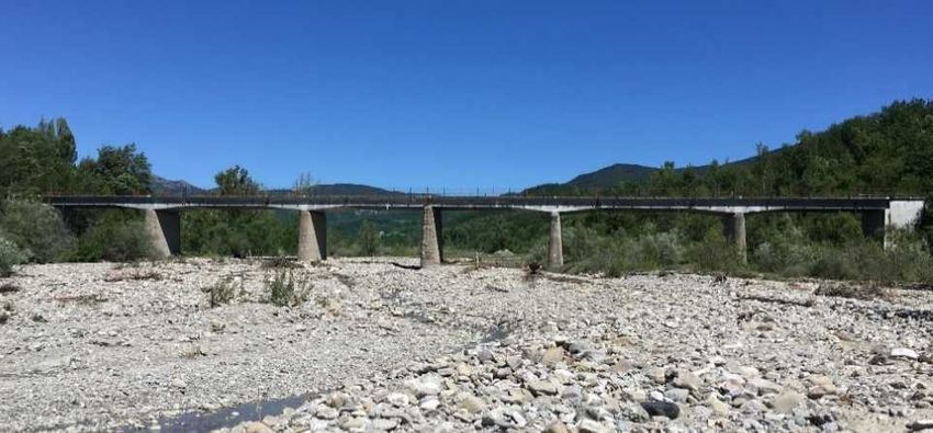
The International Archives of the Photogrammetry, Remote Sensing and Spatial Information Sciences, Volume XLIII-B2-2020, 2020
                                               XXIV ISPRS Congress (2020 edition)

personal experiences - and, above all, they become repeatable.                              3. BACKGROUND
Accordingly, UAS path can be memorized and repeated for
successive inspections, so that data are collected every time from    To conduct a proper bridge inspection by using UAS, it is
the very same positions with respect to the bridge, enhancing         fundamental to know the basic properties of the drone. First, it is
their comparability.                                                  essential to know that an UAS consists of three main
                                                                      components: the aircraft (or Unmanned Aerial Vehicle, UAV), a
                                                                      Ground Control Station (GCS) and a remote control, that allows
           2. BRIDGES INSPECTIONS BY UAS                              the pilot to control the movement of the drone. GCS is a software
                                                                      installed on a PC (or a tablet or a smartphone) that communicates
In recent times, national organizations and universities have         with the aircraft using a wireless telemetry and shows to the
investigated the possibility of using UAS technologies to conduct     remote pilot all the drones-related data (e.g. its position and
bridges visual inspections. These studies or consolidated             performance). Thanks to the GCS and the GPS device, a drone
practices are very heterogeneous and point out the extreme            can fly autonomously following a pre-set path. Modern UAS can
ductility of drones when speaking about road infrastructures          also condensate GCS and remote control into a single device.
inspections.                                                          Multicopters are suitable UAS for infrastructures inspections: the
Speaking about consolidated practices, starting from 2013 RFI, a      helicopter-style structure allows them to fly vertically, to work in
major Italian railway company, has used UAS to conduct                very tight spaces, carrying more than one instrument on their
inspections of specific geometric shapes bridges or bridges that      body, and especially the possibility to conduct stationary flights.
are in morphologically complicated areas (Tisalvi, Vecchi,            This characteristic is essential to take focused images, not
2019). In this way, they can speed inspection procedures by           affected by the movement of the drone. Fixed-wings drones, on
avoiding both the bridge closure to traffic and the use of heavy      the contrary, can be used to conduct an overall inspection of the
equipment (also known as by-bridge equipment). The main               structure and its morphological context, simply by taking nadiral
outcome of their activity is visual data (pictures or videos) that    images. Instead, a crucial aspect of multicopters is the rotation of
allow to enrich the Bridge Management System (BMS). Relying           the camera: the greater the rotation angle, the widest the covered
on these data, RFI has created bridges 3D models and geometric        area into the acquired optical data. This is the reason why many
reliefs. Similar tests have been conducted by several Universities.   drones have a gimbal, a mechanical tool that allows the camera
A possible combination between UAS images and automated               to rotate independently around its axes, not being integral with
algorithm for crack detection (a major cause of RC bridges            the drone’s body. As mentioned in the introductory section, UAS,
deterioration) is proposed by (Yeum, Dyke, 2015). The authors’        and particularly multicopters, can be very useful to conduct
aim is to process the pictures collected by UAS using an              visual inspections and to collect data from a different point of
algorithm that automatically detects cracks on the structure,         view: they can help human beings to reach elements of the bridge
reducing both the time of the data analysis and the outcomes          that are difficult to access, enhancing the safety of the inspection.
subjectivity. The authors developed an object detection               By avoiding the use of by-bridge units, UAS allow not to close
algorithm, whose use represents the most critical phase of the        the structure to traffic, reducing costs, durations and risks of car
entire test. Indeed, each picture differs from the others by its      accidents due to roadway shrinkage. All these aspects, coupled
brightness, scale and background, making the algorithm task very      with the chance to memorize the path of the drone to be used for
complex. To detect possible cracks, the authors applied a sliding     future activities on the same bridge, make UAS powerful
window technique, that uses a fixed rectangular window sliding        instruments to conduct road infrastructures inspections.
on the images to decide whether they contain an object or not.        Before entering in the field tests, it is important to know what
This phase is called by the authors “object detection”, and it is     kind of damages bridges are subjected to. First, bridges exhibit
followed by two other phases: “object grouping” and “crack            different structural defects based on the construction type. One of
damage detection”, that consists in the last step of the proposed     the most common are reinforced concrete (RC) bridges, that are
procedure and allows to decide which detected objects are             made of concrete that is reinforced by steel rebar; steel bridges
cracked and which ones are not. It is evident how this procedure,     are also widespread. The main causes of bridges degradation are
besides making the inspection faster using the drone, also makes      physical, chemical, mechanical and biological processes. Among
the data analysis faster.                                             them, carbonization, chloride pollution, cyclic loads and slow
Another relevant proposal to inspect bridges using UAS comes          phenomena (such as creep and shrinkage) are the most dangerous
from (Omar, Nehdi, 2017). The authors of the study highlight the      and especially affect the structural elements of RC bridges: their
possible combination between UAS and Infrared Thermography,           most common and dangerous consequences are cracking (that
a major NDT technology for bridges inspection. Their main goal        can be divided into spalling and delamination), rebar corrosion
was to detect subsurface delamination in concrete bridge decks        and loss of pre-stressing cables stress. It is now clear why
taking advantage of a particular behaviour of delaminated areas,      periodical inspections and maintenance are essential to prevent
that warm up at a higher rate than the surrounding sound concrete     and avoid the rupture of structural elements and the collapse of
during daytime (vice versa during night-time). In this way, the IR    the bridge.
images are characterized by a series of hotspots where                As a result, road infrastructures managers establish specific
delamination occurs. To acquire appropriate thermal images, it is     inspection and maintenance plans on their structures; these plans
essential to use a high-resolution thermal camera: its spectral       are based on ordinary inspections (that must be done periodically,
range, spatial resolution, frame rate and temperature range are       for example once or twice a year) and furthered inspections (more
crucial parameters. GCP (Ground Control Points) that are visible      sporadic or after specific events that may affect the integrity of
in the infrared spectrum are also essential to distinguish each       the bridge). All these inspections need appropriate equipment that
portion of the bridge deck, as well as RGB images of the same         allows the examination of structural elements by a so-called
portion of the bridge deck, to avoid false positives. Starting from   “contact distance”. All the inspections that do not require the
the thermal images acquired by the drone, the authors utilized a      removal of small structural elements can be carried out by using
k-means clustering technique to identify temperature thresholds,      UAS, which enables the detection of all previous listed damages.
realizing a heat map which different colours indicate different
levels of delamination severity.

                                                This contribution has been peer-reviewed.
                 https://doi.org/10.5194/isprs-archives-XLIII-B2-2020-1145-2020 | © Authors 2020. CC BY 4.0 License.                 1146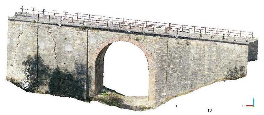
The International Archives of the Photogrammetry, Remote Sensing and Spatial Information Sciences, Volume XLIII-B2-2020, 2020
                                               XXIV ISPRS Congress (2020 edition)

                      4. CASE STUDIES                                   into a global reference system, it is necessary to acquire GPS
                                                                        coordinates of at least three positions around the bridge: to do
In collaboration with Provincia di Piacenza, the administrative         this, a Leica Viva GS 14 GNSS antenna was used.
authority of a northern Italy town, two tests have been carried         The first procedures of the test were the GCPs’ positioning (for a
out, aimed to conduct a visual inspection and a survey of two           total of 24, 12 per each side of the structure) and the identification
bridges near Piacenza. Even though the two bridges are very             of the multistation positions, whose global coordinates had to be
different, the two tests procedures, instruments and outcomes           acquired by using the GNSS antenna. Once the GCPs were fixed
were very similar and will accurately be described in the next          and clearly visible, their local coordinates could be acquired
paragraphs.                                                             using the MS60 measurements. At a later stage, GCPs global
                                                                        coordinates were obtained by a rototraslation with a scale factor.
4.1 Lavaiana Bridge inspection                                          At this point, the UAS survey could begin: a total of five flights
                                                                        were manually carried out, acquiring data from a nadiral position,
The first field test was carried out on June 13th, 2019 during a        on the east and west side of the bridge and flying around two
typical spring-like weather that allowed to take advantage of the       pillars, the second one and the fourth. These last two flights took
sunlight for several hours, for a test total duration of about seven    place in very narrow spaces, so it was decided to conduct them
hours. The surveyed structure (Figure 1) is a 140m x 11m x 8m           manually. All the acquired 4K quality videos lasted between 30
RC bridge that crosses the Lavaiana creek along the SP8 road,           seconds and 5 minutes and were characterized by a 29.7fps
made of six spans, five piers and two abutments.                        frequency. With the MS60, alternately positioned in the pre-set
                                                                        positions, a total of seven scans were acquired, all of them with a
                                                                        5cm x 1cm points network. The first outcome of the field test was
                                                                        the visual inspection of the bridge: typical RC bridges damages
                                                                        were identified, such as spalling phenomena on every pillar, rebar
                                                                        corrosion and moisture spots all over the two abutments. Thanks
                                                                        to the UAS, several structural elements were inspected very
                                                                        quickly and very easily: without having a by-bridge unit or a
                                                                        ladder, bridge bearings conditions were analysed by taking a few
                                                                        seconds video, which can be examined in a later time.
                                                                        Having performed all the listed actions, the field activity ended,
                                                                        and all the acquired data could be processed in laboratory. To this
                                                                        end, a software equipment was used. Agisoft Metashape Pro
                  Figure 1. The Lavaiana Bridge
                                                                        (version 1.5.2 build 7838, Windows 64-bit) (www.Agisoft.com,
                                                                        2019) is a main photogrammetric software allowing several
In the days prior to the survey, a site inspection was conducted:       activities starting from the UAS acquired videos. MatlabTM,
it is extremely important to evaluate the existing situation before     CloudCompare (version 2.10.2, Windows 64-bit) (Girardeau-
the test takes place. During the inspection, it is possible to          Montaut, 2011) and AutoCADTM were also used: their specific
establish which instruments are more suitable for the field test        role and characteristics is discussed in this paragraph. The PC
and if any natural or artificial barrier to the correct execution of    used to carry out all the computations described below was an
the test exists. In this case, the entire structure was surrounded by   Asus X541UV, with an Intel Core i7-6500U CPU, an NVIDIA
a dense vegetation, which represented an obstacle for the drone         GeForce 920MX with 2GB VRAM graphic card and an 8GB
flight: it was then decided to cut the most invasive trees. As said,    RAM. The first laboratory activity was the extraction of the
the test planning was also set up during the inspection: it was         frames from the videos: as a matter of fact, Metashape can only
decided to use a DJI Mavic Pro 2 to acquire visual data of the          build a 3D model starting from pictures, so it allowed to extract
bridge, a Leica Nova Multistation MS60 (MS60) (Fagandini et             single frames with a frequency established by the user. A 29.7fps
al., 2017) equipped with a laser scanner to digitally reconstruct       video lasting 5 minutes was made up by almost 9.000 frames,
the structure with a high level precision and, finally, a Leica Viva    which are clearly too many to be given as an input to the software.
GS 14 GNSS antenna to have georeferenced data. GCPs can also            Therefore, for each uploaded video, a frame step between 5 and
be considered as hardware equipment. They consist in a series of        100 was selected, depending on the drone flying velocity and
enumerated papers, differentiated from each other with a printed        position, corresponding to a frames extraction between 1.2 and
mark which facilitates the identification of each portion of the        0.4fps. The extracted frames were still too many, so a manual
bridge on the acquired visual data.                                     selection of the singles frames was carried out. At the end of this
DJI Mavic Pro is a very flexible drone thanks to its small              procedure, a total of 302 frames were given as an input to
dimensions (about 30cm with open wings) and low weight (less            Metashape, together with the GPS coordinates of the GCPs,
than 1kg), that make it agile but still quite robust. It is equipped    which were obtained through a rototraslation with a scale factor,
with a 20Mpixel Hasselblad camera with a 10bit radiometric              starting from their local coordinates. A further step consisted in
resolution that records 60fps 4K video. Due to the remarkable           the “camera calibration” operation. To do this, the selected
dimensions of the bridge, it was decided to record videos instead       images were uploaded in Matlab, a numerical computing
of taking pictures manually: this way, the pilot just had to control    software, which makes available a proper tool to calibrate the
the UAS position, facilitating the task; a manual flight was            UAS parameters of the camera. At the end of this procedure,
preferred to an autonomous one because of the drone path around         an .xml file was generated: it contained the internal orientation
the structure, which will be discussed below. The MS60 can              parameters (c, ξ0, η0), the focal length (f, mm), the images pixel
measure zenith and nadiral angles with a 1’’ (0.3mgon) accuracy         size (mm) and the geometric distortions of the camera (radial,
and it is equipped with a 3D laser scanner with a scanning speed        tangential, affine and skew, for a total of 7 parameters). The last
of 1.000 points per second and a millimetric accuracy. During the       manual activity was the collimation of the GCPs, which consisted
inspection, three possible station points were identified: by           in detecting them on every single uploaded image and coupling
positioning the MS60 in these positions, a complete 3D model of         them with their correspondent GCP coordinates. The more
the structure can be obtained by merging each single laser              precise this operation, the higher the final model accuracy.
acquisition. Finally, if the outcomes survey have to be included

                                                 This contribution has been peer-reviewed.
                  https://doi.org/10.5194/isprs-archives-XLIII-B2-2020-1145-2020 | © Authors 2020. CC BY 4.0 License.                   1147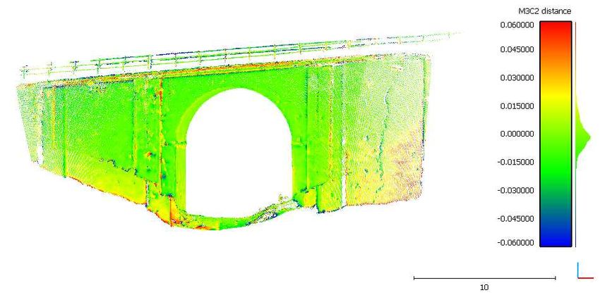
The International Archives of the Photogrammetry, Remote Sensing and Spatial Information Sciences, Volume XLIII-B2-2020, 2020
XXIV ISPRS Congress (2020 edition)
The successive step was the creation of the sparse cloud. It was
automatically computed by Metashape through an operation
called Photo alignment, and the only user’s task was to select the 0.03
output quality on a five levels scale (from “lowest” to
“ultrahigh”): in this case, the sparse cloud was computed
selecting a “medium” quality. The output was computed in about 0.00
30 minutes and it was made of 66.011 points. Based on the sparse
cloud quality and before computing the dense cloud, namely the
final 3D model, it was possible to improve the total accuracy by
-0.03
using the “Optimize camera alignment” tool, which allowed to
correct possible estimation errors of the parameters, leading to
35
deformations in the final model. Finally, choosing once again a Figure 3. CloudCompare's output (M3C2)
“medium” quality, the dense cloud could be computed through a
Metashape command called “Build dense cloud” based on a
computation of the collinearity equations system. With a
computational time of about five hours, the final output was a
6.042.252 points dense cloud (Figure 2) with an 9mm accuracy;
the “medium” quality represents a compromise between a good
quality of the model and a reasonable time of computation
(Gagliolo et al., 2018; Pagliari, Pinto, 2018).
Figure 4. Points' numerosity
Figure 2. Dense cloud of the Lavaiana bridge
Considering that the MS60 model precision is greater than the
photogrammetric one, these differences can be especially
It was possible to verify the consistency of the survey by ascribed to three factors: the presence of outliers (or “noisy”
comparing the two clouds of points obtained using the two points) that were not removed correctly from the sparse cloud;
methods (the photogrammetric and the laser ones). To do this, the the greater difficulty of reconstruct sharp edges through
M3C2 (Lague et al., 2013) tool of CloudCompare was used to photogrammetry; or an intrinsic error of the model. As said
calculate the metric distance between groups of points of each before, MetaShape’s dense cloud is characterized by a 9mm
cloud. As inputs, the tool requires a “reference cloud” (the most accuracy: this means that each point of the 3D model can differ
precise one, generally) and a “compared” one, a “sampling rate” from the real structure by no more than 2.7cm (with a 99.7%
(m) and three additional parameters (“normal”, “projection”, probability).
“max depth”). The laser scanner cloud and the photogrammetric
one were respectively selected as “reference” and “compared
cloud”; the sampling procedure allowed to reduce the high
numerosity of the reference cloud, making the software
computation easier. A 0.025m sampling rate was selected: the
higher this parameter, the less numerous the output’s cloud. A
0.025m sampling rate meant that the new reference cloud could
be made by taking one point every 25mm from the original cloud.
The subsampled reference cloud was made by about one million
points, around 1/6 of the original cloud: they are called “core
points” and represent the reference points to calculate the
distance between the two models. The “normal” and “projection”
parameters generate a sort of cylinder around each core point;
their best fit values are generally recommended by the software
itself. The last parameter is called “max depth” and establishes
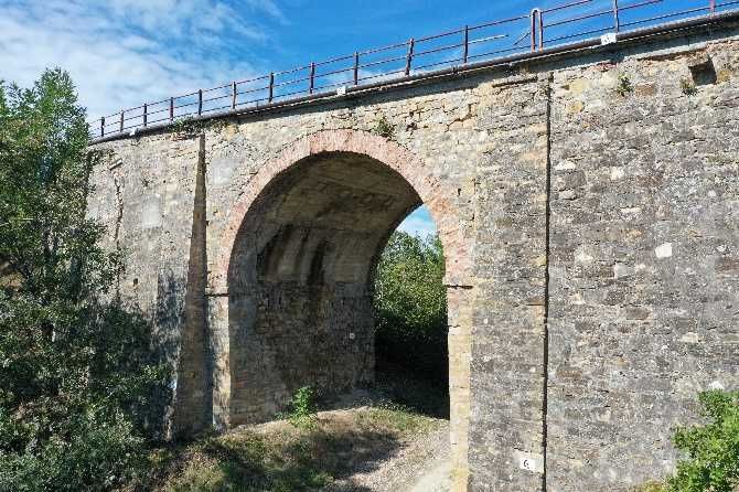
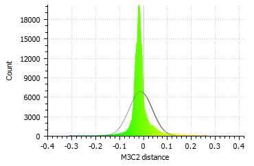
the maximum searching distance. As outcomes of this Figure 5. Points' distribution around the average value
comparison, CloudCompare generated an overall image of the
bridge and two histograms: each of them confirmed the good Therefore, portions of bridge with a distance lower than this can
quality of the photogrammetric cloud. In particular, as can be be considered satisfying; on the contrary, portions characterized
seen in Figure 3 and in Figure 4, along most of the structure, the by a distance greater than 2.6cm from the MS model represent
distance between the two clouds is less than 7mm (light green points that do not belong to the structure or structural elements
and yellow colours); the major distances, that are around 3cm and that were not correctly reconstructed. Figure 5 represents the
highlighted in blue and red, are less numerous and appear along Gaussian statistical distribution of the point, centered around its
the bridge’s abutments, central pillars and intrados external average value (μ = 0,010m) and with a standard deviation σ =
portions. 0.051m.
This contribution has been peer-reviewed.
https://doi.org/10.5194/isprs-archives-XLIII-B2-2020-1145-2020 | © Authors 2020. CC BY 4.0 License. 1148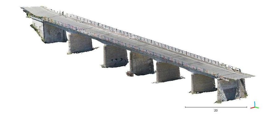
The International Archives of the Photogrammetry, Remote Sensing and Spatial Information Sciences, Volume XLIII-B2-2020, 2020
XXIV ISPRS Congress (2020 edition)
After these evaluations on the outputs, if the photogrammetric
model accuracy is confirmed, the photogrammetric dense cloud
can be used as a base of successive operations. As an example, it
is possible to use some Metashape proper tools to calculate the
extension of spots of humidity in terms of area (m2) and perimeter
(m). By exporting the 3D model in AutoCADTM, this design
software was used to draw the bridge’s plant, sections and
prospects and to metrically measure them.
4.2 Lanzone Bridge inspection
Figure 7. Dense cloud of the Lanzone bridge
The second test was conducted on September 24th, 2019 during a
sunny day, a perfect weather condition for a drone survey. The As shown by Figure 8, the distance between the majority of the
surveyed structure (Figure 6) is a 30m x 9.5m x 8m one arch points of the model is less than 1cm (light green and yellow
masonry bridge called Lanzone Bridge located in Dignini, a small points). Red and blue points, which represent distances around
town in the Vernasca municipality (Piacenza -Italy). 3cm, are less than the Lavaiana case and distributed along the
upper portion of the structure, characterized by sharp edges.
0.03
0.00
-0.03
10
Figure 8. CloudCompare’s output
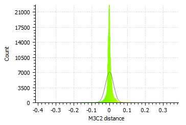
Figure 6. The Lanzone Bridge Figure 9 represents the statistical distribution of the points, again
following a Gaussian curve centered around its average value (μ
Both the equipment and the procedures were the same as the = 0,000m) and with a standard deviation σ = 0.023m.
survey for the Lavaiana bridge, except for the fact that this time,
because of the small dimension of the bridge, visual data were
acquired by taking pictures instead of recording videos. This
choice was made during an inspection conducted a couple of
months before the survey, during which it was decided to remove
some dense vegetation very close to the structure. Besides being
a physical obstacle for the flight of the drone, it did not allow to
properly reconstruct the covered portions of the bridge. Again,
thanks to the size of the bridge, the MS60 computed the 3D
model of the bridge by scanning only its east and west side, for a
total of two clouds to be merged instead of the seven computed
for the Lavaiana bridge. A total of 12 GCPs were positioned on
the structure, five on each side and two on the internal walls of
the masonry arch. A total of four drone flights were performed,
during which 146 pictures were taken. The visual inspection of
the bridge highlighted several structural damages, such as deep Figure 9. Points' distribution around the average value
and extended cracks, humidity spots and vegetation grown
between the walls stones. As before, once the validity of the photogrammetric model was
The laboratory test followed the very same procedure of the first confirmed, the dense cloud could be used as the basis for the
one, apart from extraction phase of the frame. All the 146 pictures realization of plants, prospects and section by using AutoCADTM.
were given as input to Metashape, which computed a “medium”
quality sparse cloud made of 108.904 points with a 20 minutes 5. CONCLUSIONS
computational time by using the same PC as before. The dense
cloud was computed in about five hours and was made of Many road bridges were built right after the World War II, so
5.912.527 points, with a 7mm accuracy (Figure 7). they are heading to the end of their life cycle. Therefore, to safely
Again, the validity of the outcome was double checked with the perform their function, they must undergo maintenance
laser scanner cloud using the same tool and parameters of the first interventions, which can be substantial. All these interventions
case study. The outcomes of the analysis were the same as before, are necessarily preceded by inspection and monitoring activities,
including the evaluations made on them. to determine the structural conditions of the bridge and their
evolution over time. As a contribution to the accomplishment of
the above activities, UAS is the most suitable instrument: by
using this modern technology, visual inspections can be more
This contribution has been peer-reviewed.
https://doi.org/10.5194/isprs-archives-XLIII-B2-2020-1145-2020 | © Authors 2020. CC BY 4.0 License. 1149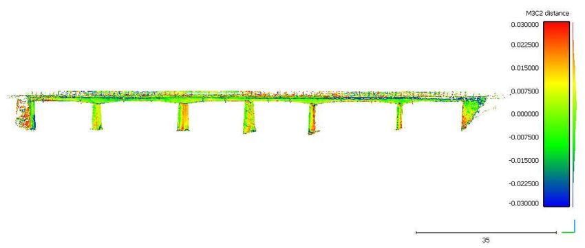
The International Archives of the Photogrammetry, Remote Sensing and Spatial Information Sciences, Volume XLIII-B2-2020, 2020
                                                 XXIV ISPRS Congress (2020 edition)

frequent, well-timed and safer for the workers, who may                Chaize, P., Dagbert, M., 2019. Sécurité des ponts: éviter un
currently operate in unstable circumstances. Objective and             drame. Rapport d'information. Accessed April 06, 2020.
repeatable inspections are further advantages of drones: a bridge      https://www.senat.fr/rap/r18-609/r18-6091.pdf
that undergoes monitoring activities can be inspected on a
quarterly or annual basis by acquiring data from the very same         Fagandini, R., Federici, B., Ferrando, I., Gagliolo, S., Pagliari,
perspective, distance and angles, making them as objective as          D., Passoni, D., Pinto, L., Rossi, L., Sguerso, D. 2017. Evaluation
possible. On this, many proposals are already in place for bridges     of the Laser Response of Leica Nova MultiStation MS60 for 3D
inspection, such as those from Intel and Flyability (Jordan et al.     Modelling and Structural Monitoring. In International
2018). Table 1 sums up the different UAS applications in terms         Conference on Computational Science and Its Applications;
of bridges inspection (destructive and NDT) and monitoring             Springer: Berlin, Germany, 2017. pp. 93–104.
activities.
                                                                       Gagliolo, S., Fagandini, R., Federici, B., Ferrando, I., Passoni,
                               UAS - Multicopter                       D., Pagliari, D., Pinto, L., Sguerso, D. 2018. Parameter
                                                                       optimization for creating reliable photogrammetric models in
 Inspection                                                            emergency scenarios. Applied Geomatics, 10(4), 501-514.
                      Properties           Payload       Sensor
    type
                 Stability; wide                                       Girardeau-Montaut, D. 2011. Cloudcompare-open source
Preliminary activity’s range to have      Limited        GSD <         project. OpenSource Project. Accessed April 06, 2020.
survey       an overall site’s sight;     (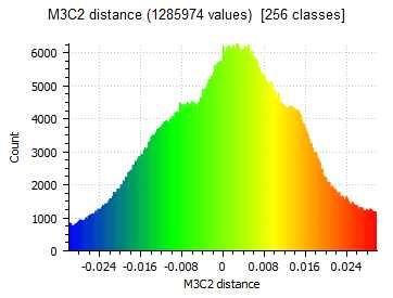
You can also read