LOWER EXTREMITY SAGITTAL PLANE JOINT ANGLES - VALIDATION OF FIGUR8 SENSOR NETWORK
←
→
Page content transcription
If your browser does not render page correctly, please read the page content below
SEPTEMBER 27, 2019

VALIDATION OF FIGUR8 SENSOR NETWORK
LOWER EXTREMITY SAGITTAL PLANE JOINT ANGLES

Alexia Stylianou, MS   Shannon Linderman, MS, MA   Hannah Stein, BS   Weiran Song, BS

Donna Moxley Scarborough, PHD, MS, PT
Copyright © 2019 FIGUR8, Inc. All rights reserved.
The information contained in this document is the proprietary and exclusive property of FIGUR8, inc. Except as otherwise indicated.
No part of this document, in whole or in part, may be reproduced, stored, transmitted, or used for design purposes without the prior
written permission of FIGUR8.

The information in this document is provided for informational purposes only. FIGUR8 expressly disclaims all warranties, express or
implied, including without limitation those of merchantability, fitness for a particular purpose and noninfringement.
Table of Contents

Introduction .............................................................................................................................................. 2

Purpose ..................................................................................................................................................... 2

Methods .................................................................................................................................................... 3

Participants .............................................................................................................................................. 3

Equipment Set-up .................................................................................................................................... 3

Data Collection Activity .......................................................................................................................... 3

Data Processing ....................................................................................................................................... 4

Data Analysis............................................................................................................................................ 4

Results ....................................................................................................................................................... 5

Conclusion ................................................................................................................................................ 7

References ................................................................................................................................................ 7

                                                          Validation of FIGUR8 Sensor Network Lower Extremity Sagittal Plane Joint Angles
                                                                                                                                  Page 01
Introduction The FIGUR8 movement platform can determine joint angles using the inertia measuring unit (IMU) part of the sensor system. The IMU sensor network can facilitate the calculation of joint angles in the sagittal plane using gyroscope position data from two sensors placed above and below a specific joint. There are multiple types of other kinematic measurement systems for joint angles including high-speed 3D motion capture cameras, marker-less optical tracking, and other wearable IMU-based systems with different trade-offs associated with each methodology. Three-dimensional optical motion capture camera systems are the current gold standard for joint angle measurements in biomechanics research. One of the primary motion capture systems reports accuracy of less than 2° of error compared to clinical goniometer measurements (Vicon Motion Systems Ltd UK). These motion capture systems have high-speed cameras that triangulate the position of markers affixed to a subject’s body in 3D space in order to calculate joint angles. Wearable IMUs have gained popularity for joint angle measurement. Their creators face the challenge of determining joint calculations using less anatomical reference points than motion capture systems. Therefore, wearable motion analysis systems have compared joint angle calculations to those collected simultaneously from a motion capture system, in order to provide a benchmark of the validity of FIGUR8 angle calculations. Purpose This study evaluated the validity of FIGUR8 sensor network assessment of lower extremity joint angles compared to an optical motion capture system during a common dynamic activity, a bilateral deep squat. Validation of FIGUR8 Sensor Network Lower Extremity Sagittal Plane Joint Angles Page 02
Methods
Participants
A total of 10 subjects, 4 females and 6 males (mean age = 25.8 ± 2.95 years), were recruited
for this study. Each subject completed 3 trials of a bilateral deep squat task with simultaneous
joint angle recording using the FIGUR8 sensor network and the VICON MX T-series 3D motion
capture system.
Equipment Set-up
An IMU sensor network was established by applying FIGUR8 sensors to the following locations on
each subject: lateral thigh, lateral shank, and above the pelvis. The FIGUR8 IMU sensor network
records data using an iOS app at 50hz streamed via Bluetooth Low Energy to a mobile device.
The VICON system required a set of reflective markers (total of 62) placed on each subject’s
body on designated anatomical landmarks to allow identification of joint centers and body
segments. A well-established marker set was affixed directly to the skin using double-sided
hypoallergenic tape. A series of 16 Vicon MX™ T-series cameras recording at 100 Hz (Vicon
Motion Systems Ltd, Oxford, Oxfordshire, UK) were used to capture marker (14 mm) position
data in 3D space. The VICON system was calibrated prior to each subject’s testing session
following standard protocol established by the company. The motion capture lab coordinate
system was designed with the X axis in line with forward translation of the knee during the
squat (sagittal plane), the Z axis as the vertical direction (transverse plane) and the Y axis was
determined as the cross-product of the Z and X axes (frontal plane).
Data Collection Activity
The simultaneous data collection started with an anatomical calibration trial. Each subject
was positioned in a standing position with the feet shoulder-width apart with the toes aligned,
facing straight ahead and shoulders at 90 degrees abduction and elbows at 90 degrees
flexion. The subject was then instructed to perform a bilateral deep squat and maintain the
same foot placement. Subjects descended into the squat and subjects then returned to their
starting position at their own pace. Subjects performed 3 trials of the bilateral deep squat.
The most representative trial of each subject’s squat motion was selected for analyses. The
bilateral deep squat was chosen as the data collection activity because it is well suited to
sagittal plane study and does not limit the range of motion of the hip and knee joints.
Validation of FIGUR8 Sensor Network Lower Extremity Sagittal Plane Joint Angles
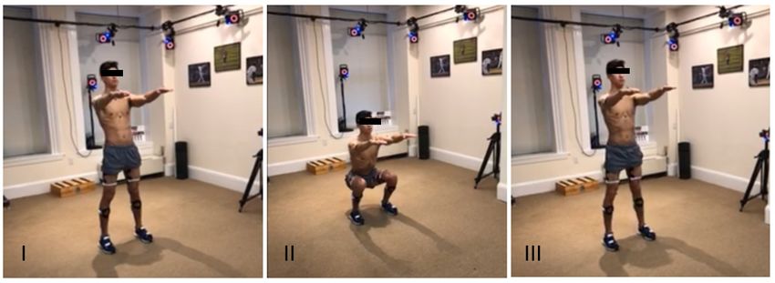
Page 03Figure 1. View of start (I) mid-point (II) and return to start (III) of the bilateral deep squat activity Data Processing No signal processing or filtering was applied to the FIGUR8 sensor network angle data. Vicon marker position data were processed with a low-pass fourth-order zero-lag Butterworth filter with a cut-off frequency of 18 Hz. Data Analysis Sagittal plane joint angle data for the right knee and right hip was extracted from both the Vicon and FIGUR8 systems. Knee angles from the FIGUR8 IMU sensor network was calculated based on gyroscope data from sensors placed above and below the knee joint on the quadriceps and gastrocnemius respectively. Hip angles were calculated from gyroscope data from a FIGUR8 sensor above the hip on the pelvis and the same sensor placed on the quadriceps. Joint angle calculations for the inertial measurement unit data were performed in the FIGUR8 Motion Modeler web-based software platform. Vicon data analysis was performed using the biomechanics software Visual 3D™ (Version 5, C-Motion Research Biomechanics, Inc., Germantown, MD, USA). All joint angle calculations were performed using a 15-segment, 6 degree-of-freedom (DoF) full-body skeletal model derived from marker position data. The knee joint center was defined as the center of a ray passing through markers placed on the medial and lateral femoral condyles. The hip joint center was defined based on the ASIS (anterior superior iliac spine) and PSIS (posterior superior iliac spine) landmarks as part of the CODA pelvis model. The hip and knee sagittal plane angles for the entire bilateral deep squat motion sequence calculated using both systems were plotted with respect to time. An error curve calculating the difference between the two systems at each time point was also plotted on the same time scale (Figure 2). Paired 2-way T-Tests were performed to compare the peak hip and knee flexion angles between the two measurement systems. The level of statistical significance was established at p
FIGUR8
                                                                                                                       VICON
                                                                                                                       ERROR
 ANGLE (DEGREES)

Figure 6. A timestamp adjusted example of a knee joint angle in the sagittal plane during a bilateral deep squat as measured by a
FIGUR8 sensor network (blue) and a VICON optical motion capture system (orange). The error between the two systems is plotted in
red. The peak angle was computed and compared for each trial using both systems.

Results

No statistically significant difference in peak knee (p = 0.26) or hip (p = 0.73) flexion angle was
observed between the FIGUR8 and VICON systems (Table 1).

              Table I Comparison of peak knee and hip joint flexion angles during the bilateral deep squat activity.

            Measurement System                              Peak Knee Flexion             Peak Hip Flexion
            FIGUR8                                          111.60 ± 14.07°               95.27 ± 10.42°
            VICON                                           109.97 ± 14.64°               93.59 ± 17.61°
            P value (significance set at < 0.05)            p = 0.26                      p = 0.73

The average absolute difference in knee joint sagittal plane angle for the entire bilateral deep
squat motion sequence between the two systems was 4.37° ± 2.92 across all subjects with the
average absolute difference by subject displayed in Figure 3. Average absolute difference in
measurements between the two systems for the entire motion sequence was 6.49° ± 5.66 for
hip angle in the sagittal plane (Figure 4).

                                                   Validation of FIGUR8 Sensor Network Lower Extremity Sagittal Plane Joint Angles
                                                                                                                          Page 05
ERROR (DEGREES)
Figure 3. Average absolute difference between FIGUR8 and VICON knee angles for the entire squat motion sequence
for each subject.
ERROR (DEGREES)
Figure 4. Average absolute difference between FIGUR8 and VICON hip angles across the entire squat motion se-
quence for each subject.
Validation of FIGUR8 Sensor Network Lower Extremity Sagittal Plane Joint Angles
Page 06Conclusion
There was no significant difference in peak knee or hip sagittal angle measurements between
the FIGUR8 and VICON systems. For all trials, the average difference in the angle values re-
ported by FIGUR8 and VICON systems remained below 7° for the knee and below 11° for the
hip. Study findings reveal good agreement between lower extremity sagittal plane measure-
ments between the FIGUR8 and VICON systems at the point of peak flexion (ie. the deepest
part of the squat). Study findings are also consistent with other IMU sensor based squat anal-
yses that report standard error of measurement for knee and hip joint angles in the sagittal
plane of around 5 degrees between an IMU sensor network and a VICON system.1 Similar to
our study findings, the greatest error between the two systems was at the time of maximum
hip angle calculation with differences greater than 5 degrees.1 However, the discrepancy of
maximum hip angle calculations between the FIGUR8 and VICON systems in this study offers
significant improvement over other mobile device angle measurement systems that report
differences of more than 40 degrees in hip flexion versus the VICON system during squatting.2
References
1) Mohammad AA, Nicholas K, Button K, Sparkes V, Sheeran S, Davies JL. Inertial Measure-
ment Units for Clinical Movement Analysis: Reliability and Concurrent Validity. Sensors (Basel).
2018 Feb 28;18(3). pii: E719. doi: 10.3390/s18030719.
2) Krause, D.A.; Boyd, M.S.; Hager, A.N.; Smoyer, E.C.; Thompson, A.T.; Hollman, J.H. Reliability
and accuracy of a goniometer mobile device application for video measurement of the func-
tional movement screen deep squat test. Int. J. Sports Phys. Ther. 2015, 10, 37–44.
Validation of FIGUR8 Sensor Network Lower Extremity Sagittal Plane Joint Angles
Page 07COPYRIGHT © 2019 FIGUR8, INC. ALL RIGHTS RESERVED.
You can also read