Manual PN/CAN Gateway, PROFINET/CANopen Slave - Helmholz
←
→
Page content transcription
If your browser does not render page correctly, please read the page content below
PN/CAN Gateway, PROFINET/CANopen Slave
Manual
Version 2 | 1/26/2021 | for firmware V1.00 and above

                                                                                      Link to newest version of
                                                                                      manual

Helmholz GmbH & Co. KG | Hannberger Weg 2 | D-91091 Großenseebach | Germany
Phone +49 9135 7380-0 | Fax +49 9135 7380-110 | info@helmholz.de | www.helmholz.com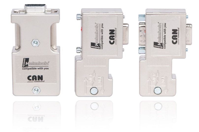
Notes

All rights reserved, including those related to the translation, reprinting, and reproduction of this
manual or of parts thereof.

No part of this manual may be reproduced, processed, duplicated, or distributed in any form
(photocopy, microfilm, or any other methods), even for training purposes or with the use of
electronic systems, without written approval from Helmholz GmbH & Co. KG.

All rights reserved in the event of the granting of a patent or the registration of a utility model.

To download the latest version of this manual, please visit our website at www.helmholz.de.

We welcome all ideas and suggestions.

Copyright © 2021 by

Helmholz GmbH & Co. KG

Hannberger Weg 2 | 91091 Großenseebach

Revision Record:

 Version   Date         Change

    1      12/4/2020    First version

    2      1/26/2021    Corrections of content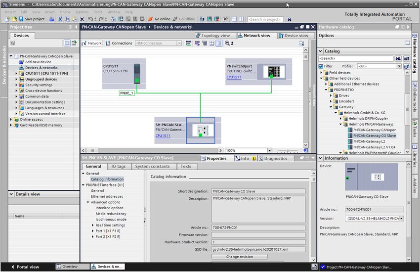
Contents
1     General ............................................................................................................. 5
    1.1       Target audience for this manual............................................................................................... 5

    1.2       Safety instructions ................................................................................................................... 5

    1.3       Note symbols and signal words ............................................................................................... 6

    1.4       Intended use ........................................................................................................................... 7

    1.5       Improper use ........................................................................................................................... 7

    1.6       Liability .................................................................................................................................... 8

      1.6.1      Disclaimer of liability ............................................................................................................ 8

      1.6.2      Warranty.............................................................................................................................. 8

    1.7       Recycling / WEEE ..................................................................................................................... 9

2     System overview ............................................................................................. 10
    2.1       General/area of application ................................................................................................... 10

    2.2       Properties of PN/CAN-Gateways CANopen ............................................................................ 10

3     Installation ..................................................................................................... 11
    3.1       Access restriction ................................................................................................................... 11

    3.2       Electrical installation .............................................................................................................. 11

    3.3       Protection against electrostatic discharges ............................................................................. 11

    3.4       Overcurrent protection .......................................................................................................... 11

      3.4.1      Operation .......................................................................................................................... 11

    3.5       Installation position ............................................................................................................... 12

    3.6       Minimum clearance ............................................................................................................... 12

4     Setup and wiring ............................................................................................ 13
    4.1       EMC/safety/shielding ............................................................................................................. 13

    4.2       Wiring of the PN/CAN Gateway ............................................................................................. 14

      4.2.1      Voltage supply ................................................................................................................... 14

      4.2.2      CAN bus connection .......................................................................................................... 14

      4.2.3      PROFINET connection ........................................................................................................ 14

      4.2.4      USB interface ..................................................................................................................... 14

5     CAN bus .......................................................................................................... 15
    5.1       Wiring a CAN Bus .................................................................................................................. 15

    5.2       CAN bus plug ........................................................................................................................ 15

    5.3       The CANopen protocol .......................................................................................................... 16

      5.3.1      CANopen objects ............................................................................................................... 16

PN/CAN Gateway, PROFINET/CANopen Slave | Version 2 | 1/26/2021                                                                                         3
5.3.2      CANopen functions ........................................................................................................... 17

      5.3.3      Network management ....................................................................................................... 18

6     Setup and use ................................................................................................. 20
    6.1       Transfer EDS or DCF file to PN/CAN Gateway......................................................................... 20

    6.2       Configure Gateway................................................................................................................ 22

      6.2.1      Install GSDML file .............................................................................................................. 22

      6.2.2      Parameterization ................................................................................................................ 23

      6.2.3      Configuration .................................................................................................................... 24

      6.2.4      Maximum extension of a PN/CAN Gateway configuration.................................................. 25

    6.3       Assign the PROFINET device-name ......................................................................................... 26

7     Programming in the PLC ................................................................................ 27
    7.1       Control .................................................................................................................................. 27

    7.2       Status .................................................................................................................................... 28

    7.3       Read/write random SDO........................................................................................................ 30

      7.3.1      Transfer of SDO data > 4 Byte ............................................................................................ 31

    7.4       Transmitting Emergency Messages ........................................................................................ 32

      7.4.1      Internal Emergency messages of PN/CAN Gateway ............................................................ 33

    7.5       PROFINET Diagnostic messages ............................................................................................. 34

8     Internal SDO ................................................................................................... 35
    8.1       Start-up behavior SDO 2FFF ................................................................................................... 35

    8.2       Status SDO 2FFE .................................................................................................................... 35

    8.3       Error register SDO 1001 ......................................................................................................... 35

    8.4       Error memory SDO 1003 ....................................................................................................... 35

    8.5       Node-ID SDO 100B ................................................................................................................ 35

9     LED-based diagnosis ....................................................................................... 36
10        Technical data.............................................................................................. 37

PN/CAN Gateway, PROFINET/CANopen Slave | Version 2 | 1/26/2021                                                                                       4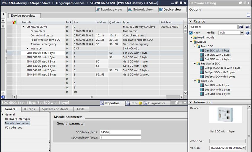
1      General
This operating manual applies only to devices, assemblies, software, and services of Helmholz GmbH
& Co. KG.

1.1 Target audience for this manual
This description is only intended for trained personnel qualified in control and automation
engineering who are familiar with the applicable national standards. For installation, commissioning,
and operation of the components, compliance with the instructions and explanations in this
operating manual is essential.

Configuration, execution, and operating errors can interfere with the proper operation of the PN/CAN
Gateways and result in personal injury, as well as material or environmental damage. Only suitably
qualified personnel may operate the devices!

Qualified personnel must ensure that the application and use of the products described meet all the
safety requirements, including all relevant laws, regulations, provisions, and standards.

1.2 Safety instructions
The safety instructions must be observed in order to prevent harm to living creatures, material goods,
and the environment. The safety notes indicate possible hazards and provide information about how
hazardous situations can be prevented.

PN/CAN Gateway, PROFINET/CANopen Slave | Version 2 | 1/26/2021                                       5
1.3 Note symbols and signal words

If the hazard warning is ignored, there is an imminent danger to life and health of people from electrical
voltage.

If the warning is ignored, there is a probable danger to life and health of people.

If the caution note is ignored, people can be injured or harmed.

Draws attention to sources of error that can damage equipment or the environment.

Gives an indication for better understanding or preventing errors.

PN/CAN Gateway, PROFINET/CANopen Slave | Version 2 | 1/26/2021                                         6
1.4 Intended use
The "PN/CAN Gateway CANopen Slave" enables the connection of a PROFINET network with a
CANopen network. The PN/CAN Gateway is a CANopen slave according to .CiA standard DSP301
V4.2.

All components are supplied with a factory hardware and software configuration. The user must carry
out the hardware and software configuration for the conditions of use. Modifications to hardware or
software configurations which are beyond the documented options are not permitted and nullify the
liability of Helmholz GmbH & Co. KG.

The PN/CAN Gateway may not be used as the only means for preventing hazardous situations on
machinery and systems.

Problem-free and safe operation of the PN/CAN Gateway presumes proper transport, storage, setup,
assembly, installation, commissioning, operation, and maintenance.

The ambient conditions provided in the technical specifications must be adhered to.

The PN/CAN Gateway has a protection rating of IP20 and must be installed in an electrical operating
room or a control box/cabinet in order to protect it against environmental influences. To prevent
unauthorized access, the doors of control boxes/cabinets must be closed and possibly locked during
operation.

1.5 Improper use

The consequences of improper use may include personal injuries of the user or third parties as well as
property damage to the control system, the product, or the environment. Use the PN/CAN Gateway only
as intended!

PN/CAN Gateway, PROFINET/CANopen Slave | Version 2 | 1/26/2021                                       7
1.6 Liability
The contents of this manual are subject to technical changes resulting from the continuous
development of products of Helmholz GmbH & Co. KG. In the event that this manual contains
technical or clerical errors, we reserve the right to make changes at any time without notice.

No claims for modification of delivered products can be asserted based on the information,
illustrations, and descriptions in this documentation. Beyond the instructions contained in the
operating manual, the applicable national and international standards and regulations must also be
observed in any case.

1.6.1 Disclaimer of liability
Helmholz GmbH &Co. KG is not liable for damages if these were caused by use or application of
products that was improper or not as intended.

Helmholz GmbH & Co. KG assumes no responsibility for any printing errors or other inaccuracies
that may appear in the operating manual unless there are serious errors about which Helmholz GmbH
& Co. KG was already demonstrably aware.

Beyond the instructions contained in the operating manual, the applicable national and
international standards and regulations must also be observed in any case.

Helmholz GmbH & CO. KG is not liable for damage caused by software that is running on the user’s
equipment which compromises, damages, or infects additional equipment or processes through the
remote maintenance connection and which triggers or permits unwanted data transfer.

1.6.2 Warranty
Report any defects to the manufacturer immediately after discovery of the defect.

The warranty is not valid in case of:

  • Failure to observe these operating instructions

  • Use of the device that is not as intended

  • Improper work on and with the device

  • Operating errors

  • Unauthorized modifications to the device

The agreements met upon contract conclusion under “General Terms and Conditions of Helmholz
GmbH & Co. KG” apply.

PN/CAN Gateway, PROFINET/CANopen Slave | Version 2 | 1/26/2021                                   8
1.7 Recycling / WEEE
The company Helmholz GmbH & Co. KG is registered as a manufacturer with the HELMHOLZ brand
and the device type "Small devices of information and telecommunications technology for exclusive
use in households other than private households" as well as the following registration data:

Helmholz GmbH & Co. KG,
Location / Headquarters: 91091 Großenseebach,
Address: Hannberger Weg 2,
Name of authorized representative: Carsten Bokholt,

Registration number: DE 44315750.

The electrical devices described in this document are to be recycled. According to Directive 2012/19 /
EU on waste electrical and electronic equipment (WEEE), they must not be disposed of by municipal
waste disposal companies.

PN/CAN Gateway, PROFINET/CANopen Slave | Version 2 | 1/26/2021                                     9
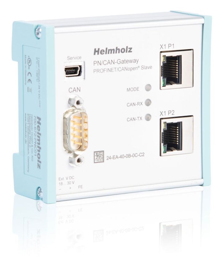
2       System overview

2.1 General/area of application
The "PN/CAN Gateway, PROFINET/CANopen Slave" enables the coupling of machines with CANopen
bus to machines with PROFINET network. The PN/CAN Gateway represents a freely configurable,
fully-fledged CANopen device on the CAN bus and extended the PLC – system / machine to a
CANopen device.

On the PROFINET network, the PN/CAN Gateway is a PROFINET I/O device. The data of the CANopen
SDOs are transparently and freely configurable inserted into the PROFINET network and can thus be
read or written directly in the PLC.

The PN/CAN Gateway is integrated into the hardware configurator of the PROFINET controller with a
GSDML file, and all values of the PN/CAN-Gateways are available as IO information. Special handling
blocks are not necessary. An EDS or DCF file is used to permanently load a manufacturer-specific
CANopen device configuration into the device.

2.2 Properties of PN/CAN-Gateways CANopen
The PN/CAN Gateway, PROFINET/CANopen Master has the following properties:

  • PROFINET IO device as defined in IEC 61158-6-10

  • Integrated two-port Ethernet switch

  • Full-duplex transmission rate of 100 Mbps

  • PROFINET Conformance Class C

  • Media redundancy (MRP client)

  • CANopen device as of CANopen protocol DSP 301

  • Up to 1 Mbps CAN bit rate

  • Up to 16 TPDOs / 16 RPDOs

  • Up to 1440 bytes input and 1440 bytes output data on PROFINET

  • Supports NMT, Heartbeat, node guarding, Sync and emergency messages

  • Configuration using GSDML file

  • No handling blocks necessary

    • 24 V DC power supply

    • 3 LEDs, bi-color

    • USB device interface to load the configuration and for online diagnosis and firmware update

PN/CAN Gateway, PROFINET/CANopen Slave | Version 2 | 1/26/2021                                      10
3 Installation
3.1 Access restriction
The modules are open operating equipment and must only be installed in electrical equipment
rooms, cabinets, or housings.
Access to the electrical equipment rooms, cabinets, or housings must only be possible using a tool or
key, and access should only be granted to trained or authorized personnel.
3.2 Electrical installation
Observe the regional safety regulations.
3.3 Protection against electrostatic discharges
To prevent damage through electrostatic discharges, the following safety measures are to be followed
during assembly and service work:
• Never place components and modules directly on plastic items (such as polystyrene, PE film) or in
their vicinity.
• Before starting work, touch the grounded housing to discharge static electricity.
• Only work with discharged tools.
• Do not touch components and assemblies on contacts.
3.4 Overcurrent protection
Overcurrent protection is not necessary as the PN/CAN Gateway transports no load current. The
power supply of the PN/CAN Gateway electronics is to be secured externally with a fuse of maximum
1 A (slow-blowing).
3.4.1 Operation
Operate the PN/CAN Gateway only in flawless condition. The permissible operating conditions and
performance limits must be adhered to.
Retrofits, changes, or modifications to the device are strictly forbidden.
The PN/CAN Gateway is a piece of operating equipment intended for use in industrial plants. During
operation, all covers on the unit and the installation must be closed in order to ensure protection
against contact.
Bus connections are interrupted when the PN/CAN Gateway is switched off!
Before commencing with any kind of work on the PN/CAN Gateway, ensure that no unpermitted
disruptions of connected systems occur following interruption of the bus connections.
PN/CAN Gateway, PROFINET/CANopen Slave | Version 2 | 1/26/2021 11Installation must be carried out according to VDE 0100/IEC 364 and performed in accordance with
applicable national standards. The PN/CAN Gateway has protection rating IP20. If a higher protection
rating is required, the system must be installed in a housing or control cabinet. In order to ensure safe
operation, the ambient temperature must not exceed 60°C.
3.5 Installation position
The PN/CAN Gateway can be installed in any position. The front plate must be accessible in order to
plug in bus lines.
3.6 Minimum clearance
It is recommended to adhere to the minimum clearances specified when installing devices. Adhering
to these minimum clearances will ensure that:
• The modules can be installed and removed without having to remove any other system
components
• There will be enough space to make connections to all existing terminals and contacts using
standard accessories
• There will be enough space for cable management systems (if needed)
PN/CAN Gateway, PROFINET/CANopen Slave | Version 2 | 1/26/2021 124 Setup and wiring
4.1 EMC/safety/shielding
The PN/CAN Gateway complies with EU Directive 2004/108/EC (“Electromagnetic Compatibility”).
One effective way to protect against disturbances caused by electromagnetic interference is to shield
electric cables, wires, and components.
When setting up the system and routing the required cables, make sure to fully comply with all
standards, regulations, and rules regarding shielding. Precisely observe the corresponding texts of the
PROFIBUS user organization for setting up PROFINET and the setup guidelines of CANopen. All work
must be done professionally!
Shielding faults can result in serious malfunctions, including the system’s failure.
To ensure electromagnetic compatibility (EMC) in your control cabinets in electrically harsh
environments, the following EMC rules are to be observed in the design:
• All metal parts of the cabinet are to be connected with each other over a large area with good
conductivity (no paint on paint). Where necessary, use contact washers or serrated washers.
• The cabinet door must be connected to the ground straps (top, middle, bottom) over as short a
distance as possible.
• Signal cables and power cables are to be laid separated spatially by a minimum distance of 20 cm
from each in order to avoid coupling paths.
• Run signal lines only from one level into the cabinet if possible.
• Unshielded cables in the same circuit (outgoing and incoming conductors) must be twisted if
possible.
• Contactors, relays, and solenoid valves in the closet, or in adjacent cabinets if applicable, must be
provided with quenching combinations, e.g. with RC elements, varistors, diodes.
• Do not lay wires freely in the closet; instead, run them as closely as possible to the cabinet housing
or mounting panels. This also applies to reserve cables. These must be grounded on at least one
end, and it is better if they are grounded at both ends (additional shielding effect).
• Unnecessary line lengths should be avoided. Coupling capacitances and inductances are kept low
this way.
• Analog signal lines and data lines must be shielded.
PN/CAN Gateway, PROFINET/CANopen Slave | Version 2 | 1/26/2021 134.2 Wiring of the PN/CAN Gateway
4.2.1 Voltage supply
The PN/CAN Gateway is supplied with 24 V DC voltage via the 3-pin power supply plug.
4.2.2 CAN bus connection
Pin CAN bus D-sub connector
1 -
2 CAN low
3 CAN GND
4 -
5 PE, Shield
6 -
7 CAN high
8 -
9 -
PN/CAN Gateway contains no terminating resistor for the CAN bus!
4.2.3 PROFINET connection
Pin Signal RJ45 plug PROFINET Color Wire pair
1 TD+ Transmission data + Yellow 1
2 TD- Transmission data - Orange 1
3 RD+ Receive data + White 2
4 - - - -
5 - - - -
6 RD- Receive data - Blue 2
7 - - - -
8 - - - -
4.2.4 USB interface
The service USB interface is only required for the firmware update and for diagnoses in the event of
support.
PN/CAN Gateway, PROFINET/CANopen Slave | Version 2 | 1/26/2021 145 CAN bus CAN bus (Control Area Network) is an international open fieldbus standard for building, manufacturing, and process automation applications. CAN bus communications are defined in standard ISO 11898-2. 5.1 Wiring a CAN Bus A CAN bus cable requires at least three wires: CAN high, CAN low, and CAN ground. Only linear bus topologies are allowed, A terminating resistor of 120 ohms must be connected between CAN high and CAN low at both ends of the CAN bus cable. The PN/CAN Gateway has no installed bus terminating resistor. The maximum cable lengths will depend mainly on the bit rate being used. Bit rate Bus length Bit time 1 Mbps 30 m 1 µs 800 kbps 50 m 1.25 µs 500 kbps 100 m 2 µs 250 kbps 250 m 4 µs 125 kbps 500 m 8 µs 50 kbps 1500 m 20 µs The cable lengths specified above should only be used as reference values. The maximum cable length will also depend on the number of connected participants, on the use and the number of repeaters and on the cable type. 5.2 CAN bus plug Helmholz offers a comprehensive range of CAN bus connectors that can be used with the PN/CAN Gateway. All Helmholz CAN bus connectors come with a terminating resistor that can be switched on and off. PN/CAN Gateway, PROFINET/CANopen Slave | Version 2 | 1/26/2021 15
5.3 The CANopen protocol
The CANopen® protocol is a layer 7 (application layer) protocol based on the CAN bus. CAN bus layers
1 and 2 (physical layer and data link layer) are used by the CAN bus unchanged.

The service elements provided by the application layer make it possible to implement applications
that are distributed throughout the network. CANopen communication profiles and standards are
administered by the CIA (CAN in Automation e.V.). The standard DS 301 "CANopen application layer
and communication profile" is relevant for the PN/CAN Gateway. This is available at CAN in
Automation's website (http://www.can-cia.org).

The CANopen standards assign a fixed definition to the 11-bit identifier and the 8 data bytes of a CAN
bus frame. Each device in a CANopen network has a configurable node ID (module number, 1–127).

5.3.1 CANopen objects
Data exchange with a CANopen device takes place either via established service data objects (SDOs) or
freely configurable process data objects (PDOs).

Every CANopen device has a fixed directory of SDOs (object directory) that are addressed with an
index (16 bits) and a sub-index (8 bits).

Example: Index 0x1000 / sub-index 0 = "Device type", 32-bit unsigned

SDOs with a width of 8/16/32 bits can be read and written with one CANopen frame, Longer SDOs
(e.g. strings) are transferred using multiple frames.

SDOs can be processed as soon as a CANopen device is ready for operation. The "SDO request" and
"SDO response" functions are available for SDOs. The object number (index and sub-index), the access
mode and type are stored in the first four bytes of the CAN frame. The last four bytes of the CAN frame
then contain the value for the SDO.

 Byte 0          Byte 1         Byte 2     Byte 3        Byte 4         Byte 5         Byte 6   Byte 7

 Command                                   8 bit SDO
                 16 SDO index                            1-4 bytes of parameter data
 specifier                                 sub-index

PDOs contain the operating values of a CANopen device for cyclical process operations. Each
CANopen device can manage multiple PDOs (according to the specification, the COB identifier for
the first four transmission PDOs and four reception PDOs are defined).

Each of these PDOs will have its own COB-ID. Any information of the CANopen device can be
mapped for reading and writing in the up to 8 data bytes. The values from the object dictionary
(SDOs) are always the values mapped.

PDOs are automatically mapped at the startup by most CANopen device (default mapping). The
assignment can generally be changed via defined SDOs when the device supports this.

PN/CAN Gateway, PROFINET/CANopen Slave | Version 2 | 1/26/2021                                           16
5.3.2 CANopen functions The CANopen functions are subdivided into the following basic types: • SDO read and SDO write operations • PDO send and PDO receive operations • Network management • Emergency messages The function code is stored in the upper four bits of the CAN identifier, which, together with the node ID, forms the communication object identifier, or COB-ID. CANopen normally uses CAN bus frames with 11-bit identifiers (CAN 2.0A). COB identifier (COB-ID): 10 9 8 7 6 5 4 3 2 1 0 Function Node ID Broadcast functions: Function Function code (binary) Resulting COB-ID NMT 0000 0hex SYNC 0001 80 hex TIME STAMP 0010 100 hex Node functions: Function Function code (binary) Resulting COB-ID EMERGENCY 0001 81 hex – FF hex TPDO1 (tx) 0011 181 hex – 1FF hex RPDO1 (rx) 0100 201hex – 27F hex TPDO2 (tx) 0101 281 hex – 2FF hex RPDO2 (rx) 0110 301 hex – 37F hex TPDO3 (tx) 0111 381 hex – 3FF hex RPDO3 (rx) 1000 401 hex – 47F hex TPDO4 (tx) 1001 481 hex – 4FF hex RPDO4 (rx) 1010 501 hex – 57F hex SDO (tx) 1011 581 hex – 5FF hex SDO (rx) 1100 601 hex – 67F hex NMT error control 1110 701hex – 77F hex "tx" = transmitted by the slave "rx" = received by the slave PN/CAN Gateway, PROFINET/CANopen Slave | Version 2 | 1/26/2021 17
5.3.3 Network management
Network status (NMT states):

Each CANopen device can have various system states. After the device is switched on, an internal
system initialization is carried out (hardware initialization, RAM test, setup of the basic objects). After
successful initialization, a boot up frame [COB-ID: 700hex + node ID / data (1 byte): 00hex].

After this, the device is ready for operation and in the Pre-Operational state. Although the device's
parameters can be configured in this state (SDOs can be read and written), it will not transfer process
data objects (PDOs).

With the NMT command "Operational" [COB-ID: 000hex / data (2 bytes): 01hex node ID], a CANopen
device can be switched to the operational status. Once in the Operational state, the coupler's process
data will be enabled (RPDO/TPDO communications will be running). The options available for
making changes to SDOs may be limited.

With the NMT command "Pre-Operational" [COB-ID: 000hex / data (2 bytes): 80hex node ID], a
CANopen device can be switched to the pre-operational status.

With the NMT command "Reset (Application)" [COB-ID: 000hex / data (2 bytes): 81hex node ID], a
restart of a CANopen device is triggered.

With the NMT command "Reset Communication" [COB-ID: 000hex / data (2 bytes): 82 hex node ID], the
CANopen communication of the device is reset. The device is subsequently in the Pre-Operational
state.

SYNC:

The SYNC frame is a periodic "Broadcast" frame and is a trigger for CANopen functions. The SYNC
frame makes it possible to transfer input data in a synchronized manner and to activate output data
simultaneously throughout the whole system. In order to ensure that the intervals at which the SYNC
frame are sent are equally spaced, the frame has a high priority level. [COB-ID: 80hex]

PN/CAN Gateway, PROFINET/CANopen Slave | Version 2 | 1/26/2021                                        18
Nodeguarding:

With Nodeguarding, a device monitors one or more other CANopen devices by cyclically transmitted
telegrams. Each CANopen device must respond to the Nodeguarding request telegram with a status
telegram.
[COB-ID: 700hex + node ID / data: 1 byte with the own current CANopen status]

Life guarding:

With Lifeguarding, each requested CANopen device monitors whether the node guarding, once
started, is carried out continuously within certain time limits. If the Nodeguarding telegram fails to
arrive, the CANopen device can detect this by means of lifeguarding and, for example, set all outputs
to the safe state. Nodeguarding and Lifeguarding always run together.

Heartbeat:

Heartbeat monitoring corresponds to Nodeguarding, but no request telegrams are generated by the
CANopen network. The heartbeat telegram is sent automatically by the CANopen device (producer
heartbeat) and can be evaluated in the network by other CANopen devices (consumer heartbeat).
[COB-ID: 700hex + node ID / data: 1 byte with the own current CANopen status]

Error Behaviour:

The error behaviour of a CANopen device will be defined in the SDO 1029 “Error Behaviour”. It is
divided in CANopen network and application errors (optionally). Network error can cause that the
status of a device will be changed to “Pre-Operational” (default value) or to stop or the status will not
be changed. The behaviour for application errors will be defined by the manufacturer.

Emergency message:

If one of the CANopen device detects that something has gone wrong (e.g., life guarding times out), it
will send an emergency message on the bus.
[COB-ID: 80hex + node ID / data: 8 bytes]

PN/CAN Gateway, PROFINET/CANopen Slave | Version 2 | 1/26/2021                                       19
6      Setup and use
The setup of the PN/CAN Gateway is divided into 3 steps:

1. Transfer EDS or DCF file to the PN/CAN Gateway:

The EDS or DCF file contains the description of all SDOs, their default values of all CAN objects
(SDOs) and basic settings of the CANopen Device. The file will be defined by the customer and has to
be uploaded after changing. It will be stored by the PN/CAN-Gateway in the flash memory
permanently.

2. Parameterize the PN/CAN Gateway in the hardware configurator:

The GSDML file is used to insert the PN/CAN Gateway in the PROFINET engineering tool into the
PROFINET network and to define which SDOs are to be exchanged with the PLC.

3. Programming in the PLC:

In the PLC, the state and behavior of the PN/CAN Gateway can be read and controlled via the I/O
image. The data of the SDOs are also located in the I/O memory according to the configuration.
Handling blocks are not necessary.

6.1 Transfer EDS or DCF file to PN/CAN Gateway
The PN/CAN Gateway is freely configurable as a CANopen device as far as possible. With the import of
an EDS or DCF file it is defined which SDOs the PN/CAN-Gateway
                                                                          [FileInfo]
should support and also the most of the CANopen properties are            CreatedBy=MD
                                                                          ModifiedBy=MD
defined in the file.                                                      Description=DS401 IO Slave
                                                                              CreationTime=11:52AM
An example EDS file for a simple IO-Slave according                           CreationDate=09-05-2017
                                                                              ModificationTime=01:37PM
to CiA standard DS401 ("DS401_IO_Slave_Vxx.eds")                              ModificationDate=14-10-2020
                                                                              FileName=DS401_IO_Slave_V10.eds
can be downloaded from the Helmholz website in                                FileVersion=1
the download area of the PN/CAN-Gateway in the                                FileRevision=1
                                                                              EDSVersion=4.0
section "Software":
                                                                              [DeviceInfo]
                                                                              VendorName=Helmholz GmbH & Co. KG
The file can be customized in a normal text editor. But there are also        VendorNumber=0x00000223
                                                                              ProductName=PN/CAN GW - IO Slave
special EDS editors, e.g. "Vector CANeds" or "CANopen Architect"              ProductNumber=0x0000010E
which can be used for editing the EDS file in a limited way.                  RevisionNumber=0x00030000
                                                                              OrderCode=700-672-PNC01
                                                                              BaudRate_10=1
The content of the EDS file is in the document "CiA 306: Electronic           BaudRate_20=0
                                                                              BaudRate_50=1
Device Description (EDD)", which can be downloaded from the CiA               BaudRate_125=1
website: https://www.can-cia.org/can-knowledge/canopen/cia306/                BaudRate_250=1
                                                                              BaudRate_500=1
                                                                              BaudRate_800=1
On the right side of this page is a section of an EDS file.                   BaudRate_1000=1
                                                                              SimpleBootUpMaster=0
The DCF file is a special variant of the EDS file, which in addition to the   SimpleBootUpSlave=1
                                                                              Granularity=0
basic description of all objects and parameters already contains preset       DynamicChannelsSupported=6
                                                                              CompactPDO=0
values of a concretely configured CANopen device, as well as the Node-        GroupMessaging=0
                                                                              NrOfRXPDO=4
ID and the bit rate. For a EDS file, the Node-ID and the bit rate will be     NrOfTXPDO=4
defined in the PROFINET configuration.                                        LSS_Supported=0

                                                                              [MandatoryObjects]
                                                                              SupportedObjects=3
                                                                              1=0x1000
                                                                              2=0x1001
                                                                              3=0x1018

                                                                              [1000]
                                                                              ParameterName=Device Type
                                                                              ObjectType=0x7
                                                                              DataType=0x0007
                                                                              AccessType=ro
                                                                              DefaultValue=0x000F0191
                                                                              PDOMapping=0

PN/CAN Gateway, PROFINET/CANopen Slave | Version 2 | 1/26/2021                                             20
If you need an EDS or DCF file specifically for your application, please contact us. We will be happy to create a suitable file for you. To transfer the file to the PN/CAN Gateway the software "EDS-DCF Uploader" and a USB cable with mini-USB connector is required. The software and the driver for the USB interface of the PN/CAN Gateway can be downloaded from the Helmholz website. After starting the "Uploader" the PN/CAN Gateway is searched and displayed via USB. With "Upload" the EDS file can be selected and uploaded. With "Load" the file name of the EDS file currently stored in the PN/CAN Gateway is displayed. Please disconnect all PROFINET plugs from the device and only reconnect them after the EDS file has been uploaded! After the upload, the EDS file is stored in the flash memory of the PN/CAN Gateway and will automatically interpreted and used during the starting phase. The PN/CAN-Gateway is now ready for operation. Next, the PN/CAN Gateway must be configured in the PROFINET PLC. PN/CAN Gateway, PROFINET/CANopen Slave | Version 2 | 1/26/2021 21
6.2 Configure Gateway 6.2.1 Install GSDML file The GSDML file is available in the download area of the PN/CAN Gateway CANopen Slave at www.helmholz.de. Install the GSDML file in the TIA Portal in the menu "Options" / "Manage general station description files (GSD)". The PN/CAN Gateway can be found in the hardware catalog under "Other field devices PROFINET IO Gateway Helmholz PN/CAN Gateways". Insert the "PN/CAN Gateway CO Slave" into the project and connect it to your PROFINET network. PN/CAN Gateway, PROFINET/CANopen Slave | Version 2 | 1/26/2021 22
By calling the properties, a unique PROFINET name should be assigned to the PN/CAN Gateway and
the IP address checked for plausibility.

The name of the configured device must later be assigned to the physical device (see Chapter 6.3).

6.2.2 Parameterization
The first slot entry "Parameter" contains the module parameters for the behavior of the CANopen
master.

CAN bitrate: The available bit rates are 10, 50, 100, 125, 250, 500, 800 KBit/s and 1 MBit/s.
When using a DCF file, this parameter is ignored, because the bitrate is supplied in the DCF file.

PN/CAN Gateway, PROFINET/CANopen Slave | Version 2 | 1/26/2021                                       23
Device Node-ID: Node-ID under which the PN/CAN-Gateway on the CAN bus is active as a device.
When using a DCF file, this parameter must be set to 0, the Node-ID is supplied in the DCF file.
On PLC-Stop performs device reset: If the PLC goes into Stop, the PN/CAN Gateway data is set to the
initial state and restarted. The values of the SDOs that have not been stored in the Flash are reset to
the state of the EDS/DCF file.
6.2.3 Configuration
The data of the SDOs defined by the EDS or DCF file in the PN/CAN Gateway can now be exchanged
with the PLC. For each SDO or subindex of an SDO a module with the correct data size of the SDO
(1, 2 or 4 bytes) must be inserted in the configuration. In the parameters of the module the SDO index
(number) and the subindex are specified. The index must be specified decimal in the PROFINET
configuration, even if it is usually specified in hexadecimal in CANopen (6000hex 24576dec).
Depending on the access type of the defined SDO you have to choose if the SDO value should be read
from the PN/CAN Gateway ("Read SDO"), written to the PN/CAN Gateway ("Write SDO") or both
("Read/Write SDO").
For the EDS example "DS401_IO_Slave_Vxx.eds" the input SDO 6000 must be described from the PLC
since these are readable values from the point of view of the CANopen network (inputs). The SDO
6200 can be read by the PLC since these are writable values from the point of view of the CANopen
network (outputs).
PN/CAN Gateway, PROFINET/CANopen Slave | Version 2 | 1/26/2021 24Only those SDOs that are relevant for the PLC application must be specified in the configuration. SDOs, which are available in the EDS-/DCF file but not configured in the PLC, still exist in PN/CAN-Gateway and can be accessed via CANopen. For modules which read or write SDOs with 2 or 4 bytes, you can additionally set whether the value from or to the CAN bus stays in its byte order or should be rotated. 6.2.4 Maximum extension of a PN/CAN Gateway configuration The maximum extension of a project configuration is limited by the following parameters: • The CANopen Device can manage up to 16 RPDOs and 16 TPDOs • There are 470 slots for inserting modules (SDOs modules with 1, 2, 4 bytes) • The PROFINET input data can be up to 1440 bytes long • The PROFINET output data can be up to 1440 bytes long Exceeding the limits is reported either by the hardware configurator or by an error code at the device status of the PN/CAN Gateway. PN/CAN Gateway, PROFINET/CANopen Slave | Version 2 | 1/26/2021 25
6.3 Assign the PROFINET device-name
When the configuration of the PN/CAN Gateway has been completed in the hardware configurator, it
can be loaded into the PLC.

In order for the PN/CAN Gateway to be found by the PROFINET controller, the PROFINET device
name must be assigned to the PN/CAN Gateway. To do this, use the "Assign device name" function,
which you can access with the right mouse button or in the Online menu when the PN/CAN Gateway
is selected.

Use the "Refresh list" button to search the network for PROFINET stations. With "Assign Name" the
PROFINET device name can be assigned to the device.

The clear identification of the PN/CAN Gateway is ensured here by the MAC address of the device.
The MAC address of the device is on the front of the PN/CAN Gateway.

If the PN/CAN Gateway has been assigned the correct PROFINET device name, it is recognized by the
PLC and configured. When the configuration has run correctly, the blue "Mode" LED should blink.

To set the PROFINET name, the Helmholz IPSet Tool can also be used, which can be
downloaded free of charge from the Helmholz website. Scan the following QR code
to download IPSet Tool:

PN/CAN Gateway, PROFINET/CANopen Slave | Version 2 | 1/26/2021                                 26
7        Programming in the PLC
No handling blocks are required in the PLC for operation. The control and status request of the
PN/CAN Gateway can be performed directly via the I/O image with the module "Control and Status".

The most important function of the control and status bits is to control the CANopen slave state.

After power-on the PN/CAN Gateway
interprets the EDS/DCF file and initialized all
needed objects and functions.
State: Initialization.

After configuration by the PLC via PROFINET,
the gateway is ready for operation and can
switch to the Pre-Operational state.

The state change to Operational can now be
executed via the CAN bus from the CANopen
network or actively controlled by the PLC.

7.1 Control
Two output bytes are available to control the PN/CAN Gateway.

 Byte/Bit        7         6          5         4                3            2            1           0

 Out 0           -         -          -          -                       State Change Command

                                                             SYNC
                                                                          “SYNC lost”
 Out 1           -         -          -          -       Acknowledge                       NMT Limitation
                                                                            Reset Bit
                                                          (Toggle bit)

Change State Command: The PLC can use these bits to change the state of the CANopen Device
directly.

Value 0: no command
Value 1: Change to “Pre-Operational”
Value 2: Change to “Stop”
Value 3: Change to “Operational”
Value 14: Communication Reset
Value 15: Reset

PN/CAN Gateway, PROFINET/CANopen Slave | Version 2 | 1/26/2021                                              27
NMT Limitation: Defines the state up to which the CANopen Device can be switched directly from
the CANopen network. This setting can be used, for example, to prevent the CANopen network from
switching the Device directly to Operational even though the application is not yet ready from the
PROFINET side.
Value 0: Limitation in Boot-Up
Value 1: the slave is only switchable until Pre-Operational
Value 2: the slave is only switchable until stop
Value 3: the slave can be switched operational
The slave control of the NMT states can be executed either by state change command from the PLC or
via the CANopen master with an adjustable NMT limitation.
Which control type is active can be configured in SDO 2FFF/0 via the EDS/DCF file, see chapter 8.1.
SYNC Acknowledge: Acknowledgement of the SYNC indication toggle bit in status byte 1, bit 3.
In case of inequality with SYNC indication, the consistent input data must be stored in the PLC and
then this bit must be set equal to the SYNC indication bit.
Reset bit “SYNC lost”: Reset the error bit "SYNC lost" in status byte 1, bit 2.
7.2 Status
The status of the PN/CAN Gateway consists of 7 input bytes.
Byte/Bit 7 6 5 4 3 2 1 0
Display of NMT command from CAN:
Gateway
1 = Pre-Operational / 2 = Stop /
In 0 operation Mirroring of the PLC command
3 = Operational /
al
4 = COM-Reset / 5 = Reset
Active device state:
0 = Initialization SYNC-
1 = CAN-Bus Indication
Mirror of NMT
In 1 - 1 = Pre-Operational SYNC lost
not connected (Toggle bit) limitation
2 = Stop
3 = Operational
In 2 CAN receive error counter
In 3 CAN send error counter
In 4
First slot number with parameterization error
In 5
In 6 Configuration error number
Gateway operational indicates that the PN/CAN Gateway is configured and addressable. The bit is
also set if the configuration is incorrect.
Display of NMT command from CAN: Display of the last NMT command received via CAN bus.
Mirroring of the PLC command: Display of the "command state change" received from the PLC
CAN-Bus not connected: no other participant recognizable or wire break detected
Active device state: actual NMT status of the CANopen device
PN/CAN Gateway, PROFINET/CANopen Slave | Version 2 | 1/26/2021 28SYNC-Indication: Toggling this bit signals the receipt of a new SYNC telegram. The toggling of the bit signals that new consistent IN data are available in the PLC, these data must be stored and then the SYNC acknowledge bit must be pulled up. SYNC lost: If the SYNC acknowledge bit is set too late after a SYNC reception, the bit "SYNC lost" is set. The error bit can be cleared with a positive edge at control byte 1, bit 2. Mirror of NMT limitation: The NMT limitation set in the control byte is displayed here for checking purposes. CAN receive/transmit error counter: Counter for receive and transmit errors on CAN message level First slot number with parameterization error: Slot number of the module in the hardware configuration in which a parameterization error occurred. Configuration error number: Cause of the parameterization error in the above mentioned slot PN/CAN Gateway, PROFINET/CANopen Slave | Version 2 | 1/26/2021 29
7.3 Read/write random SDO
With the pluggable modules for reading and writing SDOs a cyclic I/O access to the SDO data with a
size of up to 4 bytes can be performed. In case SDOs with more than 4 bytes of data are to be read or
written or SDOs are to be accessed only rarely, the module "read/write any SDO" can be used.

With this module an SDO can be accessed randomly on a command based exchanged.

Control SDO transfer (9 bytes outputs):

 Byte/Bit          7           6           5                4                  3            2               1             0

               1 = Enable                 Length for SDO write:           1= swap      0 = read SDO     1 = start
   Out 0                       -                                                                                      1 = Freeze
              SDO transfer               0 = 1 Byte … 3 = 4 Bytes        byte order    1 = write SDO    transfer

   Out 1
                                                                    SDO-Index
   Out 2

   Out 3                                                        SDO-Subindex

   Out 4                                        Byte offset for SDOs with length > 4 bytes
   Out 5
   Out 6
                                                                      Data
   Out 7
   Out 8

Status of SDO transfer (9 bytes inputs):

 Byte/Bit          7               6        5               4                  3            2               1             0

                1 = SDO                                                   Mirror of
                             1 = SDO       Read length for SDO:                        0 = read SDO    1 = transfer
    In 0        transfer                                                   “swap                                      1 = Freezed
                               error      0 = 1 Byte … 3 = 4 Bytes                     1 = write SDO     running
                enabled                                                  byte order”

    In 1
    In 2
                                                                    SDO Data
    In 3
    In 4
    In 5
    In 6
                                                                SDO Abort code
    In 7
    In 8

As long as the freeze – bit is set, the access from the CAN bus of the corresponding SDO is blocked.

PN/CAN Gateway, PROFINET/CANopen Slave | Version 2 | 1/26/2021                                                                30
7.3.1 Transfer of SDO data > 4 Byte VISIBLE-STRING: The data must be read or written continuously from the beginning to the end, starting at byte index 0. The byte offset must be increased in steps of 4 bytes for each job. Offset 0 is the indicator for a new transmission. The last write operation must be performed with 'Freeze' = 0. This also redefines the length of the string. It must not exceed the maximum length from the EDS definition. When reading, the 'Freeze' bit may be set during the last transfer, since the string length may be shorter than the EDS agreement. In this case it is internally forced to 0. Only as much is read as is available (actual block length read is in SDO status). The SDO is always released during the last transfer. A string must always be read until the 'Freeze' bit becomes 0. Otherwise the SDO remains blocked. An abort of reading is always possible in the job with 'Freeze' = 0. Only characters >= 0x20 and
7.4 Transmitting Emergency Messages
Emergency messages report a serious error of a CANopen device over the CAN bus. The module
"Transmit emergency" enables the PLC application to send an emergency message at any time.

Emergency command (9 bytes):

 Byte/Bit       7         6         5         4         3            2                1                   0
                                                                                  1= enable            Toggle bit
   Out 0         -         -         -        -         -            -
                                                                                 emergencies      transmit emergency

   Out 1
                                                      Emergency error code
   Out 2

   Out 3                                                    Error register

   Out 4

   Out 5
                                                       Manufacturer specific
   Out 6
                                                           error code
   Out 7

   Out 8

Emergency status (1 Byte):

 Byte/Bit       7         6         5         4         3            2               1                   0
                                                                               1= emergencies    Mirror of „transmit
    In 0         -         -         -        -         -            -
                                                                                 are enabled    emergency“ toggle bit

To send emergency messages, bit 1 in byte 0 must first be set. The bit 0 in byte 0 must always be reset
in this step (synchronization of the toggle-bit between the application and the device).

Next, the 8 data bytes of the emergency message must be written into the output area and bit 0 in byte
0 must be toggled. In bit 0 of the status byte, it can be recognized whether the emergency message has
been accepted by the PN/CAN Gateway for transmission.

A new emergency message can then be triggered by toggling bit 0 again.

PN/CAN Gateway, PROFINET/CANopen Slave | Version 2 | 1/26/2021                                                   32
7.4.1 Internal Emergency messages of PN/CAN Gateway
The PN/CAN Gateway also sends its own emergency messages if errors occur during CANopen or
PROFINET communication.
0x5010 – 0x5013 NMT status change due to PLC stop
0x5020 – 0x5023 PROFINET connection broken
0x6201 – 0x6203 NMT state change by the PLC
0x7001 An NMT transition was received at the CAN but cannot be performed due to the state of
the PN/CAN Gateway.
0x7002 Sent to NMT-BOOTUP if the PN/CAN Gateway can start but the module configuration is
inappropriate (wrong SDO, wrong permissions).
0x8020 NMT transition to a higher state prevented due to limitation by PLC
0x8021 Profile prohibits transition due to PLC STOP
0x8022 Profile prohibits transition due to PROFINET connection termination
0x8130 Nodeguarding time has been exceeded
0x8210 received RPDO length too short (not processed)
0x8220 Received RPDO length too long (being processed)
0x8211 RTR polling received with length > 0
0x8250 The RPDO event timer was exceeded
PN/CAN Gateway, PROFINET/CANopen Slave | Version 2 | 1/26/2021 337.5 PROFINET Diagnostic messages The PN/CAN Gateway supports the following diagnostic alarms: 1 Configuration error: Node-ID > 0 is not allowed for a configuration with DCF file 2 According the EDS/DCF configuration the configured SDO cannot be written. 3 The configured SDO is not available in the EDS/DCF configuration. 4 Configured SDO length does not correspond to that in the EDS/DCF configuration. 5 The Consumer-Heartbeat Node-ID cannot be the Node-ID of the device. 6 Unknown module type used (perform firmware update if necessary) 7 Node ID must be > 0 because no DCF configuration is used. 8 SDO with same index is used in at least two modules 9 EDS/DCF project is too big 10 SDOs with data type "Visible String" or "Octet String" cannot be used in slots PN/CAN Gateway, PROFINET/CANopen Slave | Version 2 | 1/26/2021 34
8      Internal SDO
Some SDOs have functionality in the PN/CAN Gateway that influence the behavior of the gateway or
represent it´s state.

8.1 Start-up behavior SDO 2FFF
This SDO is used to configure the start-up and restart behavior of the PN/CAN Gateway. It can be set
accordingly in the EDS/DCF file. Only subindex 0 is available.

 Bit        31               30         29           28              27             26         25           24

             0                0         0               0            0              0             0          0

 Bit        23               22         21           20              19             18         17           16

             0                0         0               0            0              0             0          0

 Bit        15               14         13           12              11             10            9          8

                       3                1               1                   3                     1          1

 Bit         7                6         5               4            3              2             1          0
                                                                     Behavior upon NMT command from CAN bus:
                                                                             0 = “Operational” if configured
             0                1         0               0
                                                                        1 = PLC Run is needed for “Operational”
                                                                            2 = NMT limitation by PLC active

8.2 Status SDO 2FFE
Contains the first two bytes of the PN/CAN Gateway status as shown in the PLC (see chapter 7.2).

8.3 Error register SDO 1001
 Bit         7                6          5          4            3              2             1              0

            PLC            PROFINET                                                                      Always 1,
                                       PLC in               PDO length      Heartbeat    Nodeguarding
         configurati          not                   -                                                    if there is
                                        Stop                  wrong         Timeout        Timeout
          on error         connected                                                                      an error

8.4 Error memory SDO 1003
The error memory holds up to 16 entries in 32 bit format, subindex 1 contains the most recent entry,
subindex 16 the oldest entry.

8.5 Node-ID SDO 100B
The SDO contains the active Node-ID of the CANopen slave in sub-index 0. If necessary, the Node-ID
can be written by the PLC before the CANopen Device on the CAN bus becomes active.

PN/CAN Gateway, PROFINET/CANopen Slave | Version 2 | 1/26/2021                                                    35
9 LED-based diagnosis
MODE
Off No power supply or device defective
Blue on PN/CAN Gateway is correctly configured via PROFINET & CANopen device is “Operational”
PN/CAN Gateway is correctly configured via PROFINET & CANopen device is in “Pre-Operational” or
Flashing blue
“Stop” state
PN/CAN Gateway is correctly configured via PROFINET & CANopen device is in boot-up or waiting for
Fast flashing blue
start command
Red on No connection with PROFINET controller (PLC), no PROFINET configuration
Flashing red Connection with the PROFINET controller (PLC) exists, but a configuration error exists
Fast flashing red There is an error in the EDS/DCF file
CAN RX
Flashing green CAN frame is received without errors
CAN bus error in the recipient
Red PN/CAN Gateway has not been configured yet
No connection
Flashing red CAN receive overflow (Overrun)
CAN TX
Flashing green CAN frames are being transmitted
Transmission not possible (e.g. false Baud rate, CAN bus disrupted)
Red PN/CAN Gateway has not yet been configured
No connection
PN/CAN Gateway, PROFINET/CANopen Slave | Version 2 | 1/26/2021 3610 Technical data
Order no. 700-672-PNC01
Name PN/CAN Gateway, PROFINET/CANopen Slave
PROFINET interface
Protocol PROFINET IO device as defined in IEC 61158-6-10
Transmission rate 100 Mbps full duplex
I/O image size 1440 bytes
Connection 2x RJ45, integrated switch
PROFINET Conformance Class C,
Media redundancy (MRP client),
Features Automatic addressing,
Topology detection (LLDP, DCP),
Diagnosis alarms
CAN interface
Type ISO/DIN 11898-2 CAN High-speed physical layer
Connection 9-pin D-sub male connector
Protocol CANopen Slave as defined in DSP301 V4.2
Baud rate 10, 50, 100, 125, 250, 500, 800, 1000 kbps
TPDOs/RPDOs 16 / 16
Features NMT, Nodeguarding/Heartbeat, Sync, Emergencies
Electrical isolated from CAN-bus Yes; Isolation 5 kV
USB interface
Protocol Full-speed USB 2.0 device
Connection Mini-USB
Electrically isolated from USB Yes; isolation 5 kV
Voltage supply 24 V DC, 18–28 V DC
Current draw Max. 250mA
Dimensions (D x W x H) 35,5 x 83,5 x 76 mm
Weight Approx. 160 g
Certifications CE, PROFINET certification
Noise immunity DIN EN 61000-6-2 “EMC Immunity”
Interference emission DIN EN 61000-6-4 “EMC Emission”
DIN EN 60068-2-6:2008 “Vibration”
Vibration and shock resistance
DIN EN 60068-2-27:2010 “Shock”
Protection rating IP 20
Relative humidity 95% without condensation
Installation position Any
Permissible ambient temperature 0° C to 60° C
Transport and storage temperature -20° C to 80° C
PN/CAN Gateway, PROFINET/CANopen Slave | Version 2 | 1/26/2021 37You can also read