Mercedes-Benz Wheel Alignment System
←
→
Page content transcription
If your browser does not render page correctly, please read the page content below
OPERATION INSTRUCTIONS Form 4292T, 11-11
Supersedes Form 4292T, 05-03
Mercedes-Benz Wheel
Alignment System
WinAlign Program Version 12.x
Mercedes Program Version 2.0
Copyright 2011 Hunter Engineering Company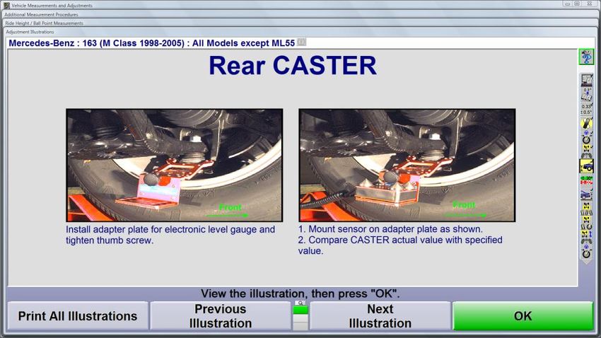

Contents
CONTENTS .............................................................................................................................................................. I
GETTING STARTED ................................................................................................................................................. 1
   1.1 INTRODUCTION ........................................................................................................................................................ 1
   1.2 OPERATING THE CONSOLE.......................................................................................................................................... 2
POSITION CONTROL SYSTEM (MKS)....................................................................................................................... 5
   2.1 MKS INTRODUCTION ................................................................................................................................................ 5
   2.2 SENSOR SETUP USING SPECIAL ADAPTORS OR MOUNTING ............................................................................................... 5
   2.3 MKS OPERATION..................................................................................................................................................... 6
PRE-ALIGNMENT OPERATION ................................................................................................................................ 8
   3.1 PRE-ADJUSTMENT .................................................................................................................................................... 8
   3.2 LOGON ................................................................................................................................................................... 8
   3.3 BEGIN ALIGNMENT ................................................................................................................................................. 10
   3.4 WORK ORDER ....................................................................................................................................................... 10
   3.5 SELECTING VEHICLE ALIGNMENT SPECIFICATION ........................................................................................................... 12
   3.6 EDIT TIRE INFORMATION ......................................................................................................................................... 13
   3.7 VEHICLE SPECIFICATION DISPLAY ............................................................................................................................... 13
ALIGNMENT MEASUREMENTS..............................................................................................................................14
   4.1 COMPENSATION CONTROL ....................................................................................................................................... 14
   4.2 CASTER AND S.A.I. MEASUREMENT ........................................................................................................................... 16
   4.3 “BEFORE” MEASURE MAXIMUM STEERING ANGLE ....................................................................................................... 16
   4.4 “BEFORE” TOE MEASUREMENT WITH PRESSER BAR ...................................................................................................... 17
   4.5 “BEFORE” RIDE HEIGHT / BALL POINT MEASUREMENTS ................................................................................................ 18
   4.6 ELECTRONIC DATA ENTRY WITH ELECTRONIC LEVEL GAGE .............................................................................................. 19
   4.7 RIDE HEIGHT VS. SPECIFICATIONS .............................................................................................................................. 21
   4.8 “BEFORE” MEASUREMENTS OVERVIEW ...................................................................................................................... 24
   4.9 “AFTER” RIDE HEIGHT / BALL POINT MEASUREMENTS .................................................................................................. 24
ALIGNMENT ADJUSTMENTS .................................................................................................................................25
   5.1 REAR CASTER ADJUSTMENT ..................................................................................................................................... 25
   5.2 ADJUST REAR CAMBER AND TOE ............................................................................................................................... 25
   5.3 ADJUST FRONT CAMBER AND CASTER ........................................................................................................................ 26
   5.4 MAKE ADDITIONAL ADJUSTMENTS ............................................................................................................................ 27
   5.5 FRONT TOE PRESSED ADJUSTMENT ............................................................................................................................ 29
VERIFY AND DOCUMENT MEASUREMENTS ..........................................................................................................30
   6.1 CASTER AND S.A.I MEASUREMENT (RE-MEASURE) ....................................................................................................... 30
   6.2 MEASURE MAXIMUM STEER ANGLE (RE-MEASURE) ..................................................................................................... 30
   6.3 “AFTER” MEASUREMENTS OVERVIEW........................................................................................................................ 31
   6.4 SAVE CURRENT WORK ORDER .................................................................................................................................. 31
   6.5 PRINT ALIGNMENT ................................................................................................................................................. 31
   6.6 RESETTING THE ALIGNMENT SOFTWARE ..................................................................................................................... 31
PROGRAM DETAILS ..............................................................................................................................................33
   7.1 SAVING CURRENT WORK ORDER ............................................................................................................................... 33
   7.2 VIEWING A PREVIOUS WORK ORDER ......................................................................................................................... 33

      i Contents                                                                  WinAlign Operation Instructions for Mercedes-Benz Aligner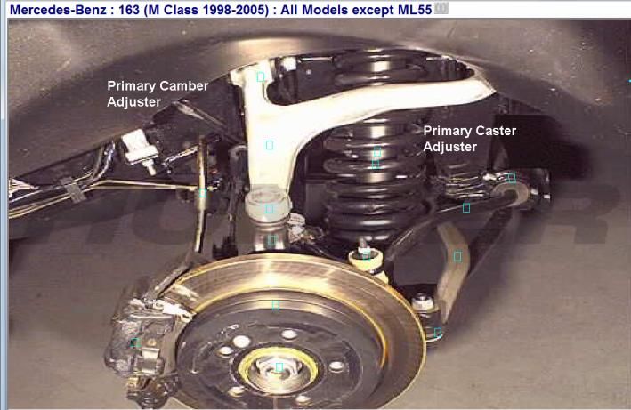
7.3 EQUIPMENT PREPARATION FOR MKS TEST .................................................................................................................. 34
   7.4 SETTING MKS MEASUREMENTS TO ZERO .................................................................................................................... 34
   7.5 MKS TEST ............................................................................................................................................................ 34
   7.6 REVERSE SENSOR TEST............................................................................................................................................. 35
   7.7 TYPES OF LOGON .................................................................................................................................................... 38
   7.8 WHEEL OFF ADJUST ................................................................................................................................................ 39
TOOLS AND ACCESSORIES ....................................................................................................................................40
GLOSSARY ............................................................................................................................................................42
Getting Started
1.1 Introduction
This manual provides information and operation instructions required to operate the
Mercedes-Benz Computerized Wheel Alignment System.
This manual assumes that you are already familiar with the basics of wheel alignment.
“Italics” are used to refer to specific parts of this manual that provide additional information
or explanation. For example, refer to “Vehicle Specifications,” page 30. These references
should be read for additional information to the instructions being presented.
These Mercedes-Benz Operation Instructions are a supplement to the standard WinAlign
Operation Manual supplied with this equipment.
Turning Power On
Turn the unit "ON" by pressing the power switch located on the left side panel, or on the
back panel of the aligner cabinet. The "Logo" screen will appear and indicate that the unit is
ready for use. This will take approximately 1.5 minutes.
Mercedes-Benz Account
The Mercedes-Benz logo screen is only displayed when the Mercedes account is
activated. The "WinAlign" logo is shown when the standard account is activated.
The "Mercedes-Benz" account includes specific procedures required by Mercedes-Benz
and is intended for use by authorized BMW dealers.
The selection process starts at the Mercedes-Benz logo screen. There are four possible
selections on the first level of keys that are displayed on this screen:
K1 - Exit Aligner K2 – MKS K3 - Pre-Adjustment K4 - Begin Alignment
"Exit Aligner" is activated by selecting the K1 softkey. Always press “Exit Aligner” before
turning the power off to shutdown the system.
"Begin Alignment" is activated by pressing the K4 softkey. The green highlight indicates
this is the logical next step in the alignment process.
WinAlign Operation Instructions for Mercedes-Benz Aligner Getting Started 1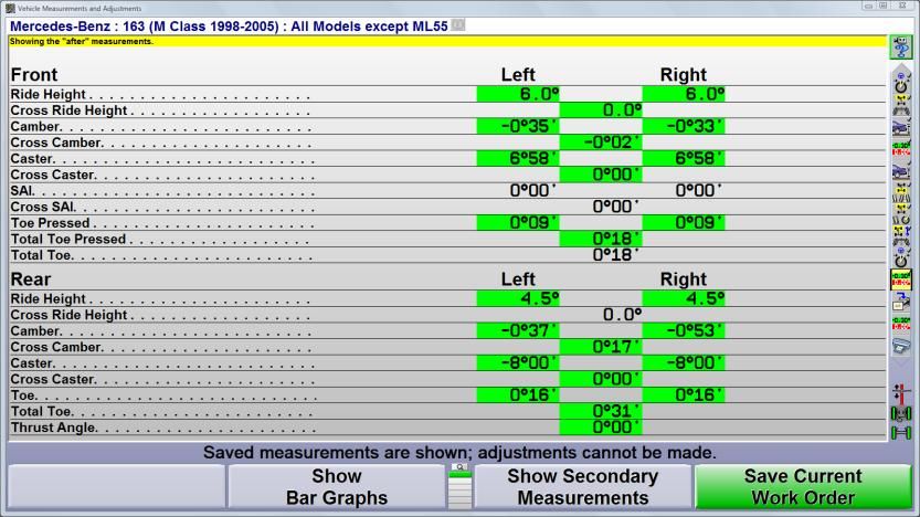
1.2 Operating the Console
Using “Softkeys”
The softkeys, located on the keyboard, provide operator control of the program. These
keys are identified as:
K1 key Forward key
K2 key Backward key
K3 key Zoom key (keyboard)
K4 key Zoom softkey (screen display)
Menu shift key Forward key
Reset key
The four menu labels that appear at the bottom of each screen are referred to as the
softkey labels. These labels indicate the action that the program will take when the
corresponding K1 , K2 , K3 , or K4 key is pressed.
The vertically stacked squares between the K2 and K3 softkeys indicate how many
levels of menu labels are available. Six levels of menus are possible. The highlighted box
indicates the menu level that is currently displayed.
Pressing the menu shift softkey, , changes the menu level. When this key is pressed,
the menu labels will change to the next level “down.” If the last menu level is currently
displayed, the next step will be to the first menu level. To go to the next menu level “up,”
press Shift and .
Pressing Shift and F6 will enlarge the current softkey menu level. The softkey
associated with the label is shown on the left side of the labels and the menu level is
indicated on the right side of the labels. Pressing F6 again will cause the menu to return to
the normal softkey setting.
Pressing F6, or pressing and holding with a pointing device on the menu level indicator, will
cause all of the menus available to appear. The dark green color, displayed behind the
entire row of softkeys, indicates the active menu level. Pressing F6 again will cause the
menu to return to the normal softkey setting.
Throughout this manual, the statement Press “nnnnnnn” indicates the label of the softkey
to press. If the required label is not on the current menu, must be pressed to change
menu levels until the desired label is displayed.
WinAlign Operation Instructions for Mercedes-Benz Aligner Getting Started 2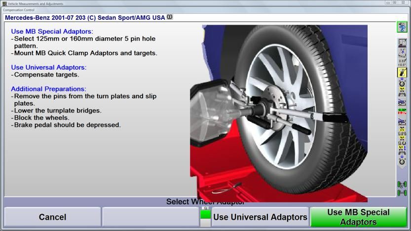
Some softkey labels have a green border as depicted around the K4 softkey shown above.
Generally, the softkey with the green border (usually K4 ) is the appropriate key to press
to continue with the procedure being performed.
Using the Handheld Infrared Wireless Remote Control
®
The remote control provides operation of the WinAlign program from a distance by
duplicating the five softkeys.
The remote control has six softkeys: K1 , K2 , K3 , K4 , , and a zoom key
. Pressing will enlarge the current softkey menu level and is equal to pressing
Shift and on the main keyboard.
To use the remote control, point the front end of the transmitter toward the front of the
wheel aligner console and press the appropriate softkey.
NOTE: The remote control transmitter is a “line-of-sight” device and will not transmit
signals through solid objects.
Resetting the Program
The wheel alignment program may be reset Error! Bookmark not defined. at any time
during the measurement process by pressing the R key, located at the upper
left-hand corner of the keyboard.
A confirmation screen will appear to verify that the “Reset” button was pressed
intentionally.
When this screen appears, press “YES” to reset the program or “NO” if the program should
not be reset.
When the aligner is reset, the information collected for the measurements in progress will
be erased and the display will return to the “BMW Logo” screen.
cedes-Benz Logo” screen.
WinAlign Operation Instructions for Mercedes-Benz Aligner Getting Started 3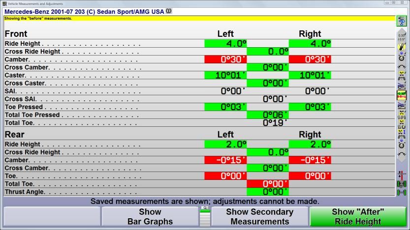
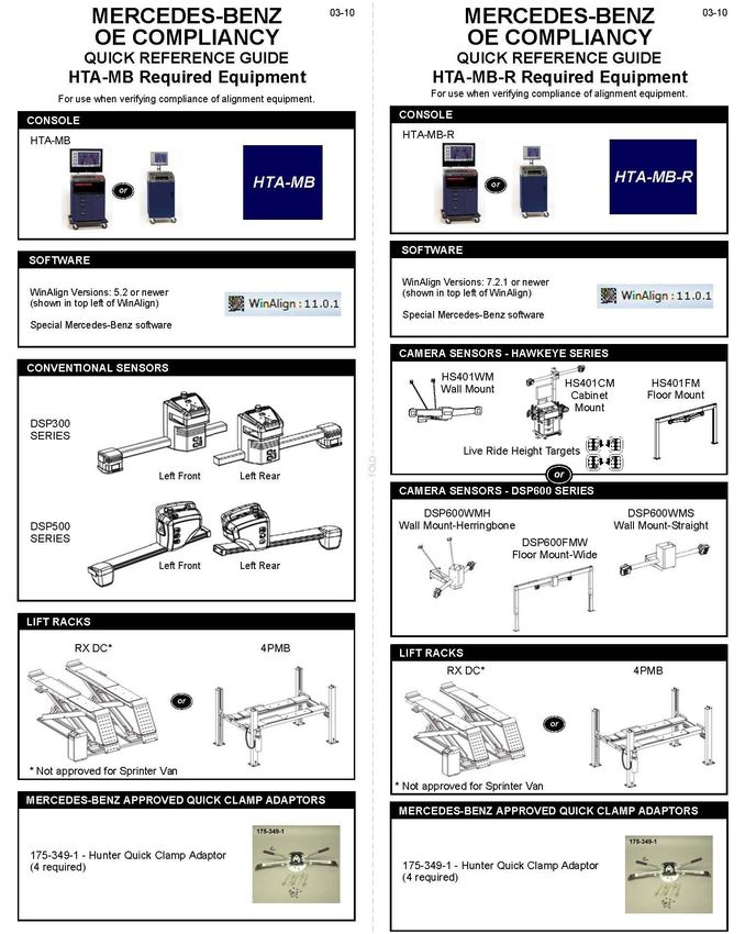
NOTE: The following diagrams indicate the current Mercedes-Benz compliant Hunter
Alignment Equipment as of this document's print date. Always check current sources for
the latest information.
As of August 2011, the approved camera systems include Hunter
Engineering's DSP600 sensors and HS401 sensors
WinAlign Operation Instructions for Mercedes-Benz Aligner Getting Started 4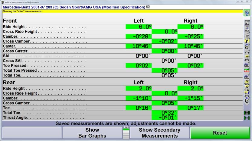
Position Control System (MKS)
2.1 MKS Introduction
MKS is a Mercedes-Benz procedure that may be used to monitor the precision of the wheel
alignment lift rack and sensors.
The lift rack must be equipped with MKS mounting brackets in order to make use of this
procedure and to obtain valid MKS measurements.
2.2 Sensor Setup Using Special Adaptors or Mounting
Indexing Electronic Sensors
Before mounting the sensors on the Mercedes-Benz special adaptors or MKS brackets,
rotate the index mark on the sensor shaft to the 12 o’clock position with the sensor held
vertical and lock it in place using the sensor lock knob. Do not loosen the sensor lock knobs.
INDEX
MARK
SENSOR
LOCK
KNOB
WinAlign Operation Instructions for Mercedes-Benz Aligner Position Control System (MKS) 5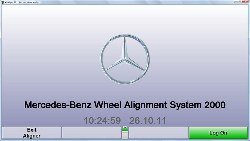
When instructed to level the sensors, do so only by loosening the locking lever or lock knob on the adaptor, not the lock knob on the sensor. Refer to “Leveling and Locking Sensors." For sensors mounted to the Mercedes-Benz special adaptors, the sensors are secured at the “level” position by tightening the lock knob on the bracket or wheel adaptor, rather than the lock knob on the sensor. Verify that the index mark of the sensor shaft is at the 12:00 o’clock position. Vision System Reflectors Install the reflectors on the special adaptors or in the MKS brackets. Level the sensor using the bubble level or align the arrows vertically depending on the style of reflector. Secure the reflector shaft using the adaptor lock mechanism. 2.3 MKS Operation The level of the lift rack and wheel alignment sensors should be calibrated prior to setting the MKS measurements to zero. Refer to “Setting MKS Measurements to Zero." The “Position Control System (MKS)” screen is displayed automatically after the computer boots up when the power is turned on. The MKS screen may also be displayed by pressing the “MKS” softkey located on the Mercedes-Benz logo screen after logging on. WinAlign Operation Instructions for Mercedes-Benz Aligner Position Control System (MKS) 6
By pressing “MKS Information” from the MKS screen, the MKS Help screen will appear.
The measurements that appear on the MKS screen are valid only if the MKS
measurements have been previously measured and set to zero. Refer to “Setting MKS
Measurements to Zero,” page 7.
If the MKS measurements have been previously measured and set to zero, then all
measurements should equal 0 degrees 00 minutes ± 0 degrees 05 minutes.
Measurements that are within this tolerance will be green. Measurements that are outside
of this tolerance will be red.
Green measurements are considered good and the lift rack and sensors are expected to
provide accurate vehicle wheel alignment measuring results.
If red measurements are displayed, then the accuracy of the lift rack and/or sensors are
suspect and it is recommended that the sensors first be checked for accuracy.
If the sensors are found to be accurate, then it is recommended that the lift rack be checked
for accuracy.
NOTE: The wheel alignment program will operate regardless of the MKS measuring
results. Green or red measurements will not prohibit the use of the operating program.
Additional information on the MKS procedure is located on page 33.
WinAlign Operation Instructions for Mercedes-Benz Aligner Position Control System (MKS) 7Pre-Alignment Operation 3.1 Pre-Adjustment This screen allows the user to perform a quick check of primary alignment angles before beginning an actual alignment of the vehicle. 3.2 Logon The logon default is "enabled" for the Mercedes-Benz wheel alignment system. The primary use of Log On option is to allow a user to customize alignment program settings according to his or her preferences in the setup program. The logon capability can be enabled or disabled in the setup program. Additional information about the Logon function is located on page 37. WinAlign Operation Instructions for Mercedes-Benz Aligner Pre-Alignment Operation 8
Logging On
With logon enabled, the “Begin Alignment” key is replaced with “Log On.” Press “Log On.”
The “Logon User List” screen will appear. Select a user and enter the password.
Passwords are not case-sensitive. The logon feature does not distinguish between UPPER
case and lower case letters for any logon names or passwords.
Press or “Select Next Field” to move the cursor to the next field, “Password,”
then enter the password. For each character entered in this field, an asterisk (*) will appear.
This prevents anyone from reading the password off the screen after it has been typed.
If the password is not correct, an error message will appear. Press “OK,” then re-enter the
password.
When a user has logged on successfully, the logo screen will appear with the “Begin
Alignment” key.
Logging Off
Resetting the aligner will not log off a user. Turning the alignment console off will log off a
user. To log off, press “Log Off” on the logo screen.
WinAlign Operation Instructions for Mercedes-Benz Aligner Pre-Alignment Operation 93.3 Begin Alignment
Press “Begin Alignment” to begin the wheel alignment measurement process. The “Work
Management” screen will appear. This screen shows the basic work order information.
3.4 Work Order
Work Management provides a database for storing work orders, customer identification,
and vehicle identification.
A work order may contain the following information fields:
work order number reference to customer identification
reference to vehicle identification technician identification
vehicle mileage note
alignment procedure alignment specifications
alignment measurements tire Information
Work Management provides methods to store and recall customer and vehicle
identification. This identification is then referenced by work orders.
Customer identification includes the following:
customer number first and last name
company name address
home phone work phone
Vehicle identification includes the following:
Vehicle alignment specification vehicle make and model description
identification
VIN license
first registration date
NOTE: Mileage is stored in the work order and not in the vehicle identification.
WinAlign Operation Instructions for Mercedes-Benz Aligner Pre-Alignment Operation 10Entering Customer Identification
Customer information is entered on the “Edit Work Order” screen.
The cursor indicates the position where a letter or number will appear. Enter the required
information by using the keyboard.
Press or to advance to the next field. Press and to back up
to the previous field. The mouse may also be used.
Recalling a Customer/Vehicle
Press “List Work Orders” in the “Work Management” screen to display the “Recall
Customer/Vehicle” screen.
Scroll using the or to highlight the desired customer or use the
search function located below the list of work orders.
The search function will be faster in most cases.
Once the customer/vehicle is identified, press "Use Selected Item" and the
customer/vehicle info is recalled and attached to the current work order.
Additional information about the Work Management function is located on page 32.
WinAlign Operation Instructions for Mercedes-Benz Aligner Pre-Alignment Operation 113.5 Selecting Vehicle Alignment Specification The wheel alignment specifications for the vehicle are typically selected during the process of completing the work order. Three selection methods are available as illustrated below. Mercedes Benz Alignment Specification Database A dedicated Mercedes-Benz specification database is included with WinAlign's MB alignment software. Always use the dedicated Mercedes-Benz specification database. This database includes information and procedures not offered in the standard "Factory USA" database. The Mercedes Benz database is in addition to the "Factory USA" database shipped standard with the WinAlign program. Press “Show Spec Databases” and a list of specification databases will appear. Select the “Factory Mercedes-Benz” database, press “OK,” and then select the model. If you recall Mercedes-Benz specifications from a database other than the “Factory Mercedes-Benz” database, the following warning message will appear. WinAlign Operation Instructions for Mercedes-Benz Aligner Pre-Alignment Operation 12
3.6 Edit Tire Information
Use the keyboard to enter the appropriate data into the “Edit Tire Information” screen. This
information will appear on the printout summary. This data entry process is optional. Press
“OK” to continue.
3.7 Vehicle Specification Display
The “Vehicle Specifications” primary screen allows the operator to view the vehicle
specification data that has been recalled.
Some data fields are intentionally left blank for Mercedes-Benz models. The vehicle
specification data for some of the blank fields will be recalled later during the wheel
alignment measurement process.
Specifications may be manually entered on this screen. Any change to the vehicle
specifications will cause the title of the specification to be changed with "(Modified
Specification)" at the end of the title.
Press ”Mount Sensors” to continue.
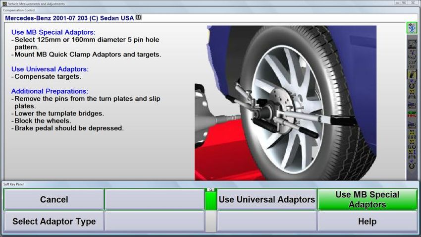
WinAlign Operation Instructions for Mercedes-Benz Aligner Pre-Alignment Operation 13Alignment Measurements 4.1 Compensation Control This screen provides special instructions for universal and Mercedes-Benz special adaptors. Choose a wheel adaptor type before proceeding with the alignment. Additional adaptor type configurations are available through the second row of softkeys. Some measurements require knowledge of the distance between the vehicle's wheel and the alignment sensor. Specifying the attachment method provides the distance value. Universal Adaptors Wheel run-out compensation must be performed when using universal adaptors If the universal adaptor was selected, instructions pertaining to this adaptor are provided on the display screen. The compensation option is displayed along with the vehicle plan view showing the status of the sensors. WinAlign Operation Instructions for Mercedes-Benz Aligner Alignment Measurements 14
Follow the instructions on the display to assure the best compensation possible.
offset adaptors
One or more conventional electronic sensors may be compensated at the same time if multiple people are
available. The center casting of the adapter should be centered on the adaptor rods. The offset adaptors shown
above are available to lower the front sensors if communication between the front sensors is blocked.
Follow these guidelines when performing rolling compensation with vision sensors.
1. Use a rear tire to roll the vehicle during compensation
a. Do not roll the vehicle by pushing or pulling on the front or rear bumper (suspension angles
will change)
b. Do not roll the vehicle using either of the front tires (front wheels will steer during the roll)
2. The gap between the rear of the turnplate and the runway must be filled using the bridges provided
3. Never unlock the sensor shaft from the adaptor during the alignment process
Use Mercedes-Benz Special Adaptors
If Mercedes-Benz special adaptors are selected, the instructions change to show only
those pertinent to these adaptors. The compensation option is displayed along with the
vehicle plan view showing the status of the sensors. Press K-4 “Use MB Special Adaptors”
to advance the procedure.
WinAlign Operation Instructions for Mercedes-Benz Aligner Alignment Measurements 154.2 Caster and S.A.I. Measurement
The caster measurement sequence for the Mercedes-Benz system is set to measure
FasterCaster/SAI/IA/Toe-out-on-turns at 20 degrees.
Follow the instructions given on the screen. The program will wait until all sensors are
stable before automatically moving to the next screen. This is necessary because all live
“Before” measurements for the sensors are saved at this time.
Steer the wheels as directed by the bar graphs.
NOTE: Steering past the intended steer angle will result in a bar graph directing the front
wheels to be steered back to the side of original entry. This is designed to assure
consistent measurements.
If any sensor is not level during the final steer ahead, a warning will appear at the end of the
procedure and the steering sequence must be repeated.
4.3 “Before” Measure Maximum Steering Angle
The “Measure Maximum Steering Angle” measurement screen will appear next, if the
vehicle specification includes a maximum steer angle preferred specification and
tolerance. WinAlign will bypass this measurement if the vehicle's specification does not
include a preferred specification and tolerance for maximum steering angle.
WinAlign Operation Instructions for Mercedes-Benz Aligner Alignment Measurements 164.4 “Before” Toe Measurement with Presser Bar
Follow all of the instructions on the screen and then press “Save Toe Pressed.” The front
toe pressed measurements are saved to “Before” measurements at this time.
The operator is instructed to remove the toe presser bar. Press “OK.” Normal front toe is
measured and saved to “Before” measurements at this time.
WinAlign Operation Instructions for Mercedes-Benz Aligner Alignment Measurements 174.5 “Before” Ride Height / Ball Point Measurements
Alignment angle specifications may be based on measurements entered on this display.
This screen allows the entry of vehicle Ride Height, Ball Point, Control Point, Rear Caster
and/or Front Shock Tube Length measurements, depending on the vehicle that has been
recalled from the specification database.
Linear vs. Angular measurements
Mechanical ride height measurement tools may be required to measure ride height, ball
point and control point on older Mercedes-Benz models. Models manufactured since 1998
may utilize mechanical measurement tools or the Electronic Level Gage.
New models, such as the A class, do not utilize the mechanical measurement tools. Ride
height on these newer models is measured only in decimal degrees using the Electronic
Level Gage.
Appropriate measurement tools must be used to obtain these measurements.
R
o
The data may be manually or electronically entered into the appropriate fields providedmon
this screen. e
s
Press “Save ‘Before Ride Height” after all data entries have been entered. s
The remaining vehicle specs will be recalled from the specification database when thisI
n
data is saved. c
l
i
n
o
WinAlign Operation Instructions for Mercedes-Benz Aligner Alignment Measurements
m 18
e
t
e
r4.6 Electronic Data Entry with Electronic Level Gage
Front and rear ride height measurements, along with rear caster measurements obtained
with the Electronic Level Gage may be electronically transmitted to the wheel aligner.
Rear Control Point may be measured with the Electronic Level Gage, however this
measurement must be entered manually into the wheel aligner. Refer to the operation
instructions provided with the Electronic Level Gage to obtain the angular measurements.
Illustrations of the ride height measurement point are made available for some models by
pressing the “Illustrate Adjustments” softkey.
Measure and store the front and/or rear ride height measurements using the electronic
level gage and adaptors.
Connect the Electronic Level Gage to the appropriate port on the wheel aligner using the
cable or docking station provided with the wheel aligner.
After connecting the Electronic Level Gage to the wheel aligner,
Press the “Memory” key on the face of the Electronic Level Gage
Press the “Transfer Ride Height” or “Transfer Rear Caster” softkey.
If the transmission is successful, the appropriate fields will display the data received from
the Electronic Level Gage and the data will be erased from the Electronic Level Gage. The
“Transfer” softkeys will not be displayed if the vehicle cannot be measured with the
Electronic Level Gage.
WinAlign Operation Instructions for Mercedes-Benz Aligner Alignment Measurements 19Rear Caster (Data Entry with Electronic Level Gage) Rear caster is measured by attaching the rear caster adaptor bracket to the rear knuckle assembly and placing the angle gage on the adaptor. Measure and store the left and right rear caster measurements using the Romess tool. After measuring the rear caster, connect the Electronic Level Gage to the aligner, the measurements may be transmitted to the aligner by pressing “Transfer Rear Caster.” NOTE: When transferring rear caster measurements from the Electronic Level Gage, make sure that the rear caster measurement data has been entered in the fields that are normally used to measure rear ride height on the Electronic Level Gage. WinAlign Operation Instructions for Mercedes-Benz Aligner Alignment Measurements 20
4.7 Ride Height vs. Specifications
Press the “Show Camber/Caster Specs” softkey to view the correlation between ride height
and the camber or caster specifications. If desired, you may also view the camber/caster
specs.
The caster tables utilize the front and rear ride height to determine the front caster
specification. The Mercedes 204 is an example of a vehicle with ride height dependent
front caster. An example is shown below:
Using the table shown above, a front ride height of –4.28. degrees and a rear ride height of
–7.99 degrees corresponds to a front caster specification of +13 degrees 07 minutes.
WinAlign Operation Instructions for Mercedes-Benz Aligner Alignment Measurements 21Manual Entry of Ride Height Data Manual front ride height measurement Check front ride height by placing the 201 589 00 21 00 tool between the two eccentrics on the lower control arm. Position the contact arm on the lower control arm. Enter the angle from the scale indicated by the weighted string in the appropriate portion of the screen. Manual rear ride height measurement Rear ride height is manually checked by placing the pivot arm of the measuring device on the spring link (control arm bushing) of the inner control arm mount. Place the pointer on the rear axle shaft. Enter the angle from the scale indicated by the weighted string in the appropriate portion of the screen. Adjustments to vehicle level may be made changing the spring's rubber mount. A change of the rubber mount by 5mm results in a vehicle level change of approximately 9mm. On vehicles with level control, do not correct vehicle level by changing the connecting rod of the level controller (control point). Check level control for proper function. Inspect springs and rubber mounts WinAlign Operation Instructions for Mercedes-Benz Aligner Alignment Measurements 22
Manual Entry of Ball Point Data
Ball Point measurement may be obtained by utilizing the mechanical measurement tools
and are always entered in millimeters.
Measure ball point position by placing
Mercedes Benz tool 201 589 00 21 00
between the two eccentrics on the lower
control arm. Position the contact arm on the
lower control arm such that the plumb bob is
at zero on the scale.
With the front wheels in the straight ahead
position, slide part O1b to contact threaded
portion of inner tie rod. Difference in height
"A" = ball joint position. The ball joint
position is not measured directly but via
dimension "a".
Ball point position may be adjusted at the
Idler arm by inserting an additional washer
or by removing a washer. Enter the distance
in millimeters for the left and right ball point
measurement.
Manual Entry of "Control Point"
Control point is a manual ride height measurement of the rear suspension. A linear
measurement may be entered in millimeters. The measurement records the height
difference between the center of the lower control arm bolt and the bottom edge protective
ring of the wheel carrier bearing of semi-trailing arm. .
This measurement may also be recorded as an angle using Mercedes tool 107 589 01 21
00 or with 107 589 02 21 00
WinAlign Operation Instructions for Mercedes-Benz Aligner Alignment Measurements 234.8 “Before” Measurements Overview “Before” adjustment measurements that have been saved are shown here. Front camber values are measured at “0 degree toe.” If an angle is not shown as compared to a specification, then it may not have a specification. NOTE: Whenever the following Vehicle Measurements and Adjustments Screen is shown, the values are “frozen.” Pressing “Show After Ride Height” begins the vehicle adjustment process. 4.9 “After” Ride Height / Ball Point Measurements The initial measurements shown on this screen are the same as the measurements that appeared on the “Before” Ride Height / Ball Point / Control Point screen. The data on the “After” measurement screen can by edited if any value was changed during the adjustment process. Ride height measurements transferred from the Electronic Level Gage cannot be manually edited. New measurements must be made and transferred from the Electronic Level Gage. Pressing “Save After Ride Height” will re-calculate the ride height dependent specifications according to the “After” ride height values. Saved ride height data will appear in the “After correction” column on the printout summary. WinAlign Operation Instructions for Mercedes-Benz Aligner Alignment Measurements 24
Alignment Adjustments
5.1 Rear Caster Adjustment
Rear caster adjustments require the electronic level gage and caster bracket.
Rear caster adjustments on the M63 platform requires moving the rear upper control arm,
which also controls rear camber. The rearmost adjuster is primarily responsible for tilting
the top of the steering axis forward or rearward.
F
r
o
n R
t e
a
o r
5.2 Adjust Rear Camber
f and Toe
c
a
V
s
Adjustments may be made toe rear camber and toe at this screen. Rear camber should be t
adjusted before rear toe. h e
i r
c
l m
e e
a
s
u
r
e
m
e
n
t
Place the mouse pointer on the symbol in the lower left corner of any bar graph and hold
the left mouse button down for one second. A menu will appear offering helpful functions
associated with the angle represented on the bar graph.
WinAlign Operation Instructions for Mercedes-Benz Aligner Alignment Adjustments 25Jack Up Axle is used to make rear camber adjustments easier
Illustrate Adjustments and animation are helpful in identifying the
adjustment type and location
Tools and Kits offers hand tools and aftermarket kits needed to
make the adjustment
Set Up Bar Graph Groups offers additional rear bar graph
designs
Adjust to Zero changes the values on the bar graphs to indicate
how far away the angle is from preferred specification
Adjust to Half Tolerances changes the bar graph to yellow when
the measurements is the outer portion of the tolerance area.
5.3 Adjust Front Camber and Caster
Do not re-level the front sensors before adjusting camber or caster.
The vehicle's service brakes must prevent the front wheels from rolling when adjusting
caster.
The front caster adjustment values change as the front of the alignment sensor rotates
upward or downward. With the front brakes applied, the front of the sensor rotates upward
as the top of the steering axis is tilted rearward (caster increase).
If the front brakes are free, the front wheels may roll causing the sensor to rotate and
change the value on the caster adjust bar graphs. To correct this problem, go to the third
row of soft keys and select "Measure Caster." Measure the caster angle again to establish
good adjustment values before adjusting front caster.
WinAlign Operation Instructions for Mercedes-Benz Aligner Alignment Adjustments 26Front individual toe must be at zero when making adjustments to front camber
and/or caster.
The high amount of positive caster specified on many Mercedes
Benz vehicles causes extreme changes in front camber as the front
wheels steer left or right of zero toe.
Maintaining front individual toe at zero when adjusting camber
and/or caster will ensure the desired results after the adjustment to
camber and/or caster is complete.
Red arrows on the camber bar graphs indicate toe has not been
adjusted to zero and the camber adjustment bar graph will not
function.
Setting individual toe to zero will "unlock" the camber bar graph.
5.4 Make Additional Adjustments
Additional adjustment help may be found by selecting "Make Additional Adjustments" from
the soft key menu.
Helpful adjustment procedures for the vehicle selected will be displayed in a list.
WinAlign Operation Instructions for Mercedes-Benz Aligner Alignment Adjustments 27The 163 M Class vehicle requires the upper control arm to be adjusted. The CAMM program will help make this adjustment easier. The option of adjusting the control arm with the front wheel removed is also available. An optional adaptor is available for "Wheel Off" adjustments. Select "Jack Up Front Wheels" when making adjustments to upper control arms. Follow the instructions on the display, Select "Lower Wheels and Finish" to complete the procedure. WinAlign Operation Instructions for Mercedes-Benz Aligner Alignment Adjustments 28
5.5 Front Toe Pressed Adjustment
After installing the toe presser bar, adjust front toe while the steering wheel is locked in the
straight-ahead position.
Remove the toe presser bar.
WinAlign Operation Instructions for Mercedes-Benz Aligner Alignment Adjustments 29Verify and Document Measurements 6.1 Caster and S.A.I Measurement (Re-measure) This steering sequence is performed again to measure “After” caster, SAI, IA, toe-out-on-turns and camber at 0 degrees toe. The program will wait until all sensors are stable before saving all “After” measurements. 6.2 Measure Maximum Steer Angle (Re-measure) The final maximum steer angle is measured at this time, if the vehicle's specification includes a preferred specification and tolerance. WinAlign Operation Instructions for Mercedes-Benz Aligner Verify and Document Measurements 30
6.3 “After” Measurements Overview
Final alignment measurements are displayed for review and will be recorded as the “After
Correction” measurements on the final print summary. Front camber values are at zero
degrees toe.
6.4 Save Current Work Order
Press “Save Current Work Order” to memorize all data pertaining to this job.
6.5 Print Alignment
Select “Print Summary“ to print "Before" and "After" measurements using the MB printout
format.
6.6 Resetting the Alignment Software
Select the K-4 “Reset" softkey to return to the initial alignment procedure screen. All
information not saved through the work order will be erased in preparation for the next
alignment process.
WinAlign Operation Instructions for Mercedes-Benz Aligner Verify and Document Measurements 31WinAlign Operation Instructions for Mercedes-Benz Aligner Verify and Document Measurements 32
Program Details

           7.1 Saving Current Work Order

           Find and press “Work Management” softkey. Search the available softkeys to find and select the
           “Save Current Work Order” softkey. Press this softkey to save the work order and store it on the
           hard drive.

           If the current work order customer/vehicle identification was not recalled from the database, new
           customer/vehicle identification is created and attached to the current work order.
           If the current work order customer/vehicle identification was recalled from the database, any
           customer/vehicle identification changes (for example a new address or phone number) would
           replace the customer/vehicle identification. All work orders for this customer/vehicle will be
           updated.
           The “Save Current Work Order” softkey will also appear at the end of the alignment
           measurement procedure and on the “Print” screen.

           7.2 Viewing a Previous Work Order

           From the Work Management display, find and press “List Work Orders” softkey. Highlight the
           desired work order to be viewed.

WinAlign Operation Instructions for Mercedes-Benz Aligner                                      Program Details 33
Display all of the softkeys available and select to show the "Before" or "After" alignment
measurements for the work order selected.
Print the measurements, if desired.
7.3 Equipment Preparation for MKS Test
1. Set the lift rack to the fully lowered, drive-on position.
2. Drive a vehicle onto the lift rack.
3. The runways of the lift must be leveled, when completely lowered and at all working
positions, to less than or equal to 1 mm.
4. Install the wheel alignment sensors onto the appropriate MKS brackets located on the
side of the lift rack runways.
5. Connect all sensor cables (if required) and turn all sensor power switches on.
6. Level and lock the sensors. Refer to “Leveling and Locking Sensors,” page 3.
7. Turn the system “ON” by pressing the power switch located on the back of the console
where the AC power cord is connected to the cabinet.
7.4 Setting MKS Measurements to Zero
MKS measurements may be set to zero only after the “Manager” has logged on
MKS measurements may not be set to zero if a “User” is logged on, or if the “Logon
Enable” feature is disabled.
The Mercedes-Benz logo screen will be displayed after logging on to the system using
the “Manager” name and password.
Press “MKS” to display the “Position Control System (MKS)” screen.
Press “Zero” to set all of the measurements to 0 degrees 00 minutes. The Zero Date will
be set to the current time and date.
7.5 MKS Test
Position Control System (MKS) for wheel alignment facilities
NOTE: The MKS test is not to be used to adjust the toe and camber transducers in the wheel
alignment sensors or to level the runways of the lift or pit.
Set the lift rack to the fully lowered, drive-on position.
Drive a vehicle onto the lift rack.
WinAlign Operation Instructions for Mercedes-Benz Aligner Program Details 34Install the wheel alignment sensors onto the appropriate MKS brackets located on the side of
the lift rack runways. Refer to “Sensor Indexing,” page 3.
Connect all sensor cables (if required) and turn all sensor power switches on.
Level and lock the sensors. Refer to “Leveling and Locking Sensors,” page 3.
Turn the system “ON” by pressing the power switch located on the back of the console where
the AC power cord is connected to the cabinet.
Thereafter, before performing wheel alignment measurements, the values displayed on the
MKS screen must not be greater than or equal to 5 minutes while the sensors are installed in the
MKS brackets as described above.
If any value is out of tolerance, then the lift and wheel alignment system must be checked.
Checking procedure
1. Checking the level of the lift:
Drive a vehicle onto the turn plates and slip plates. Install the brake-pedal depressor. Remove
the safety pins from the turn plates and slip plates. Install wheel adaptors and sensors on the
wheels. Compare camber and toe measurements with the lift completely lowered and in the
raised working position (refer to Quality report Q40.2 / 9.1). Permitted differences less than or
equal to 2 minutes. In cases where the tolerance has been exceeded, the level of the lift must be
adjusted by the lift manufacturer or by the manufacturer’s service representative.
2. Checking the wheel alignment sensors:
Perform a reverse sensor test to determine if the wheel alignment sensors are measuring
accurately. Refer to “Reverse Sensor Test,” page 8. Differences must be less than 5 minutes
(refer to Quality Report Q40.2 / 7.6). If differences exceed this tolerance, then the wheel
alignment sensors must be calibrated.
7.6 Reverse Sensor Test
The Reverse Sensor Test is a quick check of the calibration of a set of sensors. This test is
applicable to all versions of DSP306, DSP308, DSP506 and DSP508 sensors that have been
calibrated using the long calibration bar.
The Reverse Sensor test is also applicable to DSP400, DSP600 and HS401 Hawkeye vision
sensors.
Begin the test by turning on the sensors and selecting the “Reverse Sensor Test” softkey from
the Service Programs screen. The Reverse Sensor Test will be available only if applicable
sensors are in use. Follow the on-screen instructions to carry out the test.
WinAlign Operation Instructions for Mercedes-Benz Aligner Program Details 35Before mounting the sensors on the Mercedes-Benz special adaptors, rotate the index mark on the sensor shaft to the 12 o’clock position with the sensor held vertical and lock it in place using the sensor lock knob. Do not loosen the sensor lock knobs for the remainder of the test. When instructed to level the sensors, do so only by loosening the locking lever or lock knob on the adaptor, not the lock knob on the sensor. Refer to “Leveling and Locking Sensors,” page 3. Follow the on-screen instructions, then press “Ready.” When instructed to steer the vehicle, steer as precisely as possible to zero degrees, then use care to not disturb the steering for the remainder of the test. Level and lock the sensors using the wheel adaptor lock knobs, after the wheels have been steered to zero degrees. Follow the on-screen instructions, then press “Ready.” Refer to “Leveling and Locking Sensors.” WinAlign Operation Instructions for Mercedes-Benz Aligner Program Details 36
This test assumes that the vehicle or wheel adaptors do not move during the test procedure.
           When moving sensors to the opposite axle, detach the sensors from the wheel adaptors,
           leaving the wheel adaptors mounted to the wheels on which they were originally mounted.
           Carefully insert the sensors into the wheel adaptors, being careful to not disturb the vehicle or
           the wheel adaptor.

           When the test has been completed, four values will be displayed showing toe and camber
           differences. Measurements of 0 degrees 00 minutes ± 0 degrees 05 minutes will be green.
           Measurements outside of this tolerance will be red.

WinAlign Operation Instructions for Mercedes-Benz Aligner                                       Program Details 37
If any of the values are shown in red, the sensors need to be calibrated. Failing to carry out the proper procedures described above and in the on-screen instructions may cause incorrect readings and produce a false indication that calibration is needed. NOTE: Measurements from the Reverse Sensor Test are saved to the hard drive and may be imported into the Mercedes-Benz Quality Report Database Software (Version 3.1 or higher). 7.7 Types of Logon The logon feature supports two different types of logons - manager and user. The person designated to be the administrator for the system typically uses the MANAGER logon. Manager Logon There is only one logon name called “MANAGER.” The “MANAGER” logon cannot be deleted or renamed and is typically assigned to the owner, service manager, or supervisor. The manager logon has more setup items than the user logons and is the only logon that can enable or disable the logon feature or add, change, or delete other user logons. NOTE: The password for the MANAGER is MANAGER. After logon is enabled, the password for the “MANAGER” logon should be changed. Please record the new password for future use. User Logon A user is anyone who performs alignments using the WinAlign program. A logon may be created for each user. Typically, each alignment technician would be assigned and use their own user logon. Setup Items When a user is logged on and changes a setup item, the change affects only the program structure for that specific user. However, when a setup item is changed using the manager logon, the change affects all users with logons that have not set up the item selected by the manager. Logon Registry When logon is enabled, only the users that appear in the logon registry may log on to WinAlign. Users may be added to or deleted from the logon registry by using the “Set Up Aligner” function. Only the MANAGER can add or delete from the logon registry. WinAlign Operation Instructions for Mercedes-Benz Aligner Program Details 38
The registry contains the following information for each user that has been assigned a logon
           name:

             Logon Name                      A short name used to identify the user. This name is what the user
                                             types into the “Logon” popup screen.

             Full Name                       The user’s full name. This name will appear on the Customer ID
                                             screen as the Technician and on the reset screen as the current
                                             user.

             Password                        A password to protect the user from having his identity
                                             misrepresented. Passwords are never displayed and can be left
                                             blank.

             User Number                     A number representing each user in the database.

           NOTE: A user may change his or her password. Only the manager logon may add, change, or
           delete user logons from the registry.

           7.8 Wheel Off Adjust
           Front camber, front caster and rear camber may be adjusted with the vehicle's tire lifted off the
           runway and the wheel removed.

           This function may be accessed through a softkey called "Make Additional Adjustments" or from
           the camber or caster context sensitive drop menu.

WinAlign Operation Instructions for Mercedes-Benz Aligner                                         Program Details 39
Tools and Accessories
Mandatory Tools for all Mercedes-Benz USA Consoles
These tools must be ordered from MBUSA
MB Quick Clamp Adaptor x 4- (or Hunter MB approved quick clamp alternative listed under
124 589 01 31 00
Mercedes Specific Options)
199 589 00 31 00 SLR (199) Pin Set for fastening the M-B Quick Clamp Adapter to the rear axle (10 pcs)
211 589 00 31 00 Adapter, Brake Pedal Winch (211, 230)
000 589 18 31 00 Brake Pedal Depressor
129 589 01 21 00 Steering Wheel Holder
900 589 01 27 00 Toe Rod (spreader bar)
900 589 03 21 00 M Class Adaptor Front (accessory for Mercedes Electronic Level Gauge)
900 589 04 21 00 M Class Adaptor Rear (accessory for Mercedes Electronic Level Gauge)
900 589 01 21 00 Mercedes Electronic Level Gauge (Electronic Ride Height Tool)
230 589 01 09 00 Lug Socket for assembling and disassembling AMG multispoke wheel
230 589 03 31 00 AMG Pin Set for fastening the MB Quick Clamp Adaptor to the rear axle (10 pieces)
900 589 17 21 00 Support for Data Transfer and Charging Station Tool (DTCS)
900 589 16 21 00 Maybach Front Adapter (Maybach Dealers Only)
Optional Tools for all Mercedes-Benz USA Consoles
These tools must be ordered from MBUSA
900 589 02 21 00 Data Transfer Station (docking station for Mercedes Electronic Level Gauge)
Standard Accessories with MB DSP500 Sensors
Pair of electronic turnplates with
20-1786-1
protective covers
DSP500 Quick Clamp Adaptor
20-1899-1
Support Kit
20-1913-1 Offset Adaptor used to clear spoilers
WinAlign Operation Instructions for Mercedes-Benz Aligner Tools and Accessories 40Standard Accessories with MB HS421 Sensors
20-1963-1 50 mm Turnplates Bridges
DSP500 Quick Clamp Adaptor
20-1899-1
Support Kit
Optional accessories DSP600 and HS4X1 Camera Based Sensor systems
Icon Remote Indicator New style remote indicator
30-419-1
30-421-1 Icon Cordless Remote
New style cordless remote indicator
Indicator
New style cordless remote indicator.
Records tire pressure, tread depth, ride
Plus Cordless Remote
height and measures tire temperature
Indicator
30-418-1 and frame angle. Includes Tire
Temperature Probe.
XF communication for use with Plus
Cordless Remote Indicator, 30-418-1-1
XF2 Pod Kit
and Icon Cordless Remote Indicator,
20-2072-1 30-421-1.
Wheel-Off adaptor may be used to make
adjustments to camber and caster with
Wheel-Off Adaptor
wheel removed. Magnetic version also
20-1978-1 20-1979-1
The following accessories are available for older wheel adaptor configurations
Compatible only DSP600 and HS4X1
External tire clamp adaptor self-centering adaptors 175-321-1 or
175-325-1.
20-1789-1
WinAlign Operation Instructions for Mercedes-Benz Aligner Tools and Accessories 41Glossary
Alignment The process of measuring and positioning all wheels attached to a common
chassis
Angle Two intersecting lines
Camber: The inward or outward tilt of the top of the wheel as viewed from the
front
Camber roll: The change in front camber in a turn due to caster
Caster: The forward or rearward tilt of the steering axis as viewed from the
side
Degree: A unit of measurement used to describe an angle.
Directional stability: The tendency for a vehicle to maintain a directed path.
Dog tracking: The appearance given when the thrustline is not parallel with the
centerline of the vehicle.
Drift (lead): The tendency of a vehicle to steer away from a directed course.
Less severe than a pull, constant pressure at the steering wheel is
not needed to maintain straight ahead.
Geometric centerline: A line drawn through the midpoint of both front wheels and both rear wheels.
Included angle: S.A.I. plus camber
Individual toe: The angle formed by the intersection of an individual line drawn
through the plane of one wheel and the centerline.
Max Steer Angle The maximum steer angle left and right of center for both front wheels
"Measurement" An alignment specification intended to assess the wheel alignment
Specification condition of a vehicle manufactured by BMW
Processed used to used to monitor the precision of the wheel
MKS Procedure
alignment lift rack and sensors.
O.E.M. An acronym used instead of Original Equipment Manufacturer.
Pivot point: A component used to permit the steering knuckle to turn i.e. ball
joint, strut bearing, king pin
Pull: The tendency of a vehicle to steer away from a directed course. A
constant pressure is maintained by the driver at the steering wheel
to travel straight ahead.
A function which displays current camber, toe and setback values. Values
Pre-Adjustment
may be used to evaluate the need for wheel alignment.
WinAlign Operation Instructions for Mercedes-Benz Aligner Glossary 42You can also read


