MIRRAX: A Reconfigurable Robot for Limited Access Environments - arXiv
←
→
Page content transcription
If your browser does not render page correctly, please read the page content below
1

                                              MIRRAX: A Reconfigurable Robot for Limited
                                                       Access Environments
                                          Wei Cheah, Keir Groves, Horatio Martin, Harriet Peel, Simon Watson, Ognjen Marjanovic and Barry Lennox

                                           Abstract—The development of mobile robot platforms for                movable joints, with locomotion provided by wheels or tracks.
                                        inspection has gained traction in recent years with the rapid            The range of configurations allow such robots to access areas
                                        advancement in hardware and software. However, conventional              through small ports and to traverse through highly constrained
                                        mobile robots are unable to address the challenge of operating
arXiv:2203.00337v1 [cs.RO] 1 Mar 2022

                                        in extreme environments where the robot is required to traverse          environments such as inside pipes, ducts or between tightly
                                        narrow gaps in highly cluttered areas with restricted access. This       spaced obstacles. Notable platforms that have been developed
                                        paper presents MIRRAX, a robot that has been designed to meet            for such environments typically employ the use of tracks in
                                        these challenges with the capability of re-configuring itself to         their driving mechanisms, due to the significant presence of
                                        both access restricted environments through narrow ports and             rubble and loose dirt [3], [4]. However, for semi-structured
                                        navigate through tightly spaced obstacles. Controllers for the
                                        robot are detailed, along with an analysis on the controllability        environments such as legacy nuclear facilities, alternative
                                        of the robot given the use of Mecanum wheels in a variable config-       driving mechanism can be used since the terrains encountered
                                        uration. Characterisation on the robot’s performance identified          can be considered more traversable.
                                        suitable configurations for operating in narrow environments.               To this end, we propose the Miniature Inspection Robot for
                                        The minimum lateral footprint width achievable for stable
                                                                                                                 Restricted Access eXploration (MIRRAX), shown in Fig. 1a.
                                        configuration (< 2° roll) was 0.19 m. Experimental validation
                                        of the robot’s controllability shows good agreement with the             Sensors mounted on the arm enables 3D reconstruction (see
                                        theoretical analysis. A further series of experiments shows the          Fig. 1b) or other mission-specific tasks. The design consists
                                        feasibility of the robot in addressing the challenges above: the         of four Mecanum wheels, each pair connected to an actuated
                                        capability to reconfigure itself for restricted entry through ports      link which is in turn connected to the base link. The design of
                                        as small as 150mm diameter, and navigating through cluttered
                                                                                                                 the robot enables it to reconfigure and propel itself through a
                                        environments. The paper also presents results from a deployment
                                        in a Magnox facility at the Sellafield nuclear site in the UK – the      150 mm access port, as well as reconfigure itself to navigate
                                        first robot to ever do so, for remote inspection and mapping.            through narrow pathways (see Fig. 1c-d).
                                          Index Terms—Re-configurable; Mechatronic; Design; Extreme
                                        Environment

                                                                I. I NTRODUCTION

                                        T     HE need for inspection, maintenance and repair (IMR) in
                                              extreme environments has grown considerably following
                                        the Fukushima incident and the continued aging of nuclear
                                        facilities [1]. These tasks are non-trivial, requiring substantial
                                        cost, and where human operators are involved, there is an
                                        element of risk to their health when working in these en-
                                        vironments. Faced with these challenges, the use of mobile
                                        robots has gained interest as risks to human health can be
                                        mitigated and robots can, in some cases, perform tasks that
                                        humans are unable to [2]. Even so, challenges remain in
                                        deploying and operating mobile robots in these environments.
                                        One such challenge is navigating through constrained and
                                        cluttered areas and another is that access points may be
                                        restricted, for example, many areas in legacy nuclear facilities         , K. Groves, S. Watson and B. Lennox
                                        can only be accessed through a 150 ṁm access port [3].                  Fig. 1. The MIRRAX re-configurable robot (a) Default configuration with
                                           Re-configurable terrestrial robots with movable joints offer          raised arm for sensor payload (b) 3D point cloud reconstruction (c) Egress
                                                                                                                 from a 150 mm access port (d) Cluttered area navigation.
                                        a solution to these challenges. A typical robot setup would
                                        comprise two or more rigid bodies that are connected by
                                                                                                                    The remainder of this paper are arranged as follows.
                                          This work was supported by UK Research and Innovation through the      Section II reviews related work on reconfigurable robots
                                        Engineering and Physical Science Research Council under grant number     that has the potential to address the 150 mm access port
                                        EP/P01366X/1 and EP/R026084/1.
                                          The authors are all with the Department of Electrical and Electronic   challenge. Section III presents the hardware design of the
                                        Engineering, The University of Manchester, UK.                           robot. Section IV presents the kinematic and dynamic models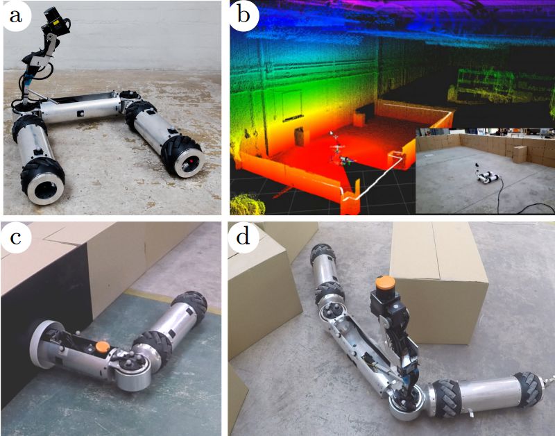
2

used for the controllability proofs in Section V, as well as
the feedback control used for trajectory tracking. Section VI
demonstrates omni-directional capability (controllability) for
non-standard Mecanum wheel configurations through a series
of experiments and ingress of 150 mm access port1 , as well
as limitations of the robot. Section VII details the deployment
of the robot in the Magnox facility in Sellafield and lessons
learned. Finally, Section VIII concludes the work and provides
an outlook to future work.
                                                                               Fig. 2. Mecanum wheel arangements (a) X-configuration (standard) (b) O-
                         II. R ELATED W ORKS                                   configuration (c) Straight line configuration.
   A comprehensive review of ground mobile robots used
in the nuclear industry is presented in [2]. Many of these
environments are highly cluttered due to machinery and there
are often areas which cannot be explored using traditional
platforms due to their size. This is further compounded by the
restriction on the access port for accessing such facilities to
150 mm diameter. With these restrictions in place, the choice
of using reconfigurable robots, though more complicated, can
address these difficult restrictions.

A. Reconfigurable Robots
                                                                               Fig. 3. (left) The main elements of the MIRRAX: body, legs, wheel and
   In a recent case study [4], Sarcos’ Guardian S re-                          joint assemblies (right) Arm assembly.
configurable robot was used to inspect a dust extraction
system, reducing both risk to employees and manufacturing
downtime. Another example was developed by Tokyo Electric                      lacks experimental validation for non-standard configurations;
Power Company (TEPCO) [3]. Their robot was designed to                         the experiments in [15] evaluated the X- (standard) and O-
take a tubular form, traverse a narrow pipe, and once clear of                 configuration (inverted standard) only.
the pipe expand into a U shape for stability.
   Other forms of mobile robotic platforms that fulfil the                                         III. H ARDWARE D ESIGN
access port requirement include modular re-configurable [5]
                                                                                  MIRRAX consists of a tubular body and two tubular legs,
and snake-type robots [6], [7], which typically have payloads
                                                                               with a pair of wheels connected to each leg and joints con-
that are small and light weight. In general, there has been little
                                                                               necting the legs to either end of the body section. Fig. 3 shows
attention given to developing robotic platforms that fulfil the
                                                                               the main components of MIRRAX while Table I summarises
access requirements and have the capability for large sensor
                                                                               the technical specification of the robot. The joint assemblies
payloads. Such robots are especially valuable for nuclear
                                                                               allow the legs to rotate about their connection to the main
environments, as seen by the case study from TEPCO.
                                                                               body through 190°in the x − y plane. The legs of MIRRAX
                                                                               house the robot’s electronics and the body section carries the
B. Controllability of Mecanum Wheels                                           sensor payload on a pan-tilt unit attached to a linear-actuated
   The use of Mecanum wheels in a re-configurable manner                       lever arm which can be raised or lowered. (see Fig. 3right).
deviates significantly from literature and commercial robots.                  The design of the arm enables a larger payload mass to be
Mecanum wheels are commonly arranged in a rectangular                          attached to its end compared to an articulated arm. Having
shape, where the rollers form an X-shape when viewed from                      the capability to raise and lower the arm serves two purposes.
above (see Fig. 2) [8], [9], [10]. The same arrangement is                     First, the overall height of the robot can be adjusted for
observed for platforms with more than four wheels [11]. More                   the 150 mm port ingress or overhanging obstacles. Secondly,
recently, Mecanum wheels arranged in a straight line have                      the direction and height of the sensor can be adjusted for
been proposed [12], [13]. Compared to ballbots [14] which                      improving the quality of data collected.
have a single contact point with the ground and are non-                          For robustness, MIRRAX’s body, legs, joints and wheel
holonomic, a straight line configuration with Mecanum wheels                   hubs are constructed from custom made aluminium parts. The
has a larger number of contact points and is holonomic.                        hollow Mecannum wheels are also custom made, using 3D
   With regards to the controllability of using Mecanum                        printed parts.
wheels, either arranged in a standard or non-standard shape,
this criteria has been evaluated using either the velocity                     A. Locomotion and Articulation
Jacobian [15], [16], linearised dynamics [17], or by heuristics,
using a line-crossing approach [18]. The literature in general                   MIRRAX’s Mecannum wheels run on bespoke hollow axle
                                                                               hubs, allowing space for the servo motors to sit inside the
  1A   video of the experiments is available at https://tinyurl.com/2kehf43z   wheels and for the wiring loom to run through the centre
3
TABLE I
G ENERAL SPECIFICATIONS OF THE MIRRAX ROBOT All computational components are housed in Leg 2. The
main computation unit is a single board PC running Linux
Description Value and ROS (Robot Operating System). All of the software for
External dimensions (L x W x H)
(U-configuration) 0.58 m x 0.51 m x 0.13 m MIRRAX is written in C++ and is deployed within the ROS
(Straight-line configuration) 0.140 m x 0.13 m x 0.13 m architecture. All software runs on the single board PC inside
Body + Arm 3.1 kg MIRRAX, any external connected computers are used for
Leg 1 0.7 kg
Weight Leg 2 0.8 kg sending simple messages such as position estimates, waypoints
Wheel (each) 1.15 kg or velocity commands if MIRRAX is under manual control.
Joint (each) 0.3 kg In addition to the single board PC, Leg 2 houses the servo
Total 9.8 kg
Payload size Up to 80 mm x 240 mm communication board, the actuator driver for the arm and
Payload weight Max 2kg the WiFi antennas. MIRRAX can connect to external control
Communication interface Wireless or tethered computers using either WiFi or Ethernet via a tether.
Battery/run-time 2 hours
Maximum velocity 0.78 m/s The body element of MIRRAX is used to store the sensor
payload, this will include both sensors for navigation and any
sensors that will be used for surveying or monitoring tasks.
Sensors in the body element are attached to an articulated
arm that rises vertically from the body section.The default
sensor package is a rotating LiDAR for navigation and 3D
reconstruction paired with a collimated cadmium zinc telluride
(CZT) gamma-ray and x-ray detector.
IV. ROBOT M ODELLING AND C ONTROL
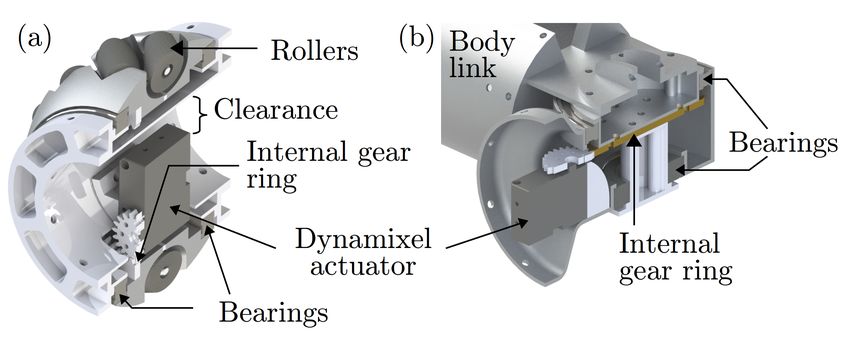
Fig. 4. Sectional view of (a) wheel, and (b) joint assembly. The kinematic and dynamic model of a mobile robot
with Mecanum wheels is well established in the literature
and is included here for completeness [19], [16], [15], [18],
of the robot (see Fig. 4a). The wheels are connected to the [17].hWith reference to Fig. 6, the full state
i of the robot is
T
hub via thin profile sealed roller bearings. MIRRAX’s wheels q̇ = ẋ, ẏ, θ̇, φ̇1 , φ̇2 , ω1 , ..., ωnw , ϕ̇1 , ..., ϕ̇nw . The first three
are driven by velocity controlled servo motors with toothed terms are the base velocity at fb expressed in the inertial frame,
gears attached to their horns. The toothed gear drives an followed by the angular velocity of the leg joints φ̇1,2 , and
internal ring gear that is fixed to the inner radius of the wheel finally the wheel ω and roller ϕ̇ angular velocities respectively,
with a 3:1 reduction ratio. The maximum linear velocity of where nw is the number of wheels of the robot, in this case
MIRRAX is 0.78 m/s2 ; this limit is a result of the maximum nw = 4. The fictitious frame, fr , corresponds to the robot’s
velocity of the Dynamixel XM430-350T servo motors used, geometrical centre between the wheels. A more compact form
and the requirement for hollow wheels leading to the use of a
ring gear. Despite the low maximum velocity, these particular
servo motors were selected for their size, power consumption,
reliability and ease of integration.
The joints of MIRRAX are actuated in a similar way, using
matching servo motors and an internal ring gear (see Fig. 4b).
The key difference is that the servo motors in the joints are
operated in position control mode rather than velocity control
to enable the joint angles to be regulated. The gearing ratio
between the Servo motor and the joint is also 3:1.
B. Electronics Architecture
Fig. 5 shows a schematic of the layout of, and interconnec-
tions between, the electronic components inside MIRRAX. A
description of the electronic architecture follows.
MIRRAX is powered by a 4 Ah 11.1 V lithium polymer
battery housed in Leg 1. At full charge, the battery capacity
enables the robot to be operated for approximately 2 hours.
Alternatively, the robot can be operated indefinitely using
a tether for both power and communication. Alongside the
battery, Leg 1 houses the power board for the servo motors, Fig. 5. Schematic showing the system architecture of MIRRAX’s electronic
on/off switches and the charging port. components.
4

for the
     h reduced generalisediT state for the robot is expressed as            where êz ∈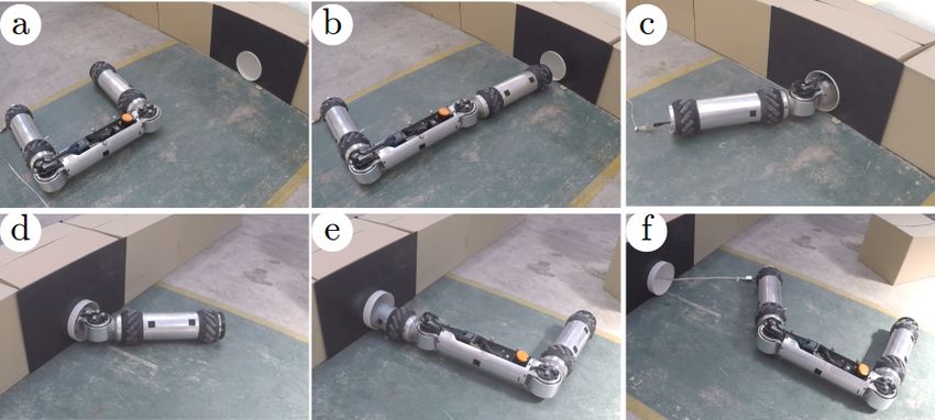
5

use the position vector from the robot frame,fr , to the wheel     C. Control System
frame instead of pbi . This vector can be easily calculated once     To enable trajectory tracking, a PD feedback controller was
the vector from fr to fb is determined as follows,                 employed for the robot’s base velocity. The controller velocity
                                P
                                    pbi                            output, vcmd , for a desired position, pd and velocity, ṗd , is
                         pbr =          .                   (13)   described by the control law
                                   4
   The forward kinematics for calculating the robot’s base                   vcmd = ṗd + Kp (pd − p) + Kd (ṗd − ṗ)           (18)
velocity given the wheel and leg joint velocities is described     where Kp and Kd are diagonal gain matrices.
by                                                                    The resulting ω from vcmd in (18) may not be within
                                        " #!

                     −1
                         +
                                     −1   q̇5                      the actuator limits. It is not possible to directly impose
             ζb = Jw,L        ω − Jw,R                    (14)     fixed velocity limits on vcmd since the velocity limits are
                                          q̇6
                                                                   configuration dependant. Furthermore, it is desirable for the
where ()+ is the Moore-Penrose Pseudoinverse, ω ∈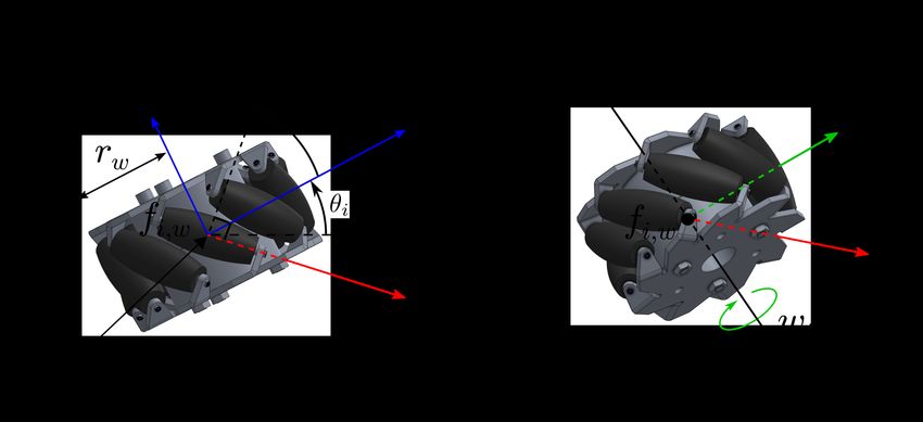
6

   Fig. 8 shows the GSI and the determinant from (20) and                  here, namely by evaluating the Kalman controllability matrix
(23) for the full range of joint configurations for MIRRAX.                (KCM) using the linearised system dynamics.
The plots Fig. 8a-b shows the maximum while Fig. 8c-d shows                   For the state vector, X = (p, ṗ)T , the resulting linearisation
the minimum GSI and determinant respectively. The maximum                  takes the form Ẋ = AX + Bu, where
and minimum determinant for a particular configuration was                          "              #      "      #
                                                                                      05×5 , I5×5           05×5
determined among the possible wheel combinations, i.e.                        A=                     , B = ∂D , u = [τ1 , ..., τ4 ]T (27)
                                                                                      05×5 , ∂D
                                                                                              ∂ ẋ           ∂u
                  dmin = min(dc1 , dc2 , dc3 , dc4 )               (25)
                 dmax = max(dc1 , dc2 , dc3 , dc4 )                (26)    and D is the forward dynamics from (17).
                                                                              The linearisation point was evaluated across the full range
where c1 to c4 correspond to wheels in contact in the following            of φ1 and φ2 , similar to Section V-A since these two joints
combination (1,2,3), (1,2,4), (1,3,4) and (2,3,4) respectively.            can have an impact on the controllability. Stepping through the
The GSI approach differs slightly in evaluating (25) with the              various joint angle combinations at 5° intervals and evaluating
addition of the wheel combination c5, where all the wheels                 the KCM of (27) resulted in full rank Kalman Controllability
are in contact.                                                            Matrix (KCM) for all the configurations evaluated. Hence, the
                                                                           robot is controllable for all configurations.

                                                                               VI. E XPERIMENTAL E VALUATION AND D ISCUSSION
                                                                              This section presents experimental validation of the robot
                                                                           in achieving (a) ingress and egress through 150 mm diameter
                                                                           access ports, and (b) controlled navigation of confined areas.
                                                                           A video showing the experiments is available.

                                                                           A. Experimental Set Up
                                                                              Manual control of the robot’s base velocity follows a simple
                                                                           mapping from a PS4 joystick to (ẋ, ẏ, φ̇); similar to ROS 2D
                                                                           twist commands. Additional velocity commands and function-
                                                                           alities were introduced to actuate the legs and arms (integrating
                                                                           the velocity commands for the legs and arm positions) using
Fig. 8. Controllability of MIRRAX for different configurations evaluated   the buttons available on the PS4 joystick.
using the determinant approach (top), and the GSI approach (bottom).
                                                                              For trajectory tracking, a 5D trajectory [x, y, θ, φ1 , φ2 ]
                                                                           has been generated using an adapted version of the ROS
   It can be observed from all four plots in Fig. 8 that the               mav trajectory generation2 package. Feasibility of the trajec-
robot’s controllability is symmetrical about the top-left to               tory generated against the wheel velocity limit is checked in an
bottom-right diagonal axis. This indicates symmetrical rela-               exhaustive manner using (12). In the event that the trajectory
tionship for configurations about the robot’s lateral axis, e.g.           violates the wheel velocity limits, the trajectory is scaled in
for an arbitrary leg joint angle φa and φb , the controllability           time by the ratio s = ω/ωmax + 0.05 and the feasibility check
is the same, nc (φa , φb ) = nc (φb , φa ).                                is repeated until it becomes feasible. A VICON system is used
   Comparing between Fig. 8a-b and Fig. 8c-d, it can be seen               for both ground truth and the feedback controller, which runs
that the controllability is dependant on the wheels having                 at 100 Hz.
ground contact. Under the ideal condition where all the wheels
are in contact, the robot is controllable for all joint configura-
tions since both the determinant and GSI are non-zero (Fig. 8a-            B. Limited Access Entry
b). Both these metrics approach zero as |φ1,2 | →     − 180, the              The primary hardware requirement is for the robot to ingress
inverted-U shape, implying an increase in susceptibility to                and egress 150 mm diameter access ports. A snapshot of this
disturbance and being less controllable i.e. taking longer to              motion is shown in Fig. 9. The robot was first re-configured to
reach a desired state. However, the possible loss in wheel                 a L-shape configuration (Fig. 9b), then driven down the access
ground contact for extended periods of time can render the                 port. As the rear leg approaches the port, it was moved to
robot uncontrollable as seen by the dark blue regions in                   φ1 = 90° (Fig. 9c). At the same time, the front leg which has
Fig. 8c-d where the determinant and GSI are zero.                          emerged from the port was moved towards its default position
                                                                           as much as possible without colliding with the wall (Fig. 9d).
B. Linearised Dynamics                                                     As the robot continues moving and exits the port completely,
                                                                           the rear leg takes back its default position since the exit area
   The global controllability for a non-linear system, as is the           had sufficient clearance.
case in this study, does not exist as compared to a linear                    A scenario that may occur inside or on exiting the port is
system. A weaker form of this proof is to instead show that                for the robot to roll around its x-axis. In its current state, it is
it is small-time locally controllable (STLC), as shown in [17]
for a collinear mecanum drive. A similar approach is used                    2 https://github.com/ethz-asl/mav   trajectory generation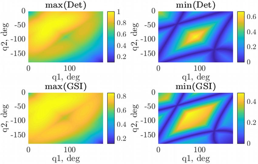
7

Fig. 9.   Ingress and egress from a 150 mm diameter access port.

                                                                                Fig. 11. Trajectory tracking at non-standard a configuration (a) (45,-45) in
                                                                                open-loop and close-loop with and without counter-mass. (b) (45,-45) and
possible to orientate the robot to be right-side up (θroll = 0°)                (45,-135) close-loop without counter-mass.
if −90° / θroll / 90°. The robot becomes unable to orientate
itself beyond this range due to the placement of components
which results in mass imbalance. As such, the counter-torque                    available inside the leg links, and the end of the leg having
from the wheels is unable to rotate the robot’s base back up.                   the largest distance from the robot’s geometrical centre i.e.
                                                                                a larger moment arm reduces the mass required. The total
C. Mass Balance                                                                 mass required for the robot’s CoM to be coincident with the
   The inherent design of MIRRAX, having both the front                         geometrical centre was calculated to be 5.44 kg, or 2.72 kg per
and rear leg connected via a link that does not pass through                    leg. For the maximum arm payload of 2 kg, a counter-balance
the centre of the robot, results in an off-balance Centre-of-                   mass of 4.24 kg per leg was required.
Mass (CoM). The robot’s CoM is not fixed due to the robot’s                        The result of having the mass balance is shown in both
reconfigurable capability, thus depending on both the legs and                  Fig. 10 and 11(left) with the legend weighted where significant
arm position. Taking the U-shape (default) configuration as                     improvement is observed on both open- and close- loop
a starting point, the robot’s CoM can be calculated from                        tracking of the desired path. However, the overall mass of
the mass of the individual links, summarised in Table I.                        the robot is increased significantly, where the counter-mass
The CoM lateral offset is found to be located to the right                      accounts for 36 % of the final mass. A possible strategy to
of its geometrical centre, while the longitudinal offset is                     circumvent or reduce the use of counter-mass used is to utilise
approximately coincident.                                                       a Z-configuration, as seen by the imposed image of MIRRAX
   Offset in the robot’s CoM has the undesirable effect of                      in Fig. 11(right). This configuration indirectly balances the
reducing surface traction on one or more wheels, causing                        mass of the robot, resulting in the CoM to be coincident with
the robot to deviate from the desired motion, as shown                          its geometrical centre provided the mass of both leg is similar.
by the non-symmetrical motion of clockwise and counter-                         The resulting trajectory tracking performance using the Z-
clockwise motion in Fig. 10 for the default configuration                       configuration is comparable with the weighted approach.
(φ1 = φ2 = 0°) [21]. The problem becomes more evident                              Although close-loop does indeed improve the performance
at other configurations, e.g. at φ1 = −φ2 = 45° where the                       especially when operated without the counter-mass, there are
robot becomes incapable of straight line motion since both                      advantages when the open-loop tracks the desired path such as
the left most wheels lost a sufficient amount of traction, as                   ease of control in manual mode and lower power consumption
shown in Fig. 11a (Unweighted + open-loop).                                     as since it drifts less. Furthermore, higher accuracy can be
                                                                                obtained from odometry localization as well. It should be
                                                                                noted that the balancing mass used in this experiment was tem-
                                                                                porary since the mass required depends on the sensor payload
                                                                                on the arm, which in turn depends on the mission/research
                                                                                requirement. Hence the counter-mass was left as an ad-hoc
                                                                                solution here and will be modified in the future accordingly.

                                                                                D. Robot Balance
                                                                                   As the robot approaches the straight-line configuration
                                                                                (φ1 = −φ2 = 90°), it becomes dynamically unstable and
                                                                                susceptible to rolling over. Although it was possible to employ
Fig. 10. Trajectory tracking of a square at (0,-0) configuration in open-loop   controllers capable of both balancing and moving the robot
and close-loop with and without counter-mass (a) counter-clockwise and (b)
clockwise rotation.                                                             at this configuration [17], the decision was taken to avoid
                                                                                this configuration during operation, except for the ingress and
   To counter-balance this, additional mass was attached to                     egress from the access port. This was due to the risk of rolling
the end of the leg links. This is due to the limited space                      over during operation, which can cause the robot to be unable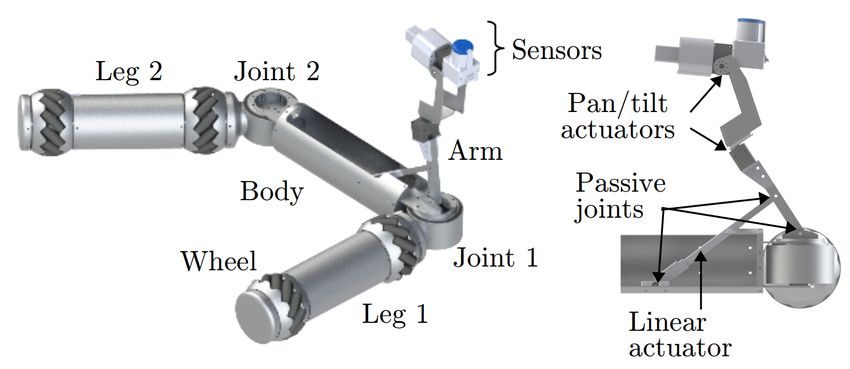
8

                                                                                                           TABLE II
to right itself as discussed in Section VI-B, and from crashing,                   Q UANTITATIVE ASSESSMENT OF DIFFERENT CONFIGURATIONS FOR
which can have detrimental effect on the sensors located on                                        MINIMUM STABLE FOOTPRINT.
the arm.
                                                                                      Configuration       Width, m     Max (Roll), °   σ, °   ATE, m
   A selected number of configurations were evaluated to char-                        (85,-85)            0.15         13.79           3.35   0.27
acterise the minimum stable footprint using the robot’s roll and                      (80,-80)            0.19         4.82            0.84   0.17
absolute trajectory error (ATE) as quantitative measures. The                         (75,-75)            0.22         2.46            0.54   0.26
                                                                                      (70,-70)            0.26         1.96            0.44   0.12
configurations explored were generally based on a trapezoidal                         (85,-95)            0.14         22.53           6.99   0.34
and Z- shape (see Fig. 12): the first when both |φ1,2 | < 90°                         (80,-100)           0.16         15.08           2.35   0.32
(trapezoidal), the second when φ1 < 90° and φ2 < −90°                                 (75,-105)           0.17         5.68            1.20   0.22
                                                                                      (70,-110)           0.19         3.42            1.05   0.11
(zig-zag).                                                                            (65,-115)           0.21         3.74            0.69   0.13
                                                                                      (75,-115)           0.19         1.93            0.69   0.16
                                                                                      (70,-120)           0.21         1.85            0.57   0.16

                                                                                motion would result in rolling both due to gravity and from
                                                                                the actuators’ counter-torque.
                                                                                   The roll and ATE reduced significantly for the subsequent
Fig. 12. General configurations for minimum stable footprint (a) trapezoidal
(b) Z- shape.                                                                   configurations, with the largest improvement observed at (80,-
                                                                                80) and (75,-105). For the remaining configurations, only
   Fig. 13(top) shows the roll angle from executing a mo-                       slight improvements in the reduction of roll was observed,
tion where the orientation of the robot and inertial frames                     although the Z-shape gained a larger improvement in tracking
were fixed and aligned, while the direction of motion was                       with a smaller ATE, ≤ 0.13 m. The (75,-75) configuration had
not aligned to the body frame x-axis (see Fig. 13(bottom)).                     a larger ATE error due to significant wheel slippage observed
Table II summarises the result for the different configurations                 during the motion. It was expected that the ATE would fall
evaluated.                                                                      between 0.17 m and 0.12 m under no slip conditions.
                                                                                   The Z-shape configurations does not result in better perfor-
                                                                                mance compared to the trapezoidal shape at footprint width
                                                                                of less than 0.19 m. However the performance changed as the
                                                                                width increased, where the Z-shape achieved better tracking
                                                                                and less roll compared to its counterpart. The minimum 90°
                                                                                corner path width that MIRRAX can fit through was approxi-
                                                                                mately 0.3 m (horizontal width). Assuming that the path lead-
                                                                                ing up to the corner is of a similar size, the configurations (75,-
                                                                                115) and (70,-120) would yield a better choice. This selection
                                                                                provides larger wall clearance and similar quantitative metric
                                                                                compared to the (70,-70) configuration.
                                                                                   An interesting observation on the minimum footprint exper-
                                                                                iments was that the robot was sometimes unable to progress
                                                                                along the desired trajectory due to wheel slippage. This
                                                                                scenario was observed to occur at a similar area for the
                                                                                different experiments carried out (see Fig. 13(bottom) for the
                                                                                stuck region). Increasing the controller gains and leaving it
                                                                                to continue attempting to reach the goal position3 failed with
                                                                                it remaining in the same spot. Whilst not shown here, the
                                                                                robot was made to escape this slippage by inducing motions
                                                                                in other directions e.g. sideways then forward instead of a pure
                                                                                diagonal motion. This scenario highlights the susceptibility of
                                                                                being stuck due to wheel slippage, similar to other types of
                                                                                wheeled robots. However, the capability for omni-directional
                                                                                motion in this case allows for additional motions to be used
Fig. 13. (top) Magnitude of base roll at various configurations for assessing
minimum stable footprint. (bottom) Trajectory tracking at various configura-    to escape from being stuck.
tion experiencing wheel slippage at a similar spot.

                                                                                E. Controllability
   It can be observed from Fig. 13(top) and Table II that both                     Using the proofs presented in Section V, the robot was
the magnitude of the undesirable roll and ATE was especially                    theoretically controllable over its full range of motion. The
significant near the straight line configuration: (85,-85) and                  practicality of this was evaluated on a number of experiments.
(85,-95). This was due to these two configurations being close
to a dynamically unstable configuration, whereby any form of                      3 The   start and goal position is the same.
9

Fig. 14 shows the robot tracking a pre-defined trajectory with                  in March 2018. The deployment area was part of the Magnox
either fixed- or dynamic leg configurations. Fig. 14a shows a                   reprocessing facility which had been sealed for a number
representation of omni-directional motions. Fig. 14b shows the                  of years and was the first time a mobile robot had been
robot navigating through a narrow path. In general, the robot                   deployed into this facility. The purpose of the deployment was
was able to track the prescribed trajectory closely, where the                  to geometrically characterise the area so that decommissioning
error magnitude for the xy-position and orientation was less                    plans could be generated. A video of the deployment is
than 0.018 m and 0.6° at any time instant for both motions.                     available4 .
                                                                                   The robot used in the deployment was largely similar in de-
                                                                                sign with minor differences: the robot’s links were constructed
                                                                                from PVC and 3D printed parts and the arm consisted of an
                                                                                actuated articulated joint with a pan unit. The CoM for the
                                                                                robot used in the deployment was closer to its geometrical
                                                                                centre due to the materials used being lighter. The mass of
                                                                                the wheels was larger than the rest of the links, enabling self-
                                                                                righting from arbitrary roll angles.
                                                                                   The arm design differed from the robot presented earlier
                                                                                in Section III since the payload used in the deployment was
                                                                                lighter. The sensor payload consisted of two 2D LIDARs
                                                                                attached to a pan unit, enabling 3D mapping while still being
                                                                                able to localise using the forward facing LIDAR. An RGB
                                                                                camera located at the edge of the front leg enabled visual
                                                                                feedback for the operator.
                                                                                   The robot was tethered and operated manually, with the
Fig. 14.   Trajectory tracking with (a) fixed (b) dynamic leg configurations.
                                                                                tether being used for both power and communication to the
                                                                                base PC. An RGB camera enabled a coloured view of the
   The robot was further evaluated by attempting to navigate
                                                                                facility (see Fig. 16a-b). Inside the facility, the robot utilised
through cluttered and confined environments via manual con-
                                                                                its forward-facing LIDAR for 2D SLAM as it was driven
trol mode. Fig. 15 shows a snapshot of the robot’s motion
                                                                                forward for inspection and mapping. After travelling for short
navigating through a 90° corner accessible only through nar-
                                                                                intervals, the robot was stopped and the pan unit was rotated
row pathway. Control of the robot without the counter-mass
                                                                                to increase point cloud data collection from the top-facing
was possible and was generally responsive as seen in Fig. 15
                                                                                LIDAR. The point cloud collected was post-processed offline,
and the supplementary video.
                                                                                the final render of the facility is shown in Fig. 16c.

Fig. 15. Manual control demonstration of navigating cluttered and confined
environments.

   There were instances where the wheel lost traction due to
the mass balancing issue discussed previously in Section VI-C.
This was observed while navigating the corner which required
the robot to take on a configuration close to (45,-45) which was
known to cause loss of controllability. However, by perturbing
the robot’s motion and adjusting the legs it was possible to
navigate through the corner. The Z-shape was also used where                    Fig. 16. (a) MIRRAX inside the Magnox facility. (b) RGB camera view (c)
possible to minimise the robot’s roll.                                          rendered 3D point cloud of facility.

                                                                                   At the end of the mapping session, the LIDAR units were
                 VII. S ELLAFIELD D EPLOYMENT
                                                                                retrieved and the rest of the robot was disposed as low-
  A version of the MIRRAX robot was deployed into a real-
world, low-level radioactive facility on the Sellafield site, UK                  4 Deployment   video: https://tinyurl.com/mvewxx9w
10

level radioactive waste. The overall deployment sucessfully                    [8] J. A. Cooney, W. L. Xu, and G. Bright, “Visual dead-reckoning for
proved the feasibility of both MIRRAX and in general, mobile                       motion control of a Mecanum-wheeled mobile robot,” Mechatronics,
                                                                                   2004.
robotic platforms, being used for remote inspections in these                  [9] R. Bischoff, U. Huggenberger, and E. Prassler, “KUKA youBot - A
hazardous environments.                                                            mobile manipulator for research and education,” in IEEE International
                                                                                   Conference on Robotics and Automation, 2011.
                                                                              [10] J. S. Keek, S. L. Loh, and S. H. Chong, “Comprehensive Development
                        VIII. C ONCLUSIONS                                         and Control of a Path-Trackable Mecanum-Wheeled Robot,” IEEE
   This paper has presented MIRRAX, a reconfigurable robot                         Access, vol. 7, pp. 18 368–18 381, 2019.
                                                                              [11] KUKA AG, “KUKA omniMove,” 2021. [Online]. Avail-
driven by Mecanum wheels. Special focus has been given to                          able: https://www.kuka.com/en-gb/products/mobility/mobile-platforms/
its design to enable it to have sufficient payload capability                      kuka-omnimove
as well as fit through a 150 mm diameter access port. The                     [12] S. Reynolds-haertle and M. Stilman, “Design and Development of
                                                                                   a Dynamically-Balancing Holonomic Robot,” IEEE Transactions on
incorporation of a feedback controller was shown to enable                         Industrial Electronics, pp. 1–6, 2011.
trajectory tracking for arbitrary leg configurations. Preliminary             [13] M. T. Watson, D. T. Gladwin, T. J. Prescott, and S. O. Conran, “Design
experiments confirmed the robot’s capability for 150 mm                            and control of a novel omnidirectional dynamically balancing platform
                                                                                   for remote inspection of confined and cluttered environments,” Proceed-
diameter access port entry and omni-directional capability.                        ings - 2018 IEEE International Conference on Industrial Electronics for
The validation experiments also highlighted certain limitations,                   Sustainable Energy Systems, IESES 2018, vol. 2018-Janua, pp. 473–478,
such as the off-balance CoM, wheel slippage, and rolling and                       2018.
                                                                              [14] T. Lauwers, G. Kantor, and R. Hollis, “One is enough!” Springer Tracts
recovery when MIRRAX was in a straight-line configuration.                         in Advanced Robotics, 2007.
The robot was subsequently deployed in the Magnox facility                    [15] C. He, D. Wu, K. Chen, F. Liu, and N. Fan, “Analysis of the Mecanum
on the Sellafield site, showcasing the relevance of the robot                      wheel arrangement of an omnidirectional vehicle,” Proceedings of the
                                                                                   Institution of Mechanical Engineers, Part C: Journal of Mechanical
in practical scenarios and providing valuable insight of the                       Engineering Science, vol. 233, no. 15, pp. 5329–5340, 2019.
facility for the site operators.                                              [16] A. V. Borisov, A. A. Kilin, and I. S. Mamaev, “Dynamics and control of
   The outlook for the hardware development includes inte-                         an omniwheel vehicle,” Regular and Chaotic Dynamics, vol. 20, no. 2,
                                                                                   pp. 153–172, 2015.
grating sensors for environment and radiation mapping, along                  [17] M. T. Watson, D. T. Gladwin, and T. J. Prescott, “Collinear Mecanum
with control system and hardware modifications to deal with                        Drive: Modeling, Analysis, Partial Feedback Linearization, and Nonlin-
the robot’s mass balance. Addressing the mass balance by                           ear Control,” IEEE Transactions on Robotics, pp. 1–17, 2020.
                                                                              [18] Y. Li, S. Dai, L. Zhao, X. Yan, and Y. Shi, “Topological design methods
hardware can potentially address the rolling recovery limita-                      for mecanum wheel configurations of an omnidirectional mobile robot,”
tion and the off-balance CoM observed in the experiments.                          Symmetry, vol. 11, no. 10, 2019.
However, this would introduce additional mass thus reducing                   [19] J. Agulló, S. Cardona, and J. Vivancos, “Kinematics of vehicles with
                                                                                   directional sliding wheels,” Mechanism and Machine Theory, vol. 22,
the operational time of the robot. Alternatively, addressing the                   no. 4, pp. 295–301, 1987.
balance using the control system, for example moving with                     [20] X. J. Liu, Z. L. Jin, and F. Gao, “Optimum design of 3-DOF spherical
the Z-shape, removes the need for introducing additional mass.                     parallel manipulators with respect to the conditioning and stiffness
                                                                                   indices,” Mechanism and Machine Theory, vol. 35, no. 9, pp. 1257–
However, this is limited to scenarios where it is possible to take                 1267, 2000.
on the Z-shape, which may not always be possible, especially                  [21] J. Borenstein and L. Feng, “UMBmark: A Benchmark Test for Measur-
when navigating cluttered environments. A combination of                           ing Odometry Errors in Mobile Robots,” in SPIE Conference on Mobile
                                                                                   Robots, 1995, pp. 1–12.
both approaches could yield a more satisfactory solution.
   Future work on motion planning will involve adapting
existing motion planers, such as sampling-based methods, for
use on MIRRAX with constraints introduced to avoid near
straight-line configurations and selecting z-shape especially for
narrow pathways. The final goal is to develop the methodology
to achieve full autonomy for MIRRAX.

                             R EFERENCES
 [1] F. Zhao, Y. Ma, and Y. Sun, “Application and Standardization Trend of
     Maintenance and Inspection Robot (MIR) in Nuclear Power Station,”
     DEStech Transactions on Engineering and Technology Research, 2017.
 [2] I. Tsitsimpelis, C. J. Taylor, B. Lennox, and M. J. Joyce, “A review
     of ground-based robotic systems for the characterization of nuclear
     environments,” Progress in Nuclear Energy, vol. 111, pp. 109–124,
     2019.
 [3] Tepco, “Application of Robot Technology,” 2017. [Online]. Available:
     https://www.tepco.co.jp/en/decommision/principles/robot/index-e.html
 [4] Sarcos, “Guardian S Case Study: General Electric (GE).” [Online].
     Available: https://www.sarcos.com/products/guardian-s/case-study/ge/
 [5] J. Seo, J. Paik, and M. Yim, “Modular Reconfigurable Robotics,” Annual
     Review of Control, Robotics, and Autonomous Systems, 2019.
 [6] S. Hirose and H. Yamada, “Snake-like robots: Machine design of
     biologically inspired robots,” IEEE Robotics and Automation Magazine,
     2009.
 [7] F. Trebuňa, I. Virgala, M. Pástor, T. Lipták, and L. Miková, “An
     inspection of pipe by snake robot,” International Journal of Advanced
     Robotic Systems, vol. 13, no. 5, p. 1729881416663668, 2016.
You can also read