Modification of Paper into Conductive Substrate for Electronic Functions - Elson Montibon Deposition, Characterization and Demonstration
←
→
Page content transcription
If your browser does not render page correctly, please read the page content below
Faculty of Technology and Science
                   Chemical Engineering

                Elson Montibon

  Modification of Paper
into Conductive Substrate
 for Electronic Functions

Deposition, Characterization and Demonstration

                 DISSERTATION
             Karlstad University Studies
                         2010:28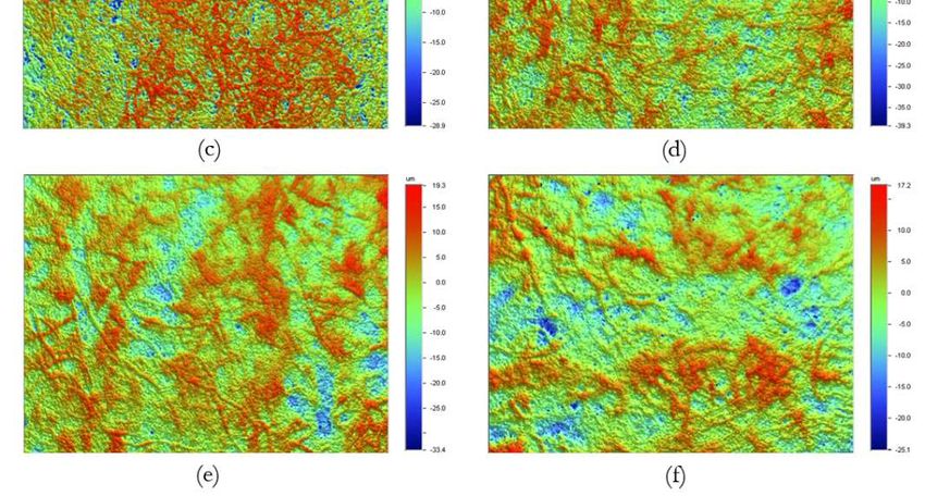
Elson Montibon

  Modification of Paper
into Conductive Substrate
 for Electronic Functions

Deposition, Characterization and Demonstration

             Karlstad University Studies
                       2010:28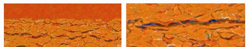
Elson Montibon.
Modification of Paper into Conductive Substrate for Electronic Functions
- Deposition, Characterization and Demonstration

Dissertation

Karlstad University Studies 2010:28
ISSN 1403-8099
ISBN 978-91-7063-361-4

© The Author

Distribution:
Karlstad University
Faculty of Technology and Science
Chemical Engineering
S-651 88 Karlstad
Sweden
+45 54 700 100

www.kau.se

Print: Universitetstryckeriet, Karlstad 2011
“Delight thyself also in the LORD: and
he shall give thee the desires of thine
heart.”
                              Psalm 37:4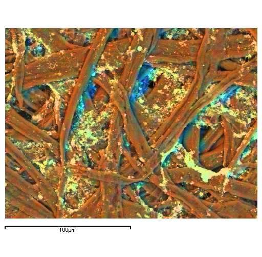
Abstract

The thesis investigates the modification of paper into an ion- and electron-conductive
material, and as a renewable material for electronic devices. The study stretches from
investigating the interaction between cellulosic materials and a conducting polymer to
demonstrating the performance of the conductive paper by printing an electronic structure
on the surface of the conductive paper. Conducting materials such as conducting polymer,
ionic liquids, and multi-wall carbon nanotubes were deposited into the fiber networks.

In order to investigate the interaction between the conducting polymer and cellulosic
material, the adsorption of the conducting polymer poly(3,4-ethylenedioxythiophene):
poly(4-styrene sulfonate) (PEDOT:PSS) onto microcrystalline cellulose (MCC) was
performed. The adsorption isotherm showed a broad molecular distribution of the
conducting polymer and considerable interaction between the polymer and the MCC. The
amount adsorbed decreased with increasing pH of the dispersion and varying the salt
concentration of the solution revealed that the adsorption passed through a maximum.

Papers displaying electroconductive behavior were produced via dip coating and rod coating,
and characterized. The Scanning Electron Microscopy (SEM) / Energy Dispersive
Spectroscopy (EDS) images showed that the conducting polymer was deposited in the fiber
and in fiber-fiber contact areas. The X-ray Photoelectron Spectroscopy (XPS) analysis of
dip-coated paper samples showed PEDOT enrichment on the surface. The degree of
washing of the dip-coated paper with dilute acid did not significantly affect the PEDOT
enrichment on the surface. When the base paper was coated with a PEDOT:PSS blend, the
conductivity increased by many orders of magnitude. The base papers normally had bulk
conductivities in the region of 10-12 S/cm, and after modification, the conductivity reached
between 10-3 and 10-1 S/cm. The effects of fiber beating and paper formation were also
investigated. The presence of organic solvents N-methyl-2-pyrrolidone (NMP) and dimethyl
sulfoxide (DMSO) in the PEDOT:PSS dispersion enhanced the conductivity of the coated
sheets, while sorbitol and isopropanol had no enhancement effect. This is due to the
conformational changes of the PEDOT molecule in the presence of NMP and DMSO and
to their plasticizing effect. The conductivity of paper did not increase until the line load
reached 174 kN/m during calendering which is indicative of PEDOT:PSS being suspended
in the fiber network. The effect of the presence of pigments such as titanium dioxide (TiO2)
and multi-wall carbon nanotubes (MWCNT) was also discussed, and also their effects on
other properties such as tensile strength, surface property and wetting were discussed.

                                             i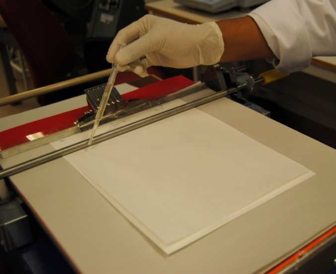
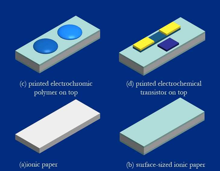
Ionic paper was produced by depositing an ionic liquid into the commercial base paper. The
effect of humidity on the ionic conductivity was determined. Even at a humidity as low as
25% RH, the ionic paper demonstrated good ionic conductivity. The temperature-
dependence of the ionic conductivity followed the simple Arrhenius equation, which can be
attributed to the hopping of carrier ions. The ionic paper was surface-sized in order to
reduce the roughness and improve its printability. The bulk resistance increased with
increasing surface sizing. The electrochemical performance of the ionic paper was confirmed
by printing PEDOT:PSS on the surface. There was change in color of the polymer when a
voltage was applied. It was demonstrated that the ionic paper is a good ionic conductor that
can be used as a component for a more compact electronic device construction.

Conductive paper has a great potential to be a flexible platform on which an electronic
structure can be constructed. The conduction process in the modified paper is due to the
density of charge carriers (ions and electrons), and their short range mobility in the material.
The charge carrying is believed to be heterogeneous, involving many species as the paper
material is chemically heterogeneous. Paper is a versatile material. Its bulk and surface
properties can easily be tuned to a desired level by modifying the fibers, adding chemical
additives, and surface treatment. Furthermore, the abundance of cellulosic material on this
planet makes conductive paper a renewable and sustainable component for electronic
devices.

                                               ii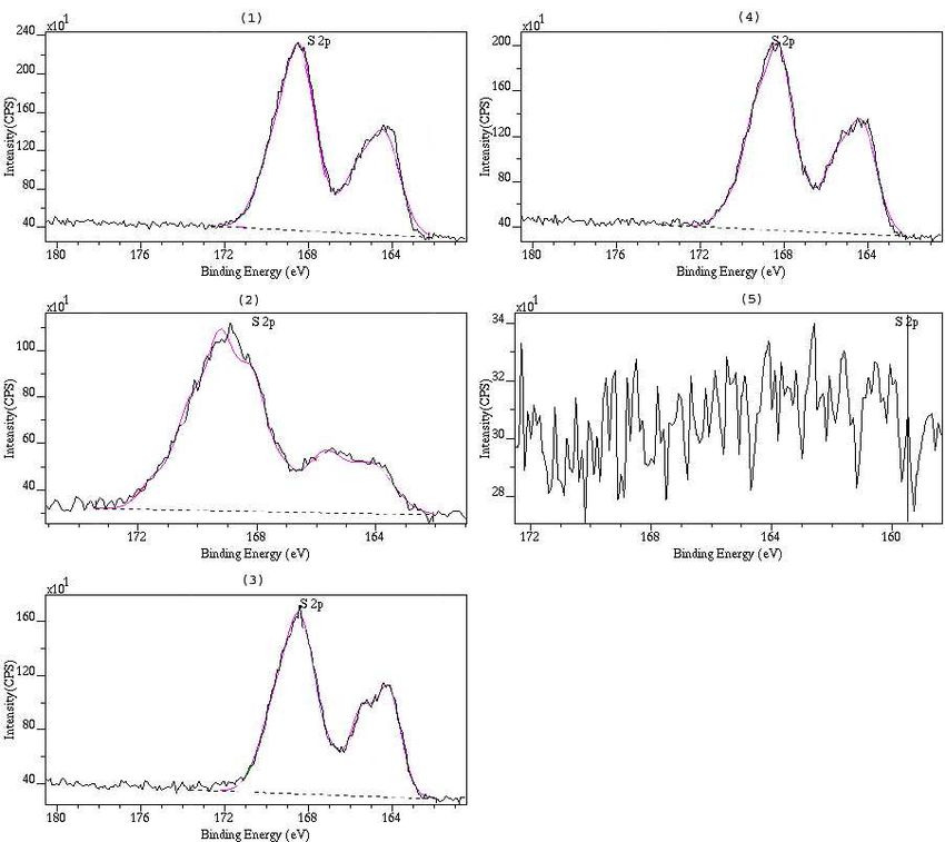
List of Papers

I      Characterization of Poly(3,4.ethylenedioxythiophene):Poly(4-styrenesulfonate)
       (PEDOT:PSS) on Cellulosic Materials
       Elson Montibon, Lars Järnström, and Magnus Lestelius
       Cellulose 2009, 16, 807-815

II     Electroconductive Paper Prepared by Coating with Blends of Poly(3,4-
       ethylenedioxythiophene)/Poly(4-styrenesulfonate)        (PEDOT:PSS) and
       Organic Solvents
       Elson Montibon, Magnus Lestelius, and Lars Järnström
       Journal of Applied Polymer Science 2010, 117, 3524-3532

III.   Electroconductive Paper – a study of conductivity achieved through polymer
       deposition and papermaking properties
       Elson Montibon, Karen T. Love, Magnus Lestelius, and Lars Järnström
       Nordic Pulp and Paper Research Journal 2010, 25 (4), 473-480

IV     Conductivity of paper containing poly(3,4-ethylenedioxythiophene)/poly(4-
       styrenesulfonate) and multi-wall carbon nanotubes
       Elson Montibon, Magnus Lestelius, and Lars Järnström
       Submitted for publication in Journal of Applied Polymer Science

V      Porous and Flexible Ionic Paper as a platform for compact electronic devices
       Elson Montibon, Magnus Lestelius and Lars Järnström
       Manuscript to be submitted for publication

Reprints of Papers I, II, and III have been made with permission from the publishers

Elson Montibon’s contribution to the papers
Elson Montibon performed all the experimental work with the exception of XPS in Paper I;
BET area in Papers I and II; SEM/EDS in Papers II, III and IV; and Hg-porosimetry in
Paper III. Elson is the main author of all five papers included in this thesis.

                                             iii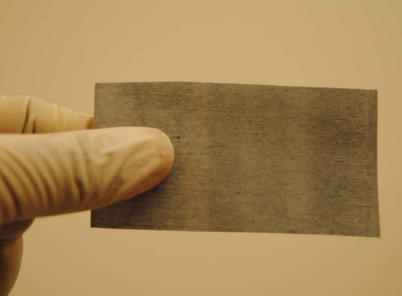
Related presentations by the same author

Montibon E., Järnström L., and Lestelius M., “On Investigation of
    Poly(3,4.ethylenedioxythiophene)/Poly(4-styrenesulfonate) (PEDOT:PSS) Adsorption
    on Cellulosic Materials”, Poster Presentation, Conference Proceeding of the Nordic
    Polymer Days 2008, Stockholm, Sweden, June 11-13, 2008.

Montibon E., Järnström L., and Lestelius M., “Characterization of Poly(3,4-
    ethylenedioxythiophene)/Poly(4-styrenesulfonate) (PEDOT:PSS) Adsorption on
    Cellulosic Materials”, Oral Presentation, Conference Proceeding of 13th IACIS
    International Conference on Surface and Colloid Science, and the 83rd ACS Colloid &
    Surface Science Symposium, Columbia University, New York City, USA. June 14-19,
    2009.

Montibon E., Lestelius M., and Järnström L. “Preparation of Electroconductive Paper by
    Coating    Blends     of   Poly(3,4-ethylenedioxythiophene)/Poly(4-styrenesulfonate)
    (PEDOT:PSS) and Organic Solvents,” Oral Presentation, Proceedings of the TAPPI
    Coating and Graphic Arts Conference (PaperCon ‘09), St. Louis, Missouri, USA, May
    31 – June 03, 2009.

Lestelius M., Montibon E., and Järnström L. “Preparation of Electroconductive Paper by
      Deposition of Conducting Polymer,” Oral Presentation, Innovative Packaging
      Symposium, PTS, Munich, Germany, June 05-06, 2010.

Montibon E., Lestelius M., and Järnström L. “Modification of Paper into Electroconductive
    Material by Deposition of Conducting Polymer Blends”, Oral Presentation,
    Proceedings of the 3rd International Symposium of Emerging Technologies in Pulping
    and Papermaking (ISETPP ), SCUT, Guangzhou, China, November 8-10, 2010.

                                           iv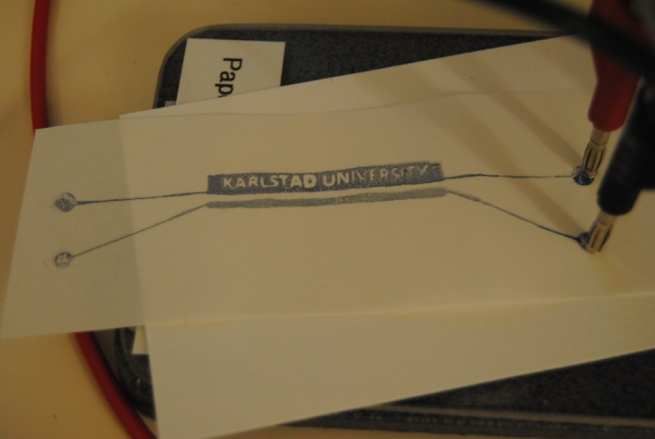
List of Symbols and Abbreviations

Abbreviations

      AU          -    absorbance unit
      BSE         -    Backscattered electron
      CD          -    cross machine direction
      CNT         -    carbon nanotubes
      DMSO        -    Dimethyl sulfoxide
      EDS         -    Energy Dispersive X-ray Spectroscopy
      ESCA        -    Electron Spectroscopy for Chemical Analysis
      FFT         -    fast Fourier transform
      HOMO        -    highest occupied molecular orbital
      IS          -    impedance spectroscopy
      LUMO        -    lowest unoccupied molecular orbital
      IL          -    ionic liquid
      MCC         -    microcrystalline cellulose
      MD          -    machine direction
      MWCNT       -    multi-wall carbon nanotubes
      NMP         -    N-methyl-2-pyrrolidone
      PEDOT:PSS   -    poly(3,4-ethylenedioxythiophene)/poly(4-styrene sulfonate)
      PSI         -    phase shift interferometer
      RBA         -    relative bonded area
      RTIL        -    room temperature ionic liquid
      SWCNT       -    single wall carbon nanotubes
      VSI         -    vertical scanning interferometer
      XPS         -    X-ray Photoelectron spectroscopy

Symbols

      a           -    cross-section area (m2)
      A           -    measured absorbance (AU)
      E           -    applied electric field (N/C)
      E1          -    heat of adsorption of layer 1 (J)
      EL          -    heat of adsorption of higher layers (J)
      Ea          -    activation energy (eV or J)
      Eb          -    binding energy (eV or J)
      Ek          -    kinetic energy (eV or J)
      e           -    elementary charge (1.602176487 x 10 -19 C)
      ei          -    electronic charge of ion of species i (C)
      ε           -    molar absorptivity (m2/mol)
      εrs         -    relative permittivity of the dispersion medium
      ε0          -    permittivity of vacuum (F/m or C² N-1 m-2)
                                        v
η - dynamic viscosity (Pa s)
Fa - resistance force (N)
Fr - resistance force (N)
γ - surface tension (N/m)
h - Planck’s constant (6.626068(33) × 10-34 J s)
I - intensity of transmitted light
I0 - intensity of the incident light at a given wavelength
J - current density (A/m2)
kB - Boltzmann’s constant 8.617 343(15)×10−5 (eV/K)
lf - fiber length (m)
µi - mobility of the charge carrier species i [cm2/(V s)]
ni - density charge of material i (cm-3)
Ni - concentration of generating sites of ion species i (cm-3)
υ - light frequency (1/s)
φ - work function of spectrometer (eV or J)
l - distance between electrodes (m)
r - pore radius (m)
R - resistance (Ω)
σdc - direct current bulk conductivity (S/cm)
σv - conductivity of material (S/cm)
t - thickness of the paper (m)
T - tensile strength (kN/m)
τb - breaking stress (Pa)
θ - contact angle (º)
Ui - energy required to dissociate the ion i (eV)
v - amount of gas adsorbed (g or cm3)
V - Voltage (V)
vm - amount of monolayer adsorbed (g or cm3)
w - solid content of the active substance (g)
wf - fiber width (m)
y - number of electron-hole pairs
Z - zero span strength of paper
ζ - zeta potential (mV)
viTable of Contents
Abstract .................................................................................................................................................. i
List of Papers ...................................................................................................................................... iii
List of Symbols and Abbreviations ................................................................................................... v
Table of Contents .............................................................................................................................. vii
1 Introduction ...................................................................................................................................... 1
2 Conducting Materials ....................................................................................................................... 3
2.1 Conducting Polymers ............................................................................................................... 3
2.1.1 Background......................................................................................................................... 3
2.1.2 Doping of Conducting Polymers .................................................................................... 5
2.1.3 Applications of Conducting Polymers ............................................................................ 6
2.2 Multi-wall Carbon Nanotubes ................................................................................................. 7
2.2.1 Background......................................................................................................................... 7
2.2.2 Physical Properties............................................................................................................. 7
2.2.3 Applications of Carbon Nanotubes ................................................................................ 8
2.3 Ionic Liquids .............................................................................................................................. 9
2.3.1 Background......................................................................................................................... 9
2.3.2 Room Temperature Ionic Liquids ................................................................................... 9
2.2.3 Applications of RTILs ....................................................................................................10
3 Paper as a Renewable Material .....................................................................................................11
3.1 The Cellulosic Fiber Network ............................................................................................... 11
3.1.1 Wood Fibers .....................................................................................................................11
3.1.2 Paper and Papermaking ..................................................................................................12
3.2 Surface Treatment of Paper................................................................................................... 13
3.3 Some Paper Properties ........................................................................................................... 15
3.3.1 Porosity and Surface Area ..............................................................................................15
3.3.2 Surface Roughness...........................................................................................................15
3.3.3 Tensile Strength ...............................................................................................................16
3.3.4 Wetting and Liquid Penetration.....................................................................................17
3.3.5 Electrical Properties ........................................................................................................18
3.4 Some Characterization Techniques ...................................................................................... 19
3.4.1 Spectrophotometry ..........................................................................................................19
3.4.2 Scanning Electron Microscopy - Energy Dispersive Spectroscopy..........................20
3.4.3 X-ray Photoelectron Spectroscopy ...............................................................................22
3.4.4 Raman Spectroscopy .......................................................................................................23
3.4.5 Mercury Porosimetry.......................................................................................................24
3.4.6 BET Area ..........................................................................................................................25
3.4.7 Contact Angle Measurement ..........................................................................................26
3.4.8 Impedance Spectroscopy ................................................................................................27
3.4.9 Four-Probe Technique....................................................................................................28
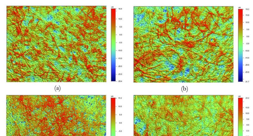
3.4.10 Optical Profilometry .....................................................................................................29
4 Preparation of Conductive Paper.................................................................................................31
vii4.1 Materials ................................................................................................................................... 31
4.1.1 Substrates ..........................................................................................................................31
4.1.2 Conducting Materials ......................................................................................................31
4.1.3. Additives ..........................................................................................................................32
4.2 Adsorption of PEDOT:PSS onto MCC .............................................................................. 32
4.3 Fiber Beating and Papermaking ............................................................................................ 32
4.4 Dip Coating of Base Paper into PEDOT:PSS Dispersion ............................................... 33
4.5 Deposition of PEDOT:PSS Blends into the Fiber Network ........................................... 33
4.6 Deposition of Ionic Liquid into the Fiber Network .......................................................... 34
4.7 Surface Sizing .......................................................................................................................... 34
4.8 Screen Printing and Coating of Electrochromic Polymer ................................................. 34
5 Interaction Between PEDOT:PSS and Cellulosic Material......................................................35
5.1 Adsorption Isotherm .............................................................................................................. 35
5.2 The Effect of pH and Salt Concentration ........................................................................... 36
6 Electroconductive Paper ...............................................................................................................39
6.1. The Conducting Polymer in the Fiber Network ............................................................... 39
6.1.1 Scanning Electron Micrographs ....................................................................................39
6.1.2 PEDOT to PSS ratio.......................................................................................................40
6.2 Some Factors Affecting the Bulk Conductivity .................................................................. 42
6.2.1 The Influence of Fiber Beating and Sheet Forming ...................................................43
6.2.2 The Influence of Calendering ........................................................................................45
6.2.3 The Influence of Organic Solvents ...............................................................................45
6.2.4 The Influence of TiO2 Pigments ...................................................................................48
6.2.5 The Influence of Multi-Wall Carbon Nanotubes ........................................................50
6.3 Some Changes in Surface Properties .................................................................................... 52
6.3.1 Contact Angle ..................................................................................................................52
6.3.2 Porosity and Surface Area ..............................................................................................55
6.4 Tensile Strength....................................................................................................................... 56
7 Ion-Conductive Paper ...................................................................................................................59
7.1 Ionic Paper ............................................................................................................................... 59
7.1.1 The Effect of Relative Humidity ...................................................................................59
7.1.2 The Effect of Temperature ............................................................................................60
7.2 Surface Sizing .......................................................................................................................... 61
7.3 Demonstration of Electrochemical Performance .............................................................. 64
8 Conclusion ......................................................................................................................................67
9 Future Aspects and Challenges ....................................................................................................69
Acknowledgements ...........................................................................................................................70
References ..........................................................................................................................................71
viii1 Introduction
The search for renewable materials, and the utilization of these materials in various
industries, is currently the major concern of this planet. This is because those fossil-based
materials which are being utilized are running out, and their production creates ecological
imbalance since they cannot be easily replenished. Awareness of this fact promotes research,
both in academia and in industry, to either completely remove fossil-based materials or to
add renewable materials to its components.
The 21st century marks the rapid advancements of information technology. One of the
essential features of this development is electronics. Humanity has been utilizing various
advanced electronic-based products and applications such as mobile phones, computers and
the internet, TV, etc in the last decades. A new field of electronics is emerging too; flexible
electronics. The accidental discovery of conducting polymers in the late 1970s by Heeger,
Shirakawa, and McDiarmid gave birth to the field of organic electronics (Chiang et al 1977).
Now, it is possible to construct electronic components on any surface, on both rigid and
flexible substrates. The conducting polymer can be deposited through printing (Ballarin et al
2004; Nelson 2007), coating (Denneulin, 2008; Jönsson et al 2002; Kemerink et al 2004),
casting (Heeger et al 1997) or layer-by-layer deposition (Agarwal et al 2006; Lvov et al 2006;
Qian et al 2006; Wistrand et al 2007; Gerhardt et al 2008) on any types of substrate. The
conducting polymer can be deposited in macro-, micro-, and nano-scales. Plastics, by far, are
the most widely utilized flexible substrate.
Another alternative flexible material is paper. Its renewability and low cost of production are
two of its most attractive properties. Since its first discovery in the Nile river valley of Egypt
in 600 BC where it was originally called papyrus, the use of paper has been evolving through
the years (Roberts 1996). Paper has been used for the storage of information, in cooking, as
a hygienic product, in packaging, in the arts and decorations, etc. It has also been used as
insulating material in electrical cables owing to its intrinsically high resistivity. Lately,
research on converting paper into a conductive material is increasing (Agarwal et al 2006;
Lvov et al 2006; Qian et al 2006; Wistrand et al 2007). Although paper was modified into a
conductive material already in the 1960s, the types of material being deposited and their uses
are now different. As a porous material, paper has a great potential in large-area electronics.
There is a need for flexible and renewable substrates in electronics. Since the field of flexible
electronics is young, the utilization of paper as flexible substrate at its early stage would
reduce the usage of fossil-based materials such as plastics.
1The aim of this study is to prepare and characterize conductive paper as substrate or
component wherein an electronic device can be constructed by the deposition of conducting
materials. It also attempts to demonstrate that conductive paper can be a compact and
robust electronic device in itself. This thesis consists of five papers. Paper I deals with the
understanding of the interaction between cellulosic materials and the conducting polymer
poly(3,4-ethylenedioxythiophene) doped with poly(4-styrene sulfonate) (PEDOT:PSS) using
microcrystalline cellulose (MCC) as a model surface. A commercial paper is also dip-coated
into the PEDOT:PSS dispersion and the coated paper is characterized. In paper II, a
commercial base paper is coated with blends of PEDOT:PSS and various organic solvents.
The effect of organic solvents on the conductivity of the coated paper is investigated. Paper
III shows the effect of fiber beating on the conductivity of PEDOT:PSS-coated paper while
Paper IV deals with the effect of adding multi-wall carbon nanotubes (MWCNT) to the
PEDOT:PSS dispersion. In Paper V, an ionic liquid is deposited into the fiber network and
the PEDOT:PSS is coated and screen printed to demonstrate that the conductive paper can
facilitate ionic flow and hence facilitate electrochemical reactions.
22 Conducting Materials
Conducting materials are substances that allow the flow of ions and/or electrons along the
structure. Generally, materials can be classified into insulators, semiconductors and
conductors based on their conductivities, as shown in Figure 2.1. Conductivity is a measure
of a material’s ability to conduct an electric current (electrical conductivity) or ionic charge
carriers (ionic conductivity). It was in the 1970s when these two new classes of
macromolecules started to develop (Armand et al 1997). The electronic conductive materials
are doped compounds, in which a compound is inserted to induce conductivity, in a redox
process, though the associated motion of ionic and electronic charges. Ionic conductivity, on
the other hand, is obtained by dissolving a salt in a suitable polymer lattice.
Figure 2.1 Range of electrical conductivity from insulators to metals (Ajayaghosh 2004).
There are a number of materials that facilitate the flow of either ions or electrons. In this
study, three conducting materials are considered: conducting polymer, multi-wall carbon
nanotubes (MWCNT) and ionic liquid.
2.1 Conducting Polymers
2.1.1 Background
The accidental discovery of a conducting polymer in the 1970s by doping polyacetylene
(Figure 2.2) with iodine opened up many possibilities in the field of electronics (Chiang et al
1977, Shirakawa et al 1974). A conducting polymer is a conjugated polymer with alternating
single and double bonds along the backbone resulting in π-conjugated network. The π-
conjugated polymer consists of a regular alternating system of single (C-C) and double
(C=C) bonds which leads to a lower band gap energy, Eg in the delocalized π-system
(Salaneck et al 1996).
3H H H H H H
C C C C C C
C C C C C C C C
n n
H H H H H H H H
2
Figure 2.2 The structure of trans-polyacetylene and schematic diagram of sp pz hybridized carbon.
Conjugated polymers are sp2pz hybridized polymers, where the sp2pz hybridized linear
carbon chain is responsible for the conductivity (Heeger et al 2010). The three in-plane
sigma-orbitals of the sp2 hybridized carbons create the “backbone”; two of them being
bonded to the neighboring carbons and the third sigma-orbital being bonded to a hydrogen
atom. The fourth electron resides in the pz orbital. This one-electron picture of the pz
electron being decoupled from the backbone sigma-orbitals gives these polymers special
electrical properties. Traditional polymers such as polyethylenes are electrical insulators
because all of the valence electrons are bound in sp3 hybridized covalent bonds which means
that there are no mobile electrons to participate in electronic transport.
Electronically, conducting polymers are extensively conjugated molecules that possess a
spatially delocalized band-like electronic structure (Skotheim 1986). These bands stem from
the splitting of interacting molecular orbitals of the constituent monomer units in a manner
reminiscent of the band structure of solid-state semiconductors, as shown in Figure 2.3. The
band gap is defined by the energy difference between the Lowest Unoccupied Molecular
Orbital (LUMO) and the Highest Occupied Molecular Orbital (HOMO).
Conduction Band
LUMO
Energy
Band gap
HOMO
Valence Band
Figure 2.3 Band structure in an electronically conducting polymer.
The main difference between conjugated and non-conjugated polymers is the presence of
the extended π-electron systems in the former (Springborg et al 2001). The conductivity, σ,
4of a conjugated polymer is proportional to the number of charge carriers, n and their
mobility, µ. Since the band gap of a conjugated polymers is normally large, n is very small
under ambient conditions. Consequently, conjugated polymer are insulators or
semiconductors with too large energy gaps in their neutral state and no intrinsically
conducting organic polymer is known at this time (Heeger et al 2010). Typical values of
conductivity of polythiophene and polyacetylene are between 10-10 and 10-8 S/cm. A
polymer can be made conductive by a process called doping.
2.1.2 Doping of Conducting Polymers
The doping of a conducting polymer can be performed via oxidation (p-doping) and/or, less
frequently, by reduction (n-doping) of the polymer to generate mobile charge carriers. To
compensate for the charge difference, due to the removal or addition of electrons in the
semiconducting polymer, a counter-ion is inserted into the structure. Doping is reversible
and does not interrupt the polymer chain interaction because of the strong covalent bonds
within the chains of the polymer.
A number of doping methods are currently employed, including chemical, electrochemical,
photo-induced, and interfacial doping (Heeger et al 2010). In electrochemical doping, the
polymer is oxidized or reduced by the electrodes when a voltage is applied. The counter-ion
moves from the electrolyte into the polymer, and it diffuses into the structure between the
chains. Doping by acid-base chemistry as in the case of polyaniline occurs through a
protonation-induced changed in the π-electron structure with no addition of electrons to or
widrawal of electrons from the π-electron system. This type of protonation leads to an
internal redox reaction resulting in the conversion from semiconductor to metal. In
photoinduced doping, the photoexcitation of the polymer excites electron from the filled π-
band to the empty π*-band. This means local oxidation of the conjugated polymer backbone
and leads to mobile charges, photoinduced positive and negative polarons, and thereby to
photoinduced conductivity.
(π-polymer)n + hν → [(π-polymer)+y + (π-polymer)-y]n
where y is the number of electron-hole pairs. The interfacial doping relies on the charge
injection at the metal-semiconducting polymer interface as in the case of polymer light-
emitting diodes. Classic conductive polymers are typically derivatives of polyacetylene,
polyaniline, polypyrrole, and polythiophene. One of the most widely used conducting
polymers is poly(3,4-ethylenedioxythiophene) doped with polystyrene sulfonate or
PEDOT:PSS (Figure 2.4).
5Figure 2.4 The structure of PEDOT:PSS.
It consists of conducting PEDOT molecules surrounded by non-conducting PSS molecules.
The films of PEDOT have been found to have a very high conductivity (>200 S/cm)
(Aleshin et al 1997) and they are stable (Pei et al 1994). The presence of PSS in the
PEDOT:PSS enables the complex to form a highly stable dispersion in water, and it has a
high visible light transmissivity and robust film formation properties with substantial
conductivity (~1-10 S/cm) (Wang et al 2005). This polymer exhibits many attractive
properties in terms of ease of processing, high conductivity, and environmental stability
(Groenendaal et al 2000; Xing et al 1997).
2.1.3 Applications of Conducting Polymers
The discovery of conducting polymers is quite revolutionary in the electronics industry and
is beginning to have a large impact on other industries. Conducting polymers can be used in
polymer light-emitting diodes, light-emitting electrochemical cells, as laser materials, in
photovoltaic cells and photodetectors, and in polymer field effect transistors (Heeger et al
2010). The use of poly(fluorene) homopolymer and copolymer in detecting DNA, RNA,
some proteins, glucose and other small molecules adds to the usefulness of conjugated
polymer as biological and chemical sensors (Bazan and Wang 2008). Toxic gases can also be
detected by using organic transistor-based phosphonate gas sensor (See et al 2008).
PEDOT:PSS-based electrochemical transistors is useful in ion-to-electron transduction and
in sensor signal amplification (Berggren et al 2008).
62.2 Multi-wall Carbon Nanotubes
2.2.1 Background
Carbon nanotubes (CNT) are allotropes of carbon having cylindrical nanostructures with
remarkable electronic and mechanical properties. In 1991, Iijima first reported the
observation of multi-wall carbon nanotubes (MWCNT) and, after less than two years, the
single-wall carbon nanotubes (SWCNT) were discovered by him and his coworkers (Iijima
1991, Dresselhaus et al 2001). Since then, carbon nanotubes have been the subject of
widespread theoretical and experimental investigations. Carbon nanotubes can be produced
by laser vaporization (Guo et al 1995), carbon arch method (Iijima 1991, Ebbesen et al
1992), and chemical vapor deposition (José-Yacamán et al 1993). Naturally, nanotubes can
also be present in the flames produced from burning methane (Yuan 1991) or ethylene
(Yuan 1991), benzene (Duan et al 1994), and in the soot from both indoor and outdoor air
(Murr et al 2004). However, irregular sizes and quality were observed in these naturally
occurring nanotubes due to highly uncontrolled conditions. Figure 2.5 shows the structure
of multi-wall carbon nanotubes. The MWCNTs are typically 2-25 nm in outer diameter, 1-5
nm inner diameter and a few micrometers in length.
Figure 2.5 Structure of multi-wall carbon nanotubes (MWCNT).
2.2.2 Physical Properties
Carbon nanotubes are nanomaterials with a very high aspect ratio that varies from 500 to
100 000 (Wang et al 2003). Carbon nanotubes are especially interesting because of their
exotic electronic properties (Dresselhaus et al 2001). A MWCNT is composed of a set of
coaxially arranged SWCNTs of different radii (Iijima 1991). SWCNTs can be cliassified as
either semiconductors or metals. In an ideal case, 1/3 of SWCNTs would be metallic and
2/3 semiconducting. Assuming that neighboring sheets do not interact, the electronic
properties of MWCNTs would be similar to a set of independent SWCNTs with radii in the
7range of a few nanometers to ≈ 10 nm. In the case of MWCNTs with larger diameters (~20
nm), the bandgaps are only Eg ≈ 44meV (Forró et al 2001). Carbon nanotubes have a
magnetic property, as can be observed by Electron Spin Resonance (ESR) showing a
mesoscopic nature in their spin relaxation. MWCNTs exhibit field and light emission when
individual MWCNTs are attached to a conducting wire and the current is measured after
applying a negative potential to the wire (Rinzler et al 1995, Bonard et al 1998).
In terms of tensile strength and elastic modulus, carbon nanotubes are the strongest and
stiffest materials yet discovered owing to the covalent sp2 bonds formed between the
individual carbon atoms. The reported tensile strength of a MWCNT is about 63 GPa (Yu et
al 2000) and Young’s modulus is up to 1000 GPa (Iijima et al 1991, Wei et al 2003). Carbon
nanotubes exhibit good thermal conduction characteristics. It is also well known that
MWCNTs tend to form aggregates in solution which can be reduced by physical or chemical
alteration (Khosla et al 2010).
2.2.3 Applications of Carbon Nanotubes
There is a wide range of applications for these cylindrical carbon molecules because of their
novel properties, as mentioned. These include nanotechnology, electronics, optics, and the
architectural field. Attempts are also being made to use carbon nanotubes for ballistic
resistance as a potential component in body armor (Zhang et al 2007). Since CNT have the
right combination of properties – nanometer diameter, structural integrity, high electrical
conductivity, and chemical stability, they are good electron emitters (Forró et al 2001).
Prototype cathode-ray lighting elements, flat display panels and gas-discharge tubes (in
telecom networks) are being made (Ajayan et al 2001). They are being considered for energy
production and storage and in filled composites (Cui et al 2009, Ajyan et al 2001). The bulk
nanotubes may never achieve the mechanical property similar to the individual tubes but the
composites nevertheless have strengths sufficient for many applications. It can be added to
epoxy for improved mechanical properties (Bonnamy et al 2004, Ajayan et al 1998). Other
applications of CNT may include tips for atomic force microscopy and tissue engineering
(Zanello et al 2010).
82.3 Ionic Liquids
2.3.1 Background
Ionic liquids (ILs) are generally salts in the liquid state based on a substituted heterocyclic
cation and an organic or inorganic anion. One of the first ionic liquids synthesized was
ethylammonium nitrate in 1914, although at that time it was called a fused salt (Walden
1914). The term “ionic liquid” was first used in 1943 (Barrer 1943). The melting point of ILs
is below 100 ºC. The species of cation and anion and the length of the alkyl groups on the
cation greatly influence their physical and thermal properties (Marsh et al 2002). Ionic liquids
are made up of ions and short-lived ion pairs. Any salt that melts without decomposing or
vaporizing usually yields an ionic liquid. Other terms for these substances include liquid
electrolytes, ionic melts, ionic fluids, fused salts, and ionic glasses. Since the ionic bonds are
stronger than the van der Waals forces between the molecules of an ordinary liquid,
common salts tend to melt at a higher temperature than other solid molecules. There are ILs
that are liquid at or below room temperature, and these are called room temperature ionic
liquids (RTIL).
2.3.2 Room Temperature Ionic Liquids
RTILs have gained popularity in recent years. Figure 2.6 shows the structures of the
commonly used cations in ILs, viz.: alkyimidizalium [R1R2IM]+, alkylpyridium [RPy]+,
tetraalkylammomium [NR4]+ and tetraalkylphosphonium [PR4]+. The commonly used anions
are hexafluorophosphate, tetrafluoroborate, nitrate, methane sulfonate (mesylate),
trifluoromethane sulfonate, and bis-(trifluoromethanesulfonyl) amide (Marsh et al 2009).
R1 R2 + +
N+ N +N NR4 PR4
R1 R2
Imidazolium Pyridinium Ammonium Phosphonium
Figure 2.6 Commonly used cations for ionic liquids.
One interesting RTIL is 1-butyl-3-methylimidazolium tetrafluoroborate ([bmim]BF4) with a
melting point of about −80 °C, which is a colorless liquid with high viscosity at room
temperature (Lee et al 2004). Although much research effort has been concentrated on
dissolving cellulose in recent years (Marsh et al 2009), [bmim]BF4 is an IL that does not
dissolve cellulosic materials (Rogers et al 2002) and it is suitable as wood preservative
(Pernak et al 2004). Figure 2.7 shows the chemical structure of [bmim]BF4. Some of the
attractive properties of RTILs that are useful in a sustainable process are biodegradability
9(Gathergood et al 2003), low volatility (Earle et al 2006, Zhu et al 2006) and low toxicity
(Jastorff et al 2003, Wasserscheid et al 2002).
N + N BF4 -
Figure 2.7 Chemical Structure of [bmim]BF4.
2.2.3 Applications of RTILs
RTILs have been used in biocatalysis and electrochemistry. They serve as electrolytes in solar
cells, as double-layer capacitors and in the electrodeposition of metals (Matsunaga 2002, El
Abedin et al 2006). They are considered as “green” solvents due to their low volatility (Zhu
et al 2006). The applications of RTILs are increasing in various areas including chemical
reaction (Ganske et al 2005, Mori et al 2005), electrochemical (Zhao et al 2004, Lu et al
2006), separation applications (Yao et al 2009, Ragonese et al 2009), inorganic nanomaterials
(Cao et al 2005, Liu et al 2007), the food industry (Fort el al 2006) and cellulose processing
(Marsh et al 2009).
103 Paper as a Renewable Material
One of the greatest discoveries of mankind is paper. For the last two thousand years, it has
impacted humanity in a subtle way. One can always find paper at home, in the office, at the
grocery stores, etc. It is one of the few inventions that have little impact on the environment
because it is composed of cellulosic materials. Cellulose is the most abundant organic
compound on the planet and the fact that cellulosic plant materials are continually being
generated means that paper is a renewable material.
Since paper is an everyday material, the average person might think it to be a simple material
but in reality it is a morphologically, physically, and chemically complex material. Its
production process is also highly sophisticated in the sense that it involves a high-speed
filtration process which yields a weak wet fibrous network. The fiber web then is pulled
continuously, despite its weakness, through the pressing and drying sections of the paper
machine to the reel at high speeds so that the web undergoes some extension (Roberts
1996).
3.1 The Cellulosic Fiber Network
3.1.1 Wood Fibers
The tubular wood fibers are composed of cellulosic elements produced from trees. They are
primarily extracted from hardwood (deciduous) and softwood (coniferous) trees. Softwood
fibers have prominent pits of characteristic shapes along their radial surfaces and they have
relatively long average length, i.e. 3-4 mm (Clark 1985). The hardwood fibers are shorter (1-
1.5 mm length) and more slender than the softwood fibers. In general, wood fibers contain
about 20-30% lignin, 25-35% hemicellulose, and 45-50% raw cellulose (pure cellulose,
mannan, pentosan) (Clark 1985). The amount of these components varies depending on the
type of wood fiber. Bundles of cellulose molecules of about 35 Å are called elementary fibrils
or crystallites. Nanofibrils are bundles of elementary fibrils with diameter 35-300 Å whereas
microfibrils have diameter 300 nm - 0.3 µm. Larger bundles (>0.3 µm) are called fibrils,
which collectively include all elements that make up a fiber. It is also possible that fibrils and
smaller elements are in the form of thin sheets. All the elements of a fiber are held together
with hydrogen bonds.
Fiber properties are greatly influenced by the method of liberating the fibers from the wood
matrix known as pulping. There are two general pulping methods, namely mechanical and
chemical pulping. In mechanical pulping, wood chips are ground or fed into the center of
two refining discs, the fibers are released and the mechanical pulp is obtained. Mechanical
11pulp fibers are stiff and mostly uncollapsed, and the pulp yield is about 90 to 100%
depending on the mechanical method used (Brännvall 2009, Clark 1985). Mechanical pulp
has also a large portion of fines, which consist of fragments from the fiber wall and broken
fibers. In chemical pulping, the fibers are liberated from the wood matrix by using caustic
soda that removes most of the lignin. The most widely used chemical pulping method is
kraft cooking (Brännvall 2009). The cooking chemicals used are sodium hydroxide, and
sodium sulfide. Chemical pulp fibers are more flexible than mechanical pulp fibers.
The pulp undergoes bleaching so that the resulting paper has better print quality, cleanliness,
and ability to resist ageing. Bleaching is usually performed in several stages, with the use of
different chemicals at each stage. Bleaching chemicals that are being used are hydrogen
peroxide, chlorine dioxide, ozone, and peracetic acid. Pulp beating/refining is another step
performed to achieve pulp properties suitable for papermaking. Beating is a general term
which means either batch treatment of a pulp slurry in a beater or continuous treatment of
thick slurry through a refiner (Clark 1985). The major effects of beating include shortening
or cutting of fibers, external fibrillation, abrasion, surface splitting, internal splitting, bruising,
and crushing. Other effects of beating are production of debris, longitudinal compression,
kinking/curling of fibers, redistribution of hemicelluloses from the interior of the fiber to
the exterior, increase in the drainage resistance, and increase in tensile strength.
3.1.2 Paper and Papermaking
Paper is made up of a cellulosic fiber network as shown in Figure 3.1. It was around 105 AD
in China that the art of papermaking was first invented by reducing fibrous matter to a pulp
in water and forming it as a network of fibers (Pauluparo and Gullichsen 2000). The first
continuous paper machine was invented in 1779 and the fourdrinier paper machine was
invented in 1801 (Clark 1985). Nowadays, with the growing demand for paper, fibers from
wood are increasingly being used (Niskanen et al 1998).
Paper can be handmade or machine-made from dilute pulp slurry with ~ 0.6% dry solids
content (Bränvall 2009). The handmade paper is either a part of industrial history or often
practiced papermaking procedure in laboratories. The commercial paper production is run at
large paper mills using wide and automated paper machines for production efficiency and
reliability. Handmade paper normally has randomly orientated fibers (isotropic) while
machine-made papers displays varying degree of anisotropy due to the velocity difference
between the nozzle of the headbox and the wire. At the points of contact between fibers,
strong bonds are formed once the fibers have been dried, due to hydrogen bonds between
the polysaccharides in the fiber networks. In general, the fibers lie predominantly in the
12plane of the sheet and are broadly parallel to each other in the z-direction. The fiber
orientation directly affects the in-plane mechanical properties and dimensional stability of
paper (Niskanen et al 1998). The areal mass distribution is dependent on the distribution of
the fibers in the x-y plane. This local grammage distribution has great influence on many
sheet properties. Some properties, e.g. mechanical strength, also depend on the bonding
between fibers and not merely on the nature of the fiber distribution. The bonding of fibers
and the fiber strength are influenced by pulping and bleaching, and by the fiber preparation
conditions employed prior to sheet formation.
Figure 3.1 Scanning electron micrograph of a paper surface.
3.2 Surface Treatment of Paper
The chemical and physical properties of paper can be tailored to suit its specific applications
since paper is a versatile material. One way to modify the properties of paper is by modifying
the fibers or by adding fillers before the headbox. Various additives such as sizing agents,
optical brightening agents, polyelectrolyte, fillers, etc are added to the stock to improve the
formation, enhance the paper properties, or add functionalities to the paper. Later in the
papermaking process the surface of the paper maybe modified by surface sizing, coating, or
calendering.
Paper coating is performed to alter the surface properties of the final paper product such as
graphical and barrier properties. Coating methods include dip coating, rod coating, knife
coating, blade coating, forward and reverse roll coating, slot and extrusion coating, slide
coating and curtain coating (Cohen 1992). Normally, the coating formulations contain high
13solids content, i.e. ~25-70% for barrier polymer dispersion coating (Kimpimäki and
Savolainen 1997) and ~50-70% for pigment coating (Attrup and Hansen 1997). In
laboratory rod coating, the coating material is placed in front of the wire-wound rod (Figure
3.2). As the rod moves, the coating material forms a wet film on the surface of the paper that
corresponds to the thickness of the wire diameter. The laboratory rod coating is often used
as a first step in a development process, both in industry and in academia. This is because
the results correlate, within certain boundaries, to pilot and production scale and it is
inexpensive.
Figure 3.2 Surface treatment of paper using rod coating.
The coating material may also penetrate deep into the fiber network, thereby modifying both
the surface and bulk properties of paper as shown in Figure 3.3, although this is not often
practiced. This is accomplished by using rod of thin wire diameter, slow movement of the
rod, low solid content coating mixture, and using a highly porous base paper (e.g. made from
unbeaten or slightly beaten fibers). In roll coating, the penetration of coating suspension is
achieved by increasing the nip pressure. The viscosity of the coating mixture is also an
important parameter that influences its penetration into the paper. The coated paper is then
dried in an oven at a specified temperature and time.
wire-wound
rod
coating material
base paper
Figure 3.3 Schematic picture of rod coating showing the penetration of conducting material into the base
paper.
14Another surface treatment process is calendering, wherein the paper is compressed between
two rolls. The rolls can be lined with different surface material; normally metal or polymer,
to alter the nip length. Heating these rolls softens the paper material and increasing the line
load increases the compression which can be used to govern the induced deformation.
Calendering reduces the roughness, increases the gloss and improves the printability of paper
and paperboard (Perry 1993, Holik 2006).
3.3 Some Paper Properties
3.3.1 Porosity and Surface Area
Paper is a porous material as shown in Figure 3.1. Porosity is the ratio of the pore volume to
the total volume. The pores in papers are categorized into micro- and macro-pores. The
micropore structures have diameters of ≤ 1.5 µm and consist of fiber pores, fine inter-fiber
voids, and fine voids between fibers and fine materials. Macropores have diameters greater
than 1.5 µm and consist of larger inter-fiber voids, and uncollapsed pulp fiber lumens
(Yamauchi et al. 1979, Yamauchi and Kibblewhite 1988). The quantity of macropores is
reduced by fiber beating because the fibers become more consolidated, with greater inter-
fiber bonding. The specific internal surface area of paper is the internal surface area of pores
per unit mass of sample. Porosity is one of the important factors to consider in designing a
paper that may allow or hinder material penetration into the structure.
3.3.2 Surface Roughness
Since paper is a network of cellulosic fibers, the uneven surface of paper creates roughness.
Roughness refers to the uneven surface of paper or board. It is difficult to distinguish
between the end of the surface and the beginning of the internal pore structure of paper.
Kajanto et al (1998) categorized roughness into three components according to the in-plane
resolution: optical roughness (< 1 µm), micro-roughness (1 – 100 µm), and macro-roughness
(0.1 – 1 mm). Roughness is significant in printing papers, graphical and packaging boards. It
greatly influences the optical properties of paper such as gloss, ink absorption, and the
amount of coating necessary in order to achieve good coverage (Kajanto et al 1998). To
decrease the surface roughness and achieve good barrier properties against water, air, grease,
etc., paper can be surface sized. Figure 3.4 shows the surface of a paper covered by surface
sizing agent and this maybe compared to the base paper in Figure 3.1. Another way of
decreasing the surface roughness is by calendering as described in Section 3.2. The paper
web is pressed in one or more “rolling” nips formed by rollers (Feldmann 2006).
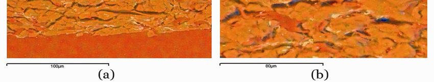
15Figure 3.4 Scanning electron micrograph of the cross section of paper showing a portion of the surface
covered by a surface sizing agent.
3.3.3 Tensile Strength
Tensile strength measures the load a paper specimen can withstand before breaking. It is the
breaking force per unit area (in MPa), which has the same unit as the elastic modulus. Often,
tensile strength is expressed in kN/m, i.e the breaking force divided by the width of the strip
(Niskanen et al 1998). The tensile index is tensile strength divided by the basis weight
(Nm/g). The strength of paper is influenced by the gradual failure of inter-fiber bond and
fiber rapture. Figure 3.5 shows the typical load (stress) versus elongation (strain) curve of
paper. Stress is being transferred to and from every fiber through many bonds. Paper
stretching gradually opens the inter-fiber bonds. Bond failure occurs when the shear force
on the bond exceeds its shear strength.
tensile strength
Load
strain at break
Elongation
Figure 3.5 Schematic sketch of typical load-elongation curve of paper.
16The tensile strength depends on the “weak” points of the specimen. A number of models
have been presented to show how the fiber and bond failures affect the paper strength. One
of the most celebrated empirical models is the Page equation (Page 1969),
(3.1)
್
where T is the tensile strength, Z is the zero span strength of paper, RBA is the relative
bonded area, wf is the fiber width, lf is the fiber length, and τb is the breaking stress of bonds
(breaking force over area). The Page model started from the experimental observation that
the tensile strength is proportional to the fraction of broken fibers along the rupture line in
beating trials (Niskanen et al 1998). This equation suggests that the inverse of tensile
strength is linearly proportional to the inverse of fiber length, fiber strength and RBA. Fiber
beating improves the tensile strength due to more flexible fibers, which facilitate the
formation of fiber-fiber bond. It is found that machine-made papers have different cross
machine direction (CD) and machine direction (MD) tensile strength. The tensile strength of
paper is measured using a mechanical tester. A strip of paper is clamped at both ends and
slowly pulled apart until it breaks. ISO 1924 describes the procedure for the test.
3.3.4 Wetting and Liquid Penetration
Wood fibers are hydrophilic in nature which means that their network is also hydrophilic. In
principle, a liquid wets the surface only if its surface tension is lower than that of the surface
(Dullien 1992). Wetting is a surface phenomenon which is influenced by chemical
composition of the surface layers down to monomolecular thickness. Another factor that
affects wetting is the surface morphology. It is reported that drops of non-wetting liquids
tend to exhibit higher contact angles on rough surfaces and extend more readily along
grooves or fibers than across them (Oliver and Mason 1976). On the other hand, wetting
liquids exhibit a lower contact angle on a rougher surface of the same material. The reason is
that all systems tend to move to the direction of reducing surface free energy. The liquid
penetration into the fiber network can be interrupted by dislocation in local surfaces such as
sharp edges of mineral fillers, e.g. clay and calcium carbonate or ridges, on fibers. Local non-
uniformity and anisotropy in wetting behavior are due to variation and orientation in fiber
and network morphology (Lyne 2002). Wetting can be altered by deposition of chemical
agents either on pulp fibers or by surface sizing the paper (Nyström et al 2006). Beating the
fiber to a considerable degree is another factor that influences wetting behavior of paper by
creating a “smoother” paper surface (Clark 1985) due to a decrease in macroporosity.
17You can also read