2020TG for Gauge Pressure - Multi Visionä Digital Transmitter
←
→
Page content transcription
If your browser does not render page correctly, please read the page content below
Multi Visionä         2020TG for Gauge Pressure
Digital Transmitter          and Level
                      2020TA for Absolute Pressure

Instructions          42/15-753-7 EN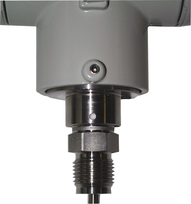
Contents                                                                                                   structions is neither part of nor provided for changing a previous or
                                                                                                           existing agreement, promise or legal relationship. All obligations of
                                                                                               page
                                                                                                           ABB Automation Products GmbH result from the respective sales
1    Safety. . . . . . . . . . . . . . . . . . . . . . . . . . . . . . . . . . . . . . . . . . . . . . 2
     General safety precautions and health protection . . . . . . . . . 2                                  contract which also comprises the complete and solely valid war-
     Correct usage . . . . . . . . . . . . . . . . . . . . . . . . . . . . . . . . . . . . . 2             ranty clauses. Such contractual warranty clauses will neither be
                                                                                                           limited nor extended by the content of these instructions.
2    Transport and Storage . . . . . . . . . . . . . . . . . . . . . . . . . . . . 2
                                                                                                           ☞Observe warning signs at packaging etc.!
3    General Description . . . . . . . . . . . . . . . . . . . . . . . . . . . . . . 3
     Principle of operation and construction . . . . . . . . . . . . . . . . . . . . 3                     ☞   For assembly, electrical connection, commissioning and
     Documentation . . . . . . . . . . . . . . . . . . . . . . . . . . . . . . . . . . . . 3               maintenance of the transmitter, only qualified and authorized spe-
                                                                                                           cialists are to be employed.
4    Mounting . . . . . . . . . . . . . . . . . . . . . . . . . . . . . . . . . . . . . . .          4
     General . . . . . . . . . . . . . . . . . . . . . . . . . . . . . . . . . . . . . . . . .       4     Qualified specialists are persons who are experienced in the as-
     Transmitter . . . . . . . . . . . . . . . . . . . . . . . . . . . . . . . . . . . . . .         4     sembly, electrical connection, commissioning and operation of the
     Measurement piping . . . . . . . . . . . . . . . . . . . . . . . . . . . . . . .                4     transmitter or similar devices holding the necessary qualifications
                                                                                                           for their job, e.g.:
5    Electrical Connection . . . . . . . . . . . . . . . . . . . . . . . . . . . . .                  4    ● Training or instruction and / or authorization to operate and
     Electrical connection in the cable connection compartment .                                      4        maintain devices / systems according to the safety engineering
     Electrical connection with plug . . . . . . . . . . . . . . . . . . . . . . .                    4        standard for electric circuits, high pressures and aggressive
     Mounting of the socket connector . . . . . . . . . . . . . . . . . . . . .                       4        media.
     Protective conductor / grounding. . . . . . . . . . . . . . . . . . . . . .                      5
     Set-up of the signal circuit / communication circuit . . . . . . . .                             5    ● Training or instruction according to the safety engineering
     of transmitters with 4...20 mA-output signal                                                            standard regarding maintenance and use of adequate safety
     Notes for connecting the cable . . . . . . . . . . . . . . . . . . . . . . .                     5      systems.
     Notes on PROFIBUS-PA transmitters . . . . . . . . . . . . . . . . . . . . . 6                                For the sake of your own safety we draw your attention to
     Notes on explosion protection . . . . . . . . . . . . . . . . . . . . . . . . 6                              the fact that for the electrical connection, only sufficiently
                                                                                                                  isolated tools acc. to DIN EN 60 900 may be used.
6    Commissioning . . . . . . . . . . . . . . . . . . . . . . . . . . . . . . . . . .               7
     Notes of transmitters with 4...20mA-output signal . . . . . . . . .                             7
     Write protection . . . . . . . . . . . . . . . . . . . . . . . . . . . . . . . . . . .          7     ● Furthermore the pertinent safety regulations concerning the
     Oblique sensor / zero correction . . . . . . . . . . . . . . . . . . . . . .                    7       construction and operation of electrical installations, e.g. the
     Rotate housing with regard to the sensor . . . . . . . . . . . . . . .                          7       rule regarding technical working material §3 (safety rule for in-
     Assembly / disassembly of push button unit . . . . . . . . . . . . .                            7       struments), have to be observed.
     Mount LCD-indicator . . . . . . . . . . . . . . . . . . . . . . . . . . . . . . .               7
     Secure enclosure cover for EEx d . . . . . . . . . . . . . . . . . . . . .                      8     ● The pertinent standards, e.g. DIN 31 000 / VDE 1000.
     Ventialation aperature for 2020TG with ranges £ 30bar . . . .                                   8
                                                                                                           ● The regulations and recommendations relating to explosion
7    Operation . . . . . . . . . . . . . . . . . . . . . . . . . . . . . . . . . . . . . . . 8               protection if explosion-proof transmitters are to be installed.
     Operation with “local keys” without LCD-indicator. . . . . . . . . 8
     Operation with “local keys” with LCD-indicator . . . . . . . . . . . 9                                ● The device can be operated with high pressure and aggressive
     Measured value display. . . . . . . . . . . . . . . . . . . . . . . . . . . . 10                        media.
     Program control . . . . . . . . . . . . . . . . . . . . . . . . . . . . . . . . . . 11                       Serious injury and / or considerable material damage can
     Operation with PC / Laptop or Hand-held-terminal . . . . . . . 12                                            therefore be caused when this device is handled incor-
                                                                                                                  rectly.
8    Maintenance. . . . . . . . . . . . . . . . . . . . . . . . . . . . . . . . . . . . 13

9    Repairs . . . . . . . . . . . . . . . . . . . . . . . . . . . . . . . . . . . . . . . . 13            ● The regulations, standards, recommendations and rules men-
     Return . . . . . . . . . . . . . . . . . . . . . . . . . . . . . . . . . . . . . . . . . 13             tioned in these instructions are valid in Germany. When using
                                                                                                             the transmitter in other countries, the pertinent national rules
10 Technical Data . . . . . . . . . . . . . . . . . . . . . . . . . . . . . . . . . . 13                     have to be observed.

11 Dimensional Diagrams . . . . . . . . . . . . . . . . . . . . . . . . . . . 16                           Correct usage
                                                                                                           The 2020TA Transmitter measures absolute pressure and the
     EC Declaration of Conformity . . . . . . . . . . . . . . . . . . . . . 19
     EC-Type-Examination Certificate (II1/2G EEx ia IIC T6) . 20                                           2020TG Transmitter gauge pressure or level of gases, vapors and
                                                                                                           liquids. The measuring ranges are graduated from 60 mbar to 600
                                                                                                           bar (30 bar for absolute pressure). The permissible overload is 10
                                                                                                           bar for measuring ranges up to 400 mbar, 2 x upper range value
1 Safety                                                                                                   for measuring ranges up to 100 bar and 900 bar for a measuring
                                                                                                           range of 600 bar.
General safety precautions and health protection
To ensure safe operation of the 2020TA / 2020TG Transmitters,
the following instructions have to be observed:                                                            2 Transport and Storage
☞ Please read these instructions / operating manual carefully
prior to assembly and commissioning!                                                                       After unpacking the transmitter, check the device for transport
For reasons of clarity the instructions do not contain all details on                                      damage. Check the packing material for accessories.
all types of product and do therefore not take into account every                                          During intermediate storage / transport, store and transport the
conceivable case of assembly, operation or maintenance.                                                    transmitter in the original packaging only. See section 10 "Techni-
If you want further information or if special problems arise which                                         cal Data" for permissible ambient conditions regarding storage and
are not treated in detail in the instructions, please ask the manu-                                        transport. The storage time is indefinite, however, the warranty
facturer for the necessary information.                                                                    conditions stipulated in the order confirmation of the supplier are
Moreover we would like to point out that the content of these in-                                          valid.

2 of 24                                                                      42/15-753-7 EN for 2020TG / 2020TA                                                        08.2001
3 General Description
The digital 2020TA / 2020TG Transmitters are communicating field
devices with microprocessor-controlled electronic in multi-sensor
technology.
For bi-directional communication, an FSK signal according to the
HARTâ protocol or Bailey FSK protocol is overlaid to transmitters
with 4 ... 20 mA output signal whereas, in case of fully digital trans-
mitters, communication is effected via the fieldbus protocols
PROFIBUS-PA or FOUNDATION Fieldbus, depending on the
model.
The communication software SMART VISION allows PC-based
configuration, scanning and testing of transmitters according to the
respective protocol. Communication is also possible by means of
a handheld terminal provided that the transmitters are working ac-
cording to the HARTâ or Bailey FSK protocol.
For ”local” operation, a control unit is optionally available which can
also be retrofitted.
The control unit consists of two keys for the adjustment of zero and
span and a write protect key. In conjunction with an installed LCD
indicator, a complete external configuration and parameter setting
of the transmitter is possible via the ”local control unit”, irrespective
of the selected communication protocol.
Figure 1. Transmitter 2020TG for gauge pressure and level
As standard, the amplifier housing has a coat of varnish resistant
(Measuring ranges ³ 2.5 bar)
to aggressive atmosphere; the process connection is made of
stainless steel or Hastelloy C. The housing cover and the push but-
ton unit can be sealed.
The relevant transmitter data, such as transmitter type, communi-
cation, wetted parts material (O-ring, separating diaphragm or
measuring diaphragm), measuring range, min. span, operating
voltage, output signal, adjusted span and serial number (F.-No.)
are to be found on the type plate. In case of inquiries, please al-
ways indicate this number which is valid worldwide!
For explosion-proof transmitters, the explosion protection type is
described on a separate plate.
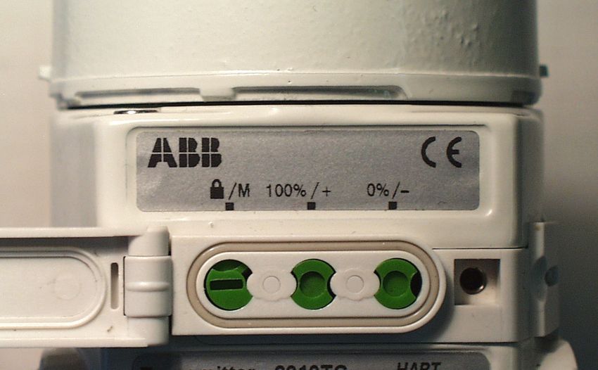
Another separate plate in front of the ”local” control unit shows the
functions of the three control elements by means of readily com-
prehensible symbols.
Additionally, a tie-on plate indicating the tag number may be at-
tached (optional).
Principle of operation and construction
The transmitter has a modular design and consists of the pressure
sensor module with an integrated electronic matching unit and an
amplifier with control unit. Depending on measuring range and
measured variable, either a ceramic pressure sensor or a silicon
pressure sensor is used. In case of the ceramic pressure sensor,
the applied process pressure (pe / pabs) is transferred directly to Figure 2. Transmitter 2020TA for absolute pressure
the measuring diaphragm, whereas, in case of the silicon pressure (Measuring ranges £ 400 mbar abs.)
sensor, the pressure is transferred via the separating diaphragm
and the fill fluid to the measuring diaphragm. When using the ce- In case of HARTâ / Bailey FSK devices, the output signal 4...20
ramic pressure sensor, a minimal deflection of the measuring dia- mA can be measured at the ”TEST” sockets without interrupting
phragm changes the output voltage of the pick-up system. In the the signal circuit (not applicable in case of fieldbus devices!).
silicon pressure sensor, the resistance values of four piezo-resis- A fixing possibility is provided for a stainless steel tie-on plate indi-
tors doped in the measuring diaphragm will change which causes cating the tag number.
a change of the output voltage. This pressure-proportional output Lower range value and upper range value can be set by means of
voltage is converted by means of the electronic matching unit and ”local” keys (optional, can be retrofitted) and, if required, the keys
the amplifier into an electrical signal. can be interlocked with the write protect switch.
Depending on the model, the transmitter is connected to the pro- The transmitter may be equipped with an LCD indicator which can
cess by means of a spigot G ½ (DIN EN 837), ½ - 14 NPT male or be read from the front (optional, can be retrofitted).
female thread, front-bonded diaphragm with special thread G ½ In conjunction with the LCD indicator, a complete external param-
for, e.g., ball valve connection or remote seal. eter setting and configuration of the transmitter is possible via the
The transmitter operates with a 2-wire system. The same wires are ”local” control unit (see section 7 ”Operation”).
used for the operating voltage (depending on the transmitter, see
section 10 ”Technical Data”) and the output signal (4...20 mA or Documentation
digital). The electrical connection is made via cable entry or plug. Supplementary documentation:
Instructions 42/15-710 EN
For device construction, detailed operation, assembly examples
08.2001 42/15-753-7 EN for 2020TG / 2020TA 3 of 244 Mounting creased Safety EEx e" according to the directions 94/9/EG (AT-
EX). Furthermore, the conditions stated in the type test certificate
of the cable gland have to be observed!
General
Before mounting the transmitter, check whether the model meets Note: If the type of protection ”Flameproof enclosure” (EEx d) ap-
the measurement and safety requirements of the measuring point, plies to the transmitter, the enclosure cover has to be locked by
e.g. with regard to materials, pressure rating, temperature, explo- means of the attachment screw (Fig. 3).
sion protection and operating voltage. The relevant recommenda- We would like to point out here that after intervals of several weeks
tions, regulations, standards and the rules for prevention of acci- an increased force is required to screw off the housing. This effect
dents must also be observed! (e.g. VDE/ VDI 3512, DIN 19210, is not caused by the thread but only due to the gasket type.
VBG, Elex V, etc.)
Measurement accuracy is largely dependent upon correct installa- Electrical connection in the cable connection compartment
tion of the transmitter and the related measurement piping. The
measuring set-up should be screened as much as possible from
critical ambient conditions such as major temperature variations,
vibration and shock. If unfavorable ambient conditions cannot be
avoided owing to reasons related to building structure, measuring
requirements or other reasons, this may influence the measure-
ment quality! (see section 10 ”Technical Data”).
If a remote seal with capillary tube is attached to the transmitter,
see also the Instructions 42/15-813 EN.
Transmitter
The transmitter can be connected directly onto the shut-off valve.
There is also a mounting bracket for wall or pipe mounting (2” pipe)
available as an accessory.
The transmitter should be installed preferably in a vertical position.
Please refer to section 11 ”Dimensional Diagrams” for possi-
ble mounting with bracket.
Measuring piping
The following points must be observed for correct installation:
• Keep the measurement piping as short as possible and avoid sharp
bends. Figure 3. Cable connection compartment
• Lay the measurement piping so that no deposits can accumulate. Electrical connection with plug
Gradients should not be less than 8 %.
• Measurement piping should be blown through with compressed air
or, better still, flushed through with the measuring medium before
connecting to the measuring element.
• Completely bleed measurement piping if the medium is a liquid.
• Lay the measurement piping so that gas bubbles, when measuring
liquids, or condensate when measuring gases, can flow back into the
process piping.
• Take care of the tightness of the connection.
5 Electrical Connection
The relevant guidelines must be observed during the electri- „barrel-type“ „DIN-type“
cal installation! Bild 4. Plug connection
Since the transmitter has no switch-off elements, overcurrent
protection devices or mains disconnection possibilities must Mounting of the socket connector
be provided on the system side. (Overvoltage protection at The socket connector for the cable connection is enclosed with the
option) transmitter for the plug version.
Check that the existing operating voltage corresponds to that indi-
cated on the type plate. Installation (see Fig. 5):
For power supply and output signal, the same lines are used. Con- The contact sockets (2) are crimped or soldered onto the cable
sult the enclosed connection diagram! ends (wire cross-section 0.75...1 mm²) from which 1.5...2 cm of the
Depending on the supplied model, the electrical connection is sheath and about 8 mm of the insulation has been removed and
made via cable entry 1/2-14 NPT or M 20 x 1.5 or via plug Han 8 U. inserted from the rear into the contact insert (1). The screwed
The screw terminals are suitable for wire cross-sections up to 2.5 gland (5), thrust ring (7), sealing ring (4) and grommet housing (3)
mm2. must be pushed onto the cable in the specified order prior to instal-
Caution: For transmitters of category 3 regarding the application lation (the sealing ring (4) may have to be adapted to the cable di-
in "Zone 2" the cable gland has to be provided by the customer. For ameter first).
this purpose there is a thread of size M 20 x 1.5 in the electronic
housing. The cable gland must comply with the protection type "In-
4 of 24 42/15-753-7 EN for 2020TG / 2020TA 08.2001Attention:
Check the connecting points again before pressing the sockets all
the way into the contact insert. Incorrectly installed sockets can
only be removed again with a special removal tool (item no.: 0949
813).
A connection terminal is available for grounding (PE) on the trans-
mitter exterior and also in the plug. Both terminals are electrically
interconnected.
Figure 6. Communication mode: "point-to-point"
Figure 5. Mounting of the socket connector
Protective conductor / grounding
The transmitter operates within the specified accuracy with com-
mon mode voltages between the signal lines and the housing up to
250 V.
On principle the power supply of the transmitter with an output volt-
age of max. 60 VDC has to be effected from a voltage source
which is safely separated from mains. In order to fulfill the require-
ments of the low-voltage guidelines and the relevant EN 61010
rules for the installation of electrical components, the housing must
be provided with a protective circuit (e.g. grounding, protective
conductor) if voltages of > 60 V could occur.
Set-up of the signal circuit / communication circuit for trans-
mitters with 4...20 mA output signal (HARTâ / Bailey FSK pro-
tocol) Figure 7. Communication mode: "FSK bus"
The transmitter can be operated via a modem by means of a PC
or laptop. The modem can be connected in parallel to the transmit- Notes on connecting cable
ter at any place in the signal circuit. Communication between To allow communication between transmitter and PC/laptop, ca-
transmitter and modem is made via AC signals which are overlaid bling must meet the following requirements:
to the analog 4...20 mA output signal. This modulation is effected It is recommended to use shielded and twisted pair lines.
without averaging and therefore, it does not influence the measur- The minimum wire diameter should be:
ing signal. - 0.51 mm for lines up to 1500 m
Communication between transmitter and PC or laptop is only pos- - 0.81 mm for lines longer than 1500 m
sible if the signal circuit is set up as shown in Fig. 6. The resistance The maximum line length is limited to:
between the connecting point of the FSK modem and the power - 3000 m for twin-core cable
supply must be at least 250 ohm including the internal resistance - 1500 m for multicore cable
of the supply unit. If this value is not reached with the normal instal-
lation, an additional resistance must be used. The actually possible line length of the electric circuit depends on
The additional resistance has already been installed by the manu- the total capacitance and joint resistance; it can be estimated ac-
facturer in the supply units TZN 128 and TZN 129. cording to the following formula:
In the ”FSK bus” mode, the TZN 128 allows to communicate direct-
ly via the supply unit. 6
65 ´ 10 C f + 10000
For power supply, either supply units, batteries or power packs can L = -------------------- – --------------------------
R´C C
be used which must be designed to ensure that the operating volt-
age UB of the transmitter is always between 10.5 and 45 V DC (for L = Line length in m
LCD indicator 14 ... 45 V DC). R = Joint resistance in
The max. current of 20... 22.5 mA which may occur by overranging C = Line capacitance in pF
according to the respective parameter setting, must be taken into Cf = Capacitance of the devices existing within the circuit
account. The minimum value for US results from this. If further sig- The shield should be grounded on one side only.
nal receivers (e.g. indicators) are connected into the signal circuit, Laying together with other electric circuits (with inductive load, etc.)
their resistance must also be taken into account. and the proximity of large electrical installations should be avoided.
08.2001 42/15-753-7 EN for 2020TG / 2020TA 5 of 24Max. permissible residual ripple of the supply voltage during com- Transmitters of the type of protection “flameproof enclosure
munication: EEx d” according to the directions 94 / 9 / EG (ATEX):
7 Vss at 50 Hz £ f £ 100 Hz ● It is not permitted to open the housing during operation
1 Vss at 100 Hz < f £ 200 Hz (operating voltage switched on)!
0.2 Vss at 200 Hz < f £ 300 Hz ● The following set-up instructions have to be observed:
1. The transmitter has to be connected via suitable cable and line
Notes on PROFIBUS-PA transmitters entries or piping systems which meet the requirements accord-
Fieldbus transmitters are provided for the connection to segment ing to EN 50 018:1994, Section 13.1and/or 13.2 and for which
couplers DP/PA. The permissible terminal voltage ranges from a separate test certificate is available!
10.2... 32 V DC. Current consumption is 14 mA (at average trans- 2. Unused openings of the housing have to be closed according
mission). to EN 50 018:1994, Section 11.9!
A shielded cable is recommended. Contacting of the shield is ef- 3. Cable and line entries as well as blanking plugs which do not
fected in the metal screwing. The transmitter must be grounded. correspond to the points 1. and 2. must not be used!
The transient behavior corresponds to the draft DIN IEC 65C / 155 ● To align the transmitter (torsion by max. 360°) at the measuring
/ CDV dated June 1996. When operating with an Ex-segment cou- point, the rotatable housing can be loosened at the shaft be-
pler according to DIN EN 61 158-2 October 1994, the max. number tween sensor and housing:
of devices may be reduced by a time-dependent current limitation. - Release the attachment screw by max. 1 rotation.
The output signal of the transmitter is transferred digitally accord- - Align the housing.
ing to IEC 61158-2. For PROFIBUS-PA, the communication proto- - Retighten the attachment screw!
col corresponds to Version 3.0, Class B, Ident-No.: 04C2 HEX (EN ● Before switching on the operating voltage:
50 170). - Close the housing.
During cyclic data traffic, the OUT variable is transmitted. It is com- - Secure enclosure cover by turning the attachment screw
posed of the output value and 1 byte status information. The output (hexagon socket screw) to the left.
value is transmitted with 4 bytes as IEEE-754 Floating-Point-Type. - Protect housing from torsion by turning the attachment
Further notes on PROFIBUS-PA, e.g. with respect to the "Ident screw (stud) to the right.
Number", are given in the "Additional Instructions 42/15-712- ● Enclosure cover, electronic housing and sensor may only be
Z0.20", the data sheet "Installation Suggestions 10/63-0.40" as replaced by approved components!
well as under the Internet address http://www.profibus.com.
Type test certificate / Conformity statement
Notes on explosion protection For transmitters in explosion-proof design the EC type test certifi-
For the installation (electrical connection, grounding / potential cate and / or the conformity statement have to be considered as
equalization, etc) of explosion-proof transmitters, the national stat- part of these operating instructions.
utory orders, DIN/VDE rules, guidelines for explosion protection
and the explosion proofness test certificate of the device have to
be observed. The certified explosion proofness of the transmitter is
indicated on the type plate.
Transmitters of the type of protection ”Intrinsically safe
EEx i” according to the directions 94 / 9 / EG (ATEX):
● Install only intrinsically safe devices within the transmitter sig-
nal circuit.
● The signal circuit may be interrupted even when the transmitter
is in operation (e.g. disconnect and connect signal lines).
● The housing may be opened during operation.
● Transmitters with and without remote seal of the protection type
"Intrinsically Safe EEx i" and ranges 60 / 400 mbar may be in-
stalled directly at Zone 0 if the power supply is effected via an
intrinsically safe circuit EEx ia.
● Transmitters with and without remote seal of the protection type
"Intrinsically Safe EEx i" and ranges ³ 2.5 bar may be installed
directly at Zone 0 ifthe power supply is effected via an intrinsi-
cally safe circuit EEx ia or EEx ib.
● Test circuit (terminals "TEST +/-"): in protection type Intrinsical-
ly Safe only for connection to passive intrinsically safe circuits.
The category, the explosion class as well as the max. values
Uo, Io and Po of the intrinsically safe test circuit are determined
by the connected intrinsically safe signal circuit. The rules for
interconnection have to be observed!
Transmitters of category 3 for the application in "Zone 2" ac-
cording to the directions 94 / 9 / EG (ATEX):
● The transmitter has to be connected via the approved cable
gland (protection type "Increased Safety EEx e" according to
ATEX).
● It is not permitted to open the housing during operation
(operating voltage switched on)!
6 of 24 42/15-753-7 EN for 2020TG / 2020TA 08.20016 Commissioning Note: The transmitter must have reached its operating tempera-
ture (approx. 5 min after switch-on if the transmitter has already as-
sumed ambient temperature) in order to be able to carry out the
After installing the transmitter, it is placed into operation by switch-
zero check. The correction has to be made at pe = 0 / pabs = 0 !
ing on the operating voltage.
There are two possibilities (point 1A or 1B) to perform the 4...20
● Check the following before switching on the operating voltage:
mA-output signal correction directly at the transmitter (control
- Process connections.
unit is available):
- Electrical connections.
1A. Apply pressure at lower range value (4 mA) – from the process
- That the measurement piping and measuring chamber of the
or from a pressure pick-off. The pressure must be stable and
transmitter are completely filled with the medium.
applied with high accuracy 20 mA may also indicate that the micro-
● Push the lock completely out of the push button unit, e.g. by
processor has detected an internal error; standard setting: 21 mA.
means of a suitable screw driver.
Via the communication tool SMART VISION, an exact diagnosis of
● Remove the uncovered square nut from the push button unit.
the error can be performed. A short-time interruption of power sup-
● Loosen the fixing screw of the push button unit by a Torx screw
ply results in an initialization of the electronic (restart of the pro-
driver (size T10) and pull the latter out of the electronic housing.
gram).
● If necessary, insert a spacer and tighten it by the attached
screw.
Write protection
Write protection prevents an illegal overwriting of the configuration Lock
data. If write protection is activated, the function of the keys 0 %
and 100 % is disabled. However, it is still possible to read out the Square nut
configuration data by means of SMART VISION (or another com- below which
parable communication tool). the fixing screw
If necessary, the control unit can be leaded. of the push button
Write protection is activated as follows (see also symbolism on the unit is located
plate):
1. First, fully press down the switch with an appropriate screw
driver.
2. Then turn the switch clockwise by 90 °Ð.
For deactivation the switch has to be pushed down a little and
Figure 8. Push button unit - disassembly / assembly
turned counterclockwise by 90 °Ð.
Mount LCD indicator
Oblique sensor/ zero correction
● Unscrew enclosure cover of the electronic compartment (see
During the installation of the transmitter, zero shifts (e.g. additional
figure 9) (if necessary, observe section ”Secure enclosure co-
remote seals etc.) caused by mounting may occur which have to
ver for EEx d”).
be corrected.
08.2001 42/15-753-7 EN for 2020TG / 2020TA 7 of 24● Plug LCD indicator. Ventilation aperture for 2020TG with ranges £ 30bar
Depending on the mounting position of the transmitter, the LCD
indicator can be slipped on in four different positions; in this
way turns by ± 90° or ± 180° are possible.
Note: If the LCD indicator is backlit (option), there is a three-
core cable with plug on the back of the indicator.
Connect this plug with the three-pole plug strip in the electronic
compartment (see Fig. 8) before slipping on the indicator.
If there is a jumper on the 3-pole plug strip (in case of fieldbus
transmitters no jumper is existing), it has to be removed and
plugged into the “socket for jumper”.
● Fasten LCD indicator with both screws.
● Hand-screw the enclosure cover (if necessary, observe section
”Secure enclosure cover for EEx d”).
Ventilation
aperture
For measurement reasons it is necessary to apply atmospheric
pressure to the reference side of the pressure sensor. For this pur-
pose there is a ventilation aperture at the outside of the sensor
which is protected by a PTFE filter. Therefore, it has to be taken
care that the ventilation aperture is not covered (e.g. painting is not
allowed).
7 Operation
There is no protection against electric shock when the hous-
ing covers are open. Do not touch live parts.
Figure 9. Electronic compartment – LCD indicator mounting
Secure enclosure cover for EEx d
On the top right of the electronic housing front, there is an attach-
ment screw (hexagon socket screw, SW 3mm).
Figure 11. Key legend plate
Operation with
”local keys” (at the device) without LCD indicator
The retrofit / optional control unit comprises 2 keys for external ad-
justment of lower range value (0 %) and upper range value (100
%) and a write protect switch. There are no physical connections
through the housing for the keys and the switch.
Calibration
Figure 10. Secure enclosure cover Lower range value and span may be adjusted directly at the trans-
mitter via keys.
● Turn enclosure cover hand-tight into the housing. The transmitter has been calibrated by the manufacturer according
● Secure enclosure cover by turning the attachment screw to the to the order data. The set values for lower range and upper range
left. In doing so the screw must be unscrewed to the stop of the are indicated on the type plate.
screw head at the housing cover.
8 of 24 42/15-753-7 EN for 2020TG / 2020TA 08.2001Generally the following applies: In the following, some of the a.m. menu items are described in de-
The 1st pressure value (e.g. 0 mbar) is always assigned to the 4 tail.
mA signal and the 2nd pressure value (e.g. 400 mbar) always to the
20 mA signal. Notes on ”Parallel shift (OFFSET SHIFT)”
To readjust the transmitter, apply the pressure for the lower and This function performs a parallel shift of the characteristic so that it
upper range value to the sensor. Make sure that the measuring runs through a specified point. Thus, the output signal of several
limits are not exceeded. measuring devices which measure the same process variable, can
Pressure reducing stations with adjustable pressure and compar- be brought to the same value without carrying out calibration with
ative displays can be used as sensors. When connecting, take applied pressure.
care to avoid residual liquids (with gaseous test media) or air bub- On certain conditions, the function may be performed at any point
bles (with liquid test media) in the piping since they can cause er- of the characteristic:
rors. ● Process variable within the adjusted measuring range
The pressure reducing station should have an accuracy of at least ● Transmitter with linear transfer function
3 times better than the transmitter to be tested.
It is advisable (adjusted time constant is known!) to set the damp-
ing to zero (via key plus LCD indicator or SMART VISION).
Regarding the 2020TA for absolute pressure with a measuring
ranges £ 400 mbar abs. it has to be observed that during transpor-
tation and storage the sensor has been overloaded by the atmos-
pheric pressure for a long time. Due to this, a starting time of ap-
prox. 3h is necessary after commissioning until the sensor is
stabilized so that the specified accuracy is kept.
Sequence of steps:
1. Apply pressure for lower range value and wait approx. 30 s
until it has stabilized.
2. Press key 0 % - output current is set to 4 mA.
3. Apply pressure for upper range value and wait approx. 30 s
Figure 12. Parallel shift
until it has stabilized.
Comments on Fig. 12:
4. Press key 100 % - output current is set to 20 mA.
By entering a percent value, an offset shift of the measuring range
5. If necessary, reset damping to the initial value.
is carried out.
6. Document new settings.
The transmitter displays with applied pressure px the standardized
10 s after the last actuation of the 0 % or 100 % keys, the respec-
output value x1 in percent. However, for the present application,
tive parameter is stored in a failsafe way.
the value x2 should be displayed. Now the value x2 is set via local
This procedure of adjustment only changes the 4...20 mA current
operation. The transmitter calculates the new zero and the new fi-
signal. The representation of the physical process pressure on the
nal value and then assumes these new settings.
digital display or by means of a communication tool, e.g. SMART
VISION, is not changed. To avoid this difference, a correction can Notes on “Damping (DAMPING)”
be made via the communication tool SMART VISION and its menu A fluctuating output signal of the transmitter, caused by the proc-
path Calibrate_Pressure Measurement_Adjust Input. ess, can be electrically smoothed (damped).
After such a correction, the calibration of the device must be The additional time constants is adjustable between 0 sec. and 60
checked. sec. in stepwise of 0.001s.
The damping set in this way does not affect the digitally indicated
Operation with value in physical units, only the derivatives such as analogue out-
”local keys” (at the device) with LCD indicator put current, free process variable, input signal for controller etc.
In conjunction with an LCD indicator, the transmitter can be config- Notes on “Characteristic (FUNCTION)”
ured with the keys ( - / + / M) as follows: In this menu option you can select the functions: linear and freely
(Note: Indications in ( ) designate the menu item, they are shown programmable. The “individuel values of the freely programmable
in the 1st and 2nd line of the indicator.) characteristic” cannot be changed here. A Hand-Held-Terminal or
• Exit the menu (EXIT) the communication tool SMART VISION has to be used for chan-
• View selected measured and calculated values (VIEW) ges.
• Lower range value with applied pressure (GET 0%)
Notes on “Fieldbus address (ADDRESS)
• Upper range value with applied pressure (GET 100%)
• Lower range value without applied pressure (SET 0%) Under this path, the fieldbus-slave-address may be changed. En-
• Upper range value without applied pressure (SET 100%) ter a figure between 0 and 126 for the selected transmitter.
• Correct zero drift (e.g. oblique sensor) (SHIFTZERO) Remark: Generally, the manufacturer assigns the address 126 to
• Parallel shift (OFFSET SHIFT) all new devices! The transmitters should get different addresses in
• Scaling output variable – initial value (OUT 0%) order to allow the addressing of a specific device. If, e.g., the de-
• Scaling output variable – final value (OUT 100%) vice data are loaded via the communication tool SMART VISION
• Damping (DAMPING) after the address has been changed, the connection set-up is ex-
• Output current in case of an error (ALARM CURRENT); only avail- ecuted again, and possibly an error message appears. Acknowl-
able for 4...20 mA devices with HARTâ or Bailey FSK protocol edge this with ”Repeat”, then the data will be loaded without any
• Displayed value (DISPLAY) problem.
• Pressure unit (UNIT)
• Temperature unit (UNIT) of internal temperature sensor
• Characteristic (FUNCTION) and the
• Fieldbus address (ADDRESS); only available for devices with
PROFIBUS-PA or FOUNDATION Fieldbus protocol.
08.2001 42/15-753-7 EN for 2020TG / 2020TA 9 of 24Measured value display
● The LCD indicator
Mode key(M)
2-line, 7-character, 19-segment alphanumeric display with addi-
tional bar chart display. Optionally the indicator is available with
back illumination.
Characters for: Protecting flat
- Transfer function, e.g. linear;
- Mode;
- Status
Keys (+) / (–)
Figure 14. Control elements (optional)
Display of the percent value
Display on LCD indicator
Unit (2nd line)
Bar chart to display the Current measured value 1st line Percent value, limits: -25% to 125%,
percent value (1st line) 2 decimal places
2nd line 1st position: Transfer function (Table 1)
2nd position: Write protection (Table 1)
Figure 13. LCD indicator (optional)
7th position: %
● Display of the physical value Bar chart 2% steps - from -2% to +10%,
At the first position of the first line, the sign is displayed. The following no hysteresis
six positions show the amount of the measured value. The comma is Table 2: Percent value display on LCD indicator
placed in such a way that the maximum value can be displayed with
these six positions. The place of the comma is not changed. A comma
at the sixth position is not displayed. Thus it is possible to display max.
+/-999999. If this value is exceeded Overflow . is indicated. In the
second line, the unit is displayed with the last five positions.
The first position shows the following characters, if necessary, one
after the other. Display changes every second.
Display for Character Comment
Transfer function , m or / Always one of these
characters appears.
Write protection s Only if write protection has
been set.
Cyclic ¸ Only in case of
communication PROFIBUS-PA
Status available ¦ Only if a status is available.
(e.g.measuring range
infringement or hard-
ware error)
Code of 1...9 See menu Display
displayed value (see structure tree)
Transmitter is Ë This character overwrites
busy other characters.
Table 1: Legend
10 of 24 42/15-753-7 EN for 2020TG / 2020TA 08.2001Program control To make the keys accessible, release the screw and turn the protection cap aside (see Figure 13). With the mode key "M", you can start menu-controlled program- ming. To call the next menu item, press the key "+". You will return via the key "- ". Sub- menu items / selection lists are activated via the mode key "M". A numerical value can only be changed via the keys "+" and " - ". It must be taken into account that the key "+" changes the value (each keystroke increases the value by 1), whereas the po- sition of the value to be changed is reached via the key " - ". Acknowledge changes with the mode key "M"; the subsequent OK ac- knowledgement (via the key "M", "+" or "-") writes the new value into the failsafe stor- age. An adjusting process can be aborted by pressing simultaneously the keys "+" and "-". From any main menu item, you can return to the menu item "EXIT" by simulta- neously pressing the "+" and "-" keys. When the adjustment has been finished, quit the program via the menu item "EXIT". By means of the following structure tree, you will get an overview of the selection / programming possibilities. Figure 15. Structure tree 08.2001 42/15-753-7 EN for 2020TG / 2020TA 11 of 24
Operation with PC / Laptop or Handheld terminal                        Operation via SMART VISIONâ
To configure the transmitter via PC / laptop, the software SMART       System requirements
VISION is required. Please refer to the software description for op-   ● SMART VISIONâ
erating instructions.                                                      SMART VISIONâ as from Version 4.00.31
                                                                           When installing the DTM (Device Type Manager),
Communication protocol: PROFIBUS-PAÒ or                                    SMART VISIONâ is updated to Version 4.00.43.
                        Foundation FieldbusÒ or                        ● Operating systems
                        HARTÒ or Bailey FSK                                · Windows NT 4.0
Hardware:               for HARTÒ and Bailey FSK:                          · Internet Explorer as from Version 5.0
                        FSK modem for PC / notebook                    Note:
Handheld Terminal:      STT 04 or HHT 275                              The DTM is started by means of the right mouse button or via the
                                                                       menu item "Device" with "Edit". After a "Connection setup", first the
                                                                       data of the 2020TG/TA should be loaded completely. Changed
                                                                       data are underlined and displayed in blue. These data are trans-
                                                                       mitted to the device via "Store data in the device".
                                                                       After the data have been saved in the transmitter, their nonvolatile
                                                                       storage is effected automatically. To do this, power supply to the
                                                                       transmitter must be continued for 2 minutes. If this is not observed,
                                                                       the previous data will become active again during the next opera-
                                                                       tion. In case of software versions < 0.20 (< 20 for HART), storage
                                                                       will only be effected after disconnection.
                                                                       For Profibus devices, the disconnection of "Local operation" only
                                                                       becomes effective in case of cyclic communication. If write protec-
                                                                       tion is set by means of the DTM, the setting of the 2020TG/TA can
                                                                       no more changed via the control keys.
                                                                       For Profibus devices, the slave address must be indicated correct-
                                                                       ly in the project tree of SMART VISIONâ. Communication name
                                                                       and description are automatically updated when loading the device
                                                                       data.
                                                                       The most important calibration / parameterization possibilities un-
           Figure 16. Communication set-up via STT04                   der SMART VISIONâ are shortly described in the following. You
                                                                       will find further notes on the menu items in the context-sensitive
Configuration of the flow measurement with SMART VISION                help. Before carrying out any setting, please ensure that write pro-
If the transmitter has been configured at the manufacturer's work      tection has neither been activated on the transmitter itself (key s )
for the measuring point according to the specifications given in the   or via SMART VISIONâ(menu path Configuration_Basic Para-
questionnaire you do not have to do anything else than to assem-       meters _General _Local Operation).
ble the transmitter as specified (perhaps correct the oblique sensor
-refer to command: Configure_Pressure Measurement_Pro-                 ● Adjust damping
cess Variable (Oblique Sensor)). After switch on the measuring           Menu path:
point is ready for operation. If the transmitter is equipped with an     Configuration_Pressure Measurement_Output
LCD indicator, the current differential pressure (default adjust-        The required value has to be entered in the field "Output para-
ment) is displayed immediately.                                          meters" in the line "Damping".
However, it you want to make changes e.g. concerning the config-       ● Correct oblique sensor
uration of the mass flow measurement, you need a communication           Menu path:
tool, e.g. SMART VISION. By means of this tool the device can be         Configuration_Pressure Measureent_Process Variable
configured completely. It supports the HART Protocol as well as          Actuate the button  in the field "Oblique sensor-
the fieldbus protocols "PROFIBUS-PA and FOUNDATION Field-                ment". Balancing is immediately effected with nonvolatile stora-
bus" and is operable on a PC / Notebook and/or in an automation          ge in the transmitter.
system.                                                                ● Adjust lower and upper range value
The necessary operating steps for the installation of SMART VISI-        Menu path:
ON are described in the installation instructions delivered with the     Configuration_Pressure Measurement_Process Variable
software. The parameters can be adjusted via the path Configu-           In the field "Scaling", the adjustment is possible in two ways:
re_Pressure Measurement.                                                 - Value input: The required value / values has / have to be en-
The program offers the possibility to configure, to set parameters,        tered in the input fields "Lower range value" and / or "Upper
to interrogate and to test the devices. Furthermore an OFF-line            range value".
configuration can be carried out via an internal data management.        or
Every parameter setting and configuration is subjected to a plausi-      - Process pressure acceptance: For the adjustment, the
bility check.                                                              lower range value and the upper range value are preset as
The  key provides extensive context-sensitive help at every            pressure at the sensor. Make sure that
stage throughout the complete program.                                     the measuring limits are not exceeded. Pressure reducing
Attention: Immediately after the delivery of the transmitters and/or       stations with adjustable pressure and comparative displays
before changing the configuration we recommend to save the ex-             can be used as sensors. When connecting, take care to avoid
isting configuration data on a data medium using the command               residual liquids (with gaseous test media) or air bubbles (with
File_Save.                                                                 liquid test media) in the piping since they can cause errors.
                                                                           The pressure reducing station should have an accuracy of at
                                                                           least 3 times better than the transmitter to be tested.

12 of 24                                          42/15-753-7 EN for 2020TG / 2020TA                                               08.2001
8 Maintenance Spans
The adjusted span must not be lower than the minimum range.
Measuring ranges
The transmitter is maintenance-free.
Code min. max.
It is sufficient to check the output signal – depending on the oper- B 200 Pa / 2 mbar 6 kPa / 60 mbar
ating conditions - at regular intervals according to section 7 ”Oper- C 400 Pa / 4 mbar 40 kPa / 400 mbar
ation”. D 2.5 kPa / 25 mbar 250 kPa / 2.5 bar
If deposits in the sensor are to be expected, the sensor should also F 30 kPa / 0.3 bar 3 MPa / 30 bar
be cleaned at regular intervals – depending on the operating con- G 100 kPa / 1 bar 10 MPa / 100 bar
H 600 kPa / 6 bar 60 MPa / 600 bar
ditions. Cleaning should preferably be carried out in the workshop. K 200 Pa / 2 mbar abs. 6 kPa / 60 mbar abs.
If a remote seal is attached to the sensor, it must not be dismoun- L 400 Pa / 4 mbar abs. 40 kPa / 400 mbar abs.
ted! M 2.5 kPa / 25 mbar abs. 250 kPa / 2.5 bar abs.
Replace defective transmitters/units according to the "Parts Data O 20 kPa / 0.2 bar abs. 2 MPa / 20 bar abs.
Sheet".
Output signal
Transmitters with 4...20mA
9 Repairs Signal: analogue 4 ... 20 mA
Output signal limits: Imin = 3.5 mA, Imax = 22.5 mA
Attention: Explosion-proof transmitters may only be repaired by (configurable).
the manufacturer, or they must be certified by an acknowledged Standard setting: Imin = 3.8 mA, Imax = 20.5 mA
expert after the repair has been carried out!
Alarm current
Observe the pertinent safety regulations before, during and after
commissioning. Min. alarm current: configurable from 3.5 mA to 4 mA,
Disassemble the transmitter only to such extent as necessary for standard setting: 3.6 mA
cleaning, checking, repairing and replacing the defective parts. Max. alarm current: configurable from 20 mA to 22.5 mA,
Observe section 8 "Maintenance"! standard setting: 21 mA
Sensor as well as sensor with attached remote seal can only be re- Standard setting: max. alarm current
paired by the manufacturer. Load
If the electronic housing has to be detached from the sensor / the Transmitters with 4...20 mA
measuring cell, the electronic unit must be removed from the elec-
tronic housing before in order to prevent a damage to the electron- R £ Us – 10, 5V
-------------------------------
I
in kOhm
ic unit. For this purpose, first of all the housing cover has to be max
screwed off (attachment screw!, refer to figure 10), then remove a Imax = 20 ... 22.5 mA (configurable)
possibly existing LCD indicator from the electronic unit (loosen 2 Us = supply voltage
screws), unscrew the two captive screws of the electronic unit and min. power supplyy: 10.5 VDC, 14 VDC with backlit LCD-indicator
remove same carefully from the electronic housing. Detach the two min. load for digital communications > 250 Ohm
plugs from the electronic unit (both plugs have got a mechanical Field Bus units
reverse battery protection and the smaller one additionally a me- Signal: digital
chanical interlock: seize the plug on the front side between thumb Transmission technique: acc. to IEC 61158-2
and forefinger and press the lock towards the plug, then pull off the Power supply: 10.2 VDC ... 32 V DC
plug from the socket). Put the electronic unit on a suitable pad. Un- Base current: 14 mA
screw the electronic housing from the sensor / the measuring cell. Transmission rate: 31.25 kbits/s
PROFIBUS-PA: Version 3.0, Profile B for pressure
Return transmitters; Ident No.: 04C2 HEX
Defective transmitters/units are to be sent to the repair depart- Foundation Fieldbus: FF-890 / 891 ans FF-902 / 903
ment, if possible stating the fault and its cause.
Characteristic
Note: When ordering spare parts or instruments, please quote the
Linear, freely programmable with 20 reference points
serial number (F.-No.) of the original transmitter.
Accuracy
Address: Reference conditions
ABB Automation SystemsGmbH to DIN IEC 770
Department SWM Temperature: 20 °C
Schillerstraße 72 Relative humidity: 65 %
D-32425 Minden Atmospheric pressure: 1013mbar (1013 hPa)
additional conditions:
Characteristic „linear output“ and transmitter with silicon pressure
10 Technical Data sensor: separating diaphragm material “Hastelloy C“, fill fluid “sili-
cone oil”
All specifications are limits and relate to the output range or cali-
Measured value brated range. The influences marked * relate to the measuring
2020TG: Gauge Pressure range (URL) and are to be multiplied by the turn down factor (ratio
2020TA: Absolute Pressure range (URL) / calibrated span). The turn down factor should be
Measuring range (upper and lower range values) kept to a minimum.
Lower range value (continuously adjustable) Conformity
2020TG: - 100% (³ -1bar) to + 100% of the URL 0.075 % 1)
2020TA: 0% and + 100% of the URL terminal based, including hysteresis and the dead band (optional
Upper range value (continuously adjustable) 0.05 %)
Up to 100% of the URL
08.2001 42/15-753-7 EN for 2020TG / 2020TA 13 of 24Reproducibility Electromagnetic compatibility (EMC)
0.01 % to EN 50 082-2
Hysteresis Definition: Class 3
0.05 % Radio suppression (EN 55 011): Limit class B
Fulfills NAMUR recommendation.
Warm-up time
Process conditions
< 15 s
Temperature limits
Rise time
-50 °C ... +120 °C, at process connection
The time behaviour of this transmitter is composed of the rise time to +400 °C in conjunction with remote seal.
of the sensor and an adjustable integration time constant of the with O-rings ranges: 60 mbar and 400 mbar)
A/D converter. A high time constant results into a high resolution, · Viton (fluorocaoutchouc (FPM)) -20 °C ... +120 °C
e.g. required for a high span ratio, and at the same time into a high- · Perfluorelastomer (º PTFE): -15 °C ... +80 °C
er rise time for the output signal. A low time constant means a low-
er resolution, but a shorter rise time and thus a faster reaction time Pressure limits
of the transmitter. In case of the default integration time constant from vacuum up to maximum span
the values shown in the table below result. Overload limit
freely programm- Ranges £ 400 mbar: 10 bar
linear
able function · with O-ring perfluorelastomer: 6 bar abs.
turn down factor Ranges 2.5 bar ... 100 bar: 2 x times
the range end value
> 1 : 10 > 1 : 20 Range 600 bar: 900 bar
£ 1 : 10 up to up to > 1: 40
£ 1 : 20 £ 1 : 40 Weight
1.2 kg
~ 0.3 s ~ 0.5 s ~ 0.9 s ~ 1.4 s ~ 0.5 s
Material
additional adjustable time constant 0...60s
Process connection: 316 L stainless steel * / Hastelloy C *
Diaphragm: Ceramic (Al2O3) - gold plated /
The effect appearing at the output for non-linear output depends
on the function and is to be calculated accordingly. Hastelloy C /
Long-term drift Hastelloy C - gold plated
Fill fluid: ranges ³ 2.5 bar:
* 0.05% per 12 months
Silicone oil / carbon fluoride /
Ambient temperature effect white oil (corresponds to re-
Thermal change (-40°C ... +80°C)2) quirements of the US Food
* on zero 0.1 % and Drug Administration (FDA):
on span 0.1 % 21CFR172.878 and
Temperature coefficient (-40°C ... +80°C)2) 21CFR178.3620)
* on zero 0.04 % per 10°C O-rings: ranges £ 400 mbar:
on span 0.04 % per 10°C Viton(FPM) / Perbunan(NBR)/
Effect of electro-magnetic interference Chemraz 505 * (medium resistivety
* 0.05% comparable to PTFE)
Amplifier housing / aluminium with epoxy resin coat /
1)
additionally with turn-down factor > 1:10 Housing cover: stainless steel
measuring range
± ( 0.005 ´ ------------------------------------------ – 0.05 ) % * in compliance with NACE MR0175 Class II
adjusted span
2) Process connection
with carbon fluoride filling liquid: -20 °C ... +80 °C
Male thread / female thread 1/2-14 NPT or male thread acc. to DIN
Ambient conditions
EN 837 - form B - G 1/2 (R 1/2“ manometer) or male thread acc. to
Ambient temperature DIN EN 837 - form D - G 1/2 (R 1/2“ manometer) for convex seal
-40 °C ... +85 °C (with O-ring Viton: -20 °C ... +85 °C), or frontbonded diaphragm ( not for ranges 60 mbar and 400 mbar).
Observe approvals for explosion-protected transmitters.
Electrical connections
Storage temperature / transport temperature Two female threads 1/2-14 NPT or M 20 x 1.5 or one plug Han 8 U.
-50 °C ... +85 °C, with LCD-indicator -40 °C ... +85 °C Screw terminals for wire cross-sections up to 2.5 mm2.
Humidity Power supply
Relative humidity: £ 95% annual average Transmitters with 4...20mA output signal
Condensation, icing: admissible Power supply: 10.5 ... 45 V DC (14 ... 45 V DC with backlit
Protection class indicator), inverse polarity protection;
IP 67 acc. to EN 60 529 (=NEMA Standard Type 6); observe the approvals for explosion-proof
with Han 8U plug: IP 65 (=NEMA Standard Type 4X) transmitters.
Protective varnish Residual ripple: Max. permissible residual ripple of
supply voltage during the communication:
epoxy resin, greywhite, RAL 9002
· 7 Vss at 50Hz £ f £ 100Hz
Shock resistant · 1 Vss at 100Hz < f £ 200Hz
Acceleration: 50g · 0.2 Vss at 200Hz < f £ 300Hz
Duration: 11ms
Fieldbus units
Vibration resistance Power supply: 10.2 ... 32 V DC, inverse polarity protection;
2g up to 1000 Hz, with amplifier housing made of “stainless steel” observe the approvals for explosion-proof
are valid restricted values (on request) transmitters.
14 of 24 42/15-753-7 EN for 2020TG / 2020TA 08.2001Pollution degree Permissible ambient temperature range in dependence on
2 according to EN 61 010-1 (ANSI / ISA 82.01) temperature class:
Overvoltage category
Ambient Ambient
II according to EN 61 010-1 (ANSI / ISA 82.01)
Temperature class temperature temperature
Certificates and Approvals minimum maximum
Observe mounting conditions according to EN 60079-10; 1996ff!
-40 °C +85 °C
Transmitters of the type of protection ”Intrinsically safe T4
-104 °F +185 °F
EEx ia” according to the directions 94 / 9 / EG (ATEX)
● Transmitter with 4...20 mA output signal -40 °C +40 °C
T5
Marking (DIN EN 50 014): II 1/2 G EEx ia IIC T6 -104 °F +104 °F
EC-Type-Examination Certificate: ZELM 01 ATEX 0064 -40°C +40 °C
Supply and signal circuit type of protection Intrinsic Safety T6
-104 °F +104 °F
EEx ib IIB / IIC resp. EEx ia IIB / IIC for connection to supply
units with maximum values:
II 1/2 G EEx ia IIC T4 ... T6, Transmitters of the type of protection ”flameproof enclosure
for Temperature class T4: EEx d” according to the directions 94 / 9 / EG (ATEX)
Ui = 30 V Marking (DIN EN 50 014): II 1/2 G EEx d IIC T6
Ii = 200 mA EC-Type-Examination Certificate: PTB 00 ATEX 1018
Pi = 0,8 W for T4 with Ta = (-40...+85)°C / (-104...+185)°F Ambient temperature range: -40 °C ... 75°C
Pi = 1,0 W for T4 with Ta = (-40...+70)°C / (-104...+158)°F (-104°F ... 167°F)
for Temperature class T5, T6: Transmitters of category 3 for the application in "Zone 2" ac-
Ui = 30 V cording to the directions 94 / 9 / EG (ATEX)
Ii = 25 mA Marking (DIN EN 50 014): II 3 G EEx nL IIC T6
Pi = 0,5 W for T6 with Ta = (-40...+40)°C / (-104...+104)°F EC-Type-Examination Certificate: ZELM 01 ATEX 3059
Pi = 0,75W for T5 with Ta = (-40...+40)°C/(-104... +104)°F Operating conditions:
Supply and signal circuit
effective internal capacitance Ci £ 10 nF, (terminals signal + / -): U £ 55 V
effective internal inductivity Li » 0 U £ 22.5 mA
Ambient temperature range:
Permissible ambient temperature range in dependence on Temperature class T4 Ta= -40 °C ... 85 °C
temperature class: (-104°F ... 185°F)
Temperature class T5, T6 Ta= -40 °C ... 40 °C
Ambient Ambient (-104°F ... 104°F)
Temperature class temperature temperature
minimum maximum Factory Mutual (FM) (pending)
Intrinsically safe,
-40 °C +85 °C
T4 Explosion-Proof: Class I, Division 1, Groups A, B, C, D
-104 °F +185 °F
Class II/III, Division 1, Groups E, F, G
-40 °C +40 °C Degree of protection: NEMA Type 4X (Indoor or outdoor)
T5
-104 °F +104 °F
Canadian Standard (CSA) (pending)
-40°C +40 °C
T6 Intrinsically safe,
-104 °F +104 °F
Explosion-Proof: Class I, Division 1, Groups A, B, C, D
Class II, Division 1, Groups E, F, G
● Field Bus transmitters (PROFIBUS / Foundation Fieldbus) Class III
Marking (DIN EN 50 014): II 1/2 G EEx ia IIB/IIC T6 Degree of protection: NEMA Type 4X (Indoor or outdoor)
EC-Type-Examination Certificate: ZELM 01 ATEX 0063
Supply and signal circuit type of protection Intrinsic Safety
EEx ib IIB / IIC resp. EEx ia IIB / IIC for connection to FISCO
supply units with rectangular or trapezoidal characteristics with
maximum values:
II 1/2G EEx ia respectively ib IIC T4...T6 Ui = 17.5 V
li = 360 mA
Pi = 2.52 W
II 1/2G EEx ia respectively ib IIB T4...T6 Ui = 17.5 V
li = 380 mA
Pi = 5.32 W
resp. for connection to supply unit or barrier with linear charac-
teristics maximum values:
II 1/2G EEx ia respectively ib IIC T4...T6 Ui = 24 V
li = 250 mA
Pi = 1.2 W
effective internal inductance Li £ 10 µH,
effective internal capacitance Ci » 0
08.2001 42/15-753-7 EN for 2020TG / 2020TA 15 of 24You can also read