Satellite Imagery Product Specifications - Version 6.1 | April 2015
←
→
Page content transcription
If your browser does not render page correctly, please read the page content below
Satellite Imagery
Product Specifications

Version 6.1 | April 2015

                             www.blackbridge.com
                           rapideye@blackbridge.com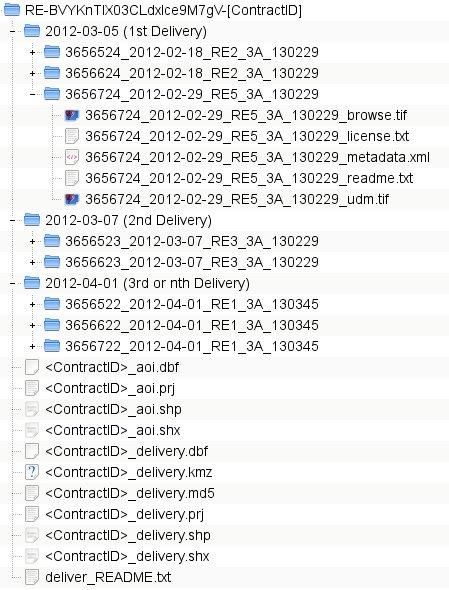
CONTENT
1        INTRODUCTION .......................................................................................................................................... 5
2        RAPIDEYE SATELLITE CONSTELLATION ........................................................................................................ 6
3        RAPIDEYE SATELLITE IMAGE PRODUCT SPECIFICATIONS ............................................................................. 7
         RapidEye Basic – Level 1B Product Specification ............................................................................................... 7
         RapidEye Ortho – Level 3A Product Specification .............................................................................................. 9
         RapidEye Ortho Take– Level 3B Product Specification ...................................................................................... 9
         Product Quality Attributes ............................................................................................................................... 10
3.4.1.    Geometric Product Accuracy ......................................................................................................................... 10
3.4.2.    Cloud Cover .................................................................................................................................................... 11
3.4.3.    Band Co-registration ...................................................................................................................................... 12
3.4.4.    Product Radiometry and Radiometric Accuracy ............................................................................................ 12
4        PRODUCT AND DELIVERY OPTIONS ........................................................................................................... 15
5        PRODUCT LICENSING ................................................................................................................................ 16
6        PRODUCT NAMING ................................................................................................................................... 17
         1B – Basic Product Naming .............................................................................................................................. 17
         3A – Ortho Product Naming ............................................................................................................................. 18
         3B – Ortho Take Product Naming .................................................................................................................... 19
7        PRODUCT DELIVERY .................................................................................................................................. 20
         Delivery Options............................................................................................................................................... 20
         Delivery Files .................................................................................................................................................... 20
7.2.1.    Delivery Readme File ..................................................................................................................................... 20
7.2.2.    Area of Interest (AOI) Shapefile ..................................................................................................................... 21
7.2.3.    Delivery Summary Shapefile .......................................................................................................................... 21
7.2.4.    Delivery Summary KMZ File ........................................................................................................................... 21
7.2.5.    Delivery Checksum File .................................................................................................................................. 22
         Delivery Folder Structure ................................................................................................................................. 22
8        IMAGE SUPPORT DATA ............................................................................................................................. 24
         General XML Metadata File ............................................................................................................................. 24
8.1.1.     Contents......................................................................................................................................................... 24
8.1.2.     File Naming .................................................................................................................................................... 30
         Spacecraft Information XML Metadata File ..................................................................................................... 30
8.2.1.     Contents......................................................................................................................................................... 30
8.2.2.     File Naming .................................................................................................................................................... 32
         Image RPC XML Metadata File ......................................................................................................................... 32
8.3.1.     Contents......................................................................................................................................................... 32
8.3.2.     File Naming .................................................................................................................................................... 33
         Browse Image File ............................................................................................................................................ 33
8.4.1.     Contents......................................................................................................................................................... 33
8.4.2.     File Naming .................................................................................................................................................... 33
         Unusable Data Mask File .................................................................................................................................. 34
8.5.1.     Contents......................................................................................................................................................... 34
8.5.2.     File Naming .................................................................................................................................................... 35
         License File ....................................................................................................................................................... 35
8.6.1.     Contents......................................................................................................................................................... 35
8.6.2.     File Naming .................................................................................................................................................... 35
         Readme File...................................................................................................................................................... 36
8.7.1.     Contents......................................................................................................................................................... 36
8.7.2.     File Naming .................................................................................................................................................... 36
APPENDIX A – GLOSSARY OF TERMS.................................................................................................................... 37

Satellite Imagery Product Specifications                                                                                                                               2
APPENDIX B – TILE GRID DEFINITION ................................................................................................................... 38 APPENDIX C – NITF FILE STRUCTURE AND CONTENTS .......................................................................................... 41 INDEX OF TABLES Table 1: RapidEye System Mission Characteristics........................................................................................................ 6 Table 2: RapidEye Satellite Image Product Processing Levels ....................................................................................... 7 Table 3: Product attributes for RapidEye Basic products .............................................................................................. 8 Table 4: Attributes for RapidEye Ortho Products .......................................................................................................... 9 Table 5: Attributes for RapidEye Ortho Take Products ............................................................................................... 10 Table 6: Product Processing and Delivery Options...................................................................................................... 15 Table 7: Product naming values for 1B products by category ..................................................................................... 17 Table 8: Product naming values for 3A products by category .................................................................................... 18 Table 9: Product naming values for 3B products by category ..................................................................................... 19 Table 10: Delivery Readme File Contents .................................................................................................................... 20 Table 11: General XML Metadata File Field Descriptions ........................................................................................... 24 Table 12: Spacecraft Information Metadata File Field Descriptions ........................................................................... 30 Table 13: Image RPC Metadata File Field Descriptions ............................................................................................... 32 Table 14: Readme File Contents .................................................................................................................................. 36 Table 15: NITF File Main Header Contents .................................................................................................................. 42 Table 16: NITF Subheader Contents ............................................................................................................................ 43 Table 17: RPC00B (Rapid Positioning Capability) portion of the NITF Subheader Contents ....................................... 46 Table 18: STDIDC (Standard ID Extension Format) portion of NITF Subheader Contents ........................................... 47 Table 19: USE00A (Exploitation Usability) portion of the NITF Subheader Contents ................................................. 48 INDEX OF FIGURES Figure 1: Expected Product Delivery Folder Structure for FTP Deliveries .................................................................. 23 Figure 2: Concepts behind the Unusable Data Mask file ............................................................................................ 35 Figure B-1 Layout of UTM Zones ................................................................................................................................. 38 Figure B-2 Layout of Tile Grid within a single UTM Zone ............................................................................................ 39 Figure B-3 Illustration of grid layout of Rows and Columns for a single UTM Zone .................................................... 40 Figure C-1: Structure of NITF 2.0 File .......................................................................................................................... 41 Satellite Imagery Product Specifications 3
ABBREVIATIONS

AOI                 Area Of Interest

CCD                 Charged-coupled Device

CE90                Circular Error 90%

DEM                 Digital Elevation Model

DTED                Digital Terrain Elevation Data

GCP                 Ground Control Point

GML                 Geography Markup Language

GS                  Ground Segment

IFOV                Instantaneous Field of View

ISD                 Image Support Data

JFIF                JPEG File Interchange Format

JPEG                Joint Photographic Experts Group

KML                 Keyhole Markup Language

MTF                 Modulation Transfer Function

N/A                 Not Applicable

NIR                 Near Infra-red

NMAS                National Map Accuracy Standards

NITF                National Imagery Transmission Format

RPC                 Rational Polynomial Coefficients or Rapid Positioning Coordinates

SRTM                Shuttle Radar Topography Mission

TBC                 To Be Confirmed

TBD                 To Be Defined

TIFF                Tagged Image File Format

TOA                 Top Of Atmosphere

TOI                 Time Of Interest

UDM                 Unusable Data Mask

UTC                 Coordinated Universal Time

UTM                 Universal Transverse Mercator

WGS                 World Geodetic System

Satellite Imagery Product Specifications                                                4
1 INTRODUCTION
Blackbridge offers image users a data source containing an unrivaled combination of large-area coverage, frequent
revisit intervals, high resolution and multispectral capabilities. For the first time, there is a constellation of five
earth imaging satellites that contain identical sensors that are in the same orbital plane and are calibrated equally
to one another. This means an image from one RapidEye satellite will be identical in characteristics to an image
from any of the other four satellites, thus allowing the user access to an unprecedented amount of imagery
collected on a frequent basis.

RapidEye Satellite Imagery Products are offered at three different processing types to support the varied needs of
the customer: 1) RapidEye Basic (Level 1B) products are sensor level products with a minimal amount of processing
(geometrically uncorrected) for customers who prefer to geo-correct the images themselves; and 2) RapidEye
Ortho (Level 3A) are orthorectified tile products with radiometric, geometric and terrain corrections in a map
projection; and 3)RapidEye Ortho Take (Level 3B) are orthorectified, bundle adjusted image takes that are larger
than the Level 3A products. See Section 3 for detailed descriptions of each image product type.

This document provides detailed information on the following subjects related to the RapidEye Satellite Imagery
Products:

RapidEye Satellite Constellation: The RapidEye constellation of 5 satellites offers something new and unique to
the world of commercial remote sensing.

Product Level Descriptions: Blackbridge offers three different processing levels for RapidEye Satellite images
which are described in detail. Attributes related to product quality are also discussed.

Product and Delivery Options: Each image data product is offered with several processing and delivery options.

Product Licensing: Blackbridge offers customers several licensing options to ensure that all users who need to use
the imagery may do so.

Product Naming: Provides a description of the product naming conventions used for the RapidEye Satellite
Imagery Products.

Product Delivery: The Satellite Image Products are delivered in a standardized format and structure. Orders can be
delivered via physical storage devices or electronically via FTP pull download. This section details what can be
expected regarding the files and structure of a data delivery.

Image Support Data: All images are supported with several different metadata files to aid the customer with the
use and analysis of the data.

Satellite Imagery Product Specifications                                                                         5
2 RAPIDEYE SATELLITE CONSTELLATION
The RapidEye constellation of five satellites stands apart from other providers of satellite-based geospatial
information in its unique ability to acquire high-resolution, large-area image data on a daily basis. The RapidEye
system is able to collect an unprecedented 4 million square kilometers of data per day at 6.5 meter nominal
ground resolution. Each satellite measures less than one cubic meter and weighs 150 kg (bus + payload), and has
been designed for a minimum seven-year mission life. All five satellites are equipped with identical sensors and are
located in the same orbital plane.

Table 1: RapidEye System Mission Characteristics
  MISSION CHARACTERISTIC                                   INFORMATION
   Number of Satellites                                    5

   Spacecraft Lifetime                                     Over 7 years

   Orbit Altitude                                          630 km in Sun-synchronous orbit

   Equator Crossing Time                                   11:00 am local time (approximately)

   Sensor Type                                             Multi-spectral push broom imager
   Spectral Bands                                          Capable of capturing all of the following spectral bands:

                                                           Band Name                         Spectral Range (nm)
                                                           Blue                              440 – 510
                                                           Green                             520 – 590
                                                           Red                               630 – 685
                                                           Red Edge                          690 – 730
                                                           NIR                               760 – 850
   Ground sampling distance (nadir)                        6.5 m

   Pixel size (orthorectified)                             5m

   Swath Width                                             77 km

   On board data storage                                   Up to 1500 km of image data per orbit

   Revisit time                                            Daily (off-nadir) / 5.5 days (at nadir)

   Image capture capacity                                  5 million km²/day

   Camera Dynamic Range                                    12 bit

Satellite Imagery Product Specifications                                                                               6
3 RAPIDEYE SATELLITE IMAGE PRODUCT
SPECIFICATIONS
RapidEye Satellite Imagery Products are available in three different processing levels to be directly applicable to
customer needs.
Table 2: RapidEye Satellite Image Product Processing Levels
LEVEL DESCRIPTION
1B RapidEye Basic Product - Radiometric and sensor corrections applied to the data. On-board
spacecraft attitude and ephemeris applied to the data.
3A RapidEye Ortho Product – Radiometric, sensor and geometric corrections applied to the data. The
product accuracy depends on the quality of the ground control and DEMs used. Product is
processed as an individual 25 km by 25 km tile.
3B RapidEye Ortho Take Product – Large-scale orthorectified product based on RapidEye Image
Takes. Multiple images over an AOI will be bundle adjusted together for accuracy purposes.
RAPIDEYE BASIC – LEVEL 1B PRODUCT SPECIFICATION
The RapidEye Basic product is the least processed of the available RapidEye image products. This product is
designed for customers with advanced image processing capabilities and a desire to geometrically correct the
product themselves.
The RapidEye Basic product is radiometric and sensor corrected, providing imagery as seen from the spacecraft
without correction for any geometric distortions inherent in the imaging process, and is not mapped to a
cartographic projection. The imagery data is accompanied by all spacecraft telemetry necessary for the processing
of the data into a geo-corrected form, or when matched with a stereo pair, for the generation of digital elevation
data. Resolution of the images is 6.5 meters GSD at nadir. The images are resampled to a coordinate system
defined by an ideal basic camera model for band alignment.
The radiometric corrections applied to this product are:
Correction of relative differences of the radiometric response between detectors
Non-responsive detector filling which fills nulls values from detectors that are no longer responding
Conversion to absolute radiometric values based on calibration coefficients
The geometric sensor corrections applied to this product correct for:
Internal detector geometry which combines the two sensor chipsets into a virtual array
Optical distortions caused by sensor optics
Registration of all bands together to ensure all bands line up with each other correctly
Table 3 lists the product attributes for the RapidEye Basic product.
Satellite Imagery Product Specifications 7Table 3: Product attributes for RapidEye Basic products
PRODUCT ATTRIBUTE DESCRIPTION
Product Components and RapidEye Basic image product consists of the following file components:
Format Image File – Image product delivered as a group of single-band NITF 2.0 or GeoTIFF
files with associated RPC values. Bands are co-registered.
Metadata File – XML format metadata file. Metadata file contains additional
information related to spacecraft attitude, spacecraft ephemeris, spacecraft
temperature measurements, line imaging times, camera geometry, and radiometric
calibration data.
Browse Image File – GeoTIFF format
Unusable Data Mask (UDM) file – GeoTIFF format
Product Orientation Spacecraft/sensor orientation
Product Framing
Geographic based framing – a geographic region is defined by two corners. The product width is close to the full image
swath as observed by all bands (77 km at nadir, subject to minor trimming of up to 3 km during processing) with a
product length of between 50 and 300 km.
N
N
Geographic Region defined
by two corners
Geographic Region defined
by two corners
Sensor Scanning Track
Sensor Scanning Track
Shaded Area is Output Image Shaded Area is Output Image
Geographic Perspecitive Image Perspecitive
Pixel spacing Native camera pixel spacing, nominally 6.5 m at nadir.
Bit Depth 16-bit unsigned integers.
Product Size Variable number of pixels (less than 11980 per line) and up to a maximum of 46154
lines per band.
462 Mbytes/25 km along track for 5 bands. Maximum 5544 Mbytes.
Geometric Corrections Idealized sensor, orbit and attitude models. Bands are co-registered.
Horizontal Datum WGS84
Map Projection n/a
Resampling Kernel Cubic Convolution (default), MTF, or Nearest Neighbor
Satellite Imagery Product Specifications 8RAPIDEYE ORTHO – LEVEL 3A PRODUCT SPECIFICATION
The RapidEye Ortho product offers RapidEye Satellite imagery orthorectified as individual 25 by 25 kilometer tiles.
This product was designed for a wide variety of applications that require imagery with an accurate geolocation and
cartographic projection. It has been processed to remove distortions caused by terrain and can be used for many
cartographic purposes.
The RapidEye Ortho product is radiometric, sensor and geometrically corrected and aligned to a cartographic map
projection. The geometric correction uses fine DEMs with a post spacing of between 30 and 90 meters. Ground
Control Points (GCPs) are used in the creation of every image and the accuracy of the product will vary from region
to region based on available GCPs. RapidEye Ortho image products are output as 25 by 25 kilometer tiles
referenced to a fixed, standard RapidEye image tile grid system (see Appendix B). All Ortho image products (Level
3A) are black-filled 1000 meters (200 pixels) beyond the order polygon used to place the product order, except for
when the order is tile-based. The Browse Image and Unusable Data Mask (UDM) files of an Ortho product show
the full extent of valid imagery available for the given image tile regardless of the black-fill applied to an order.
Table 4: Attributes for RapidEye Ortho Products
PRODUCT ATTRIBUTE DESCRIPTION
Product Components and RapidEye Ortho image product consists of the following file components:
Format Image File – GeoTIFF file that contains image data and geolocation information
Metadata File – XML format metadata file
Browse Image File – GeoTIFF format
Unusable Data Mask (UDM) file – GeoTIFF format
Product Orientation Map North up
Product Framing Image Tile (image tiles are based on a worldwide, 24km by 24km fixed grid system (see
Appendix B for full tile grid definition). To each 24km by 24km grid square, a 500m
overlap is added to produce a 25km by 25km image tile. Image tiles are black-filled 1km
beyond the order polygon used during order placement. Tiles only partially covered by
an image take will be also be black-filled in areas containing no valid image data.
Pixel spacing 5m
Bit Depth 16-bit unsigned integers.
Product Size Tile size is 25km (5000 lines) by 25km (5000 columns).
250 Mbytes per Tile for 5 bands at 5m pixel spacing.
Geometric Corrections Sensor-related effects are corrected using sensor telemetry and a sensor model, bands
are co-registered, and spacecraft-related effects are corrected using attitude telemetry
and best available ephemeris data.
Orthorectified using GCPs and fine DEMs (30m to 90m posting)
Horizontal Datum WGS84
Map Projection Universal Transverse Mercator (UTM)
Resampling Kernel Cubic Convolution (default), MTF, or Nearest Neighbor
RAPIDEYE ORTHO TAKE– LEVEL 3B PRODUCT SPECIFICATION
The RapidEye Ortho Take product extends the usability of orthorectified RapidEye products by leveraging full
image takes and adjusts multiple images together to cover larger areas with fewer files. These products are
radiometric, sensor and geometrically corrected and aligned to a cartographic map projection. The geometric
correction uses fine DEMs with a post spacing of between 30 and 90 meters. Ground Control Points (GCPs) and
DEM are used in the creation of every image.
Multiple images may be used to cover the desired order polygon and those images will be bundle adjusted
together before orthorectification, but each image will be produced and delivered as a separate standalone file
with no mosaicking or color balancing being performed.
Satellite Imagery Product Specifications 9Table 5: Attributes for RapidEye Ortho Take Products
PRODUCT ATTRIBUTE DESCRIPTION
Product Components and RapidEye Ortho Take image product consists of the following file components:
Format Image File – GeoTIFF file that contains image data and geolocation information
Metadata File – XML format metadata file.
Browse Image File – GeoTIFF format
Unusable Data Mask (UDM) file – GeoTIFF format
Product Orientation Map North up
Product Framing Area based framing – a geographic region is defined by order polygon. The product
width can be up to the full image swath as observed by all bands (~77 km at nadir)
and up to a maximum length of 150km. Images are cut to a minimum bounding
rectangle and are black-filled 1km beyond the order polygon used during order
placement.
Pixel spacing 5m
Bit Depth 16-bit unsigned integers.
Product Size Variable number of pixels (less than 11980 per line) and up to a maximum of 60000
lines.
Geometric Corrections Sensor-related effects are corrected using sensor telemetry and a sensor model,
bands are co-registered, and spacecraft-related effects are corrected using attitude
telemetry and best available ephemeris data.
Orthorectified using GCPs and fine DEMs. Orders may contain more than one product
to fully cover the order polygon. If multiple images are needed to cover the order
polygon, then those images will be geometrically corrected to one another in a
“bundle” adjustment process before orthorectification takes place.
Horizontal Datum WGS84
Map Projection Universal Transverse Mercator (UTM)
Resampling Kernel Cubic Convolution (default), MTF, or Nearest Neighbor
PRODUCT QUALITY ATTRIBUTES
The following sections detail the quality attributes related to all RapidEye Satellite Imagery Products.
3.4.1. Geometric Product Accuracy
3.4.1.1. Global Reference 2.0
Global Reference 2.0 is the most current and consistent global control database on the market. Designed and built
to support the orthorectification of the RapidEye satellite imagery on a global scale, Global Reference 2.0 leverages
some of the most accurate datasets available worldwide. Global Reference 2.0 covers all Earth landmasses
excluding polar regions and small islands for a total of over 130 million km².
The majority of the 500,000 Ground Control Points currently available, have been derived from orthorectified
RapidEye imagery that has been accurately controlled with 50 cm resolution DigitalGlobe WorldView-1/2/3 and
GeoEye-1 satellite imagery. The remaining has been extracted from airborne imagery (Continental US, Mexico and
several European countries) with resolution under 1 m and from the AGRI (Australian Geographic Reference
Image1) dataset with 2.5m resolution. The vertical component of Global Reference 2.0 is derived from Digital
Elevation Models with a post spacing under 30 m globally.
1
Data provided by the Creative Commons License of Geoscience Australia
Satellite Imagery Product Specifications 103.4.1.2. RapidEye Basic (1B) Accuracy
The RapidEye Basic (1B) products are geometrically corrected to an idealized sensor and satellite model, and band
aligned. They are delivered as NITF 2.0 (National Imagery Transmission Format) or GeoTIFF files together with
Rapid Positioning Capability (RPC) described by rational functions. The horizontal accuracy of Level 1B products is
determined by satellite attitude (which is adjusted by pre-marking Ground Control Points during image cataloging)
and ephemeris as well as terrain displacement, since no terrain model is used in the processing of the 1B products.
The expected accuracy of a 1B Basic product cataloged with Global Reference 2.0 GCPs is 10 m RMSE or better,
excluding terrain and off-nadir effects.
3.4.1.3. RapidEye Ortho (3A) Accuracy
The locational accuracy of the RapidEye Ortho (3A) products depends on the quality of the reference data used
(GCPs and DEMs). Additionally, the roll angle of the spacecraft during the image acquisition and the number as
well as the distribution of GCPs within the image will impact the final product accuracy.
As mentioned in the previous section, multiple sources are used for GCPs creation globally and vary in accuracy.
Multiple sources of DEMs are also used for terrain correction. The default DEM used for orthocorrection is the
Intermap NEXTMap World30 (http://www.intermap.com/data/nextmap-world-30). For Australia2, United States,
Mexico and New Zealand more accurate national datasets are used. As with GCP creation, Blackbridge is
continuously engaged in improving its global DEM.
RapidEye Ortho products produced using Global Reference 2.0 GCPs and the World30 DEM will have a locational
accuracy of 10 m RMSE or better. Internal testing conducted on multiple locations worldwide indicates that
locational accuracy will typically (80% of the times) be better than 7 m RMSE.
3.4.1.4. RapidEye Ortho Take (3B) Accuracy
The accuracy of the RapidEye Ortho Take (3B) products depends on the quality of the reference data used (GCPs
and DEMs). RapidEye Ortho Take (3B) will have a locational accuracy of 10 m RMSE or better.
3.4.2. Cloud Cover
Cloud detection for the RapidEye Satellite Image products is done at two different stages of image processing with
the results being used to create the Unusable Data Mask (UDM) file that accompanies every image product (see
Section 8.5 for a detailed description of the UDM file). The two stages in the processing chain where the cloud
cover is determined are:
1) Cataloging: for each acquired image received on the ground, the system performs a cloud detection and
provides an Unusable Data Mask (UDM) for each tile in the image (see Appendix B for a description of the tile
grid); the result of this assessment is used to determine whether each tile can be accepted or whether a new
collection is required and the area re-tasked. This value is also used to report the Cloud cover Percentage
value for the product in the EyeFind™ archive discovery tool
2) Processing: for each product generated the system performs cloud detection and produces a UDM file for
that product. This is provided to the Customer as part of the Image Support Data (ISD) metadata files.
The cloud cover algorithm used in the RapidEye processing system has been specifically developed for RapidEye
imagery and detects clouds based on complex pattern recognition algorithms which use information from all
2
Data provided by the Creative Commons License of Geoscience Australia
Satellite Imagery Product Specifications 11available spectral bands. This cloud cover algorithm is an improvement over previous versions and further improvements are being pursued on an ongoing basis. This cloud detection technique has a number of known limitations: 1) haze and cloud shadow are not reported 2) snow/ice may be incorrectly classified as clouds 3) overly bright surfaces, such as some desert surfaces, sands and salt flats 4) “darker” and/or smaller “popcorn” clouds may be undetected Due to the vast amount of imagery collected on a daily basis, the cloud detection in both stages is the result of a fully automatic process and thus there is no “manual” quality control of the UDMs. 3.4.3. Band Co-registration The focal plane of the RapidEye sensors is comprised of five separate CCD arrays, one for each band. This means that the bands have imaging time differences of up to three seconds for the same point on the ground, with the blue and red bands being the furthest apart in time. During processing, every product is band co-registered using a DEM to roughly correlate the bands to the reference band (Red Edge); a final alignment is done using an auto- correlation approach between the bands. For areas where the slope is below 10°, the band co-registration should be within 0.2 pixels or less (1-sigma). For areas with a slope angle of more than 10° and/or areas with very limited image structure (e.g. sand dunes, water bodies, areas with significant snow cover) the co-registration threshold mentioned above may not be met. The separation between the RapidEye spectral bands leads to some effects that can be seen in the imagery. In a regular RapidEye scene with clouds, the cloud may show a red-blue halo around the main cloud. This is due to the Red and Blue bands being furthest apart on the sensor array, and the cloud moving during the imaging time between the two bands. Also, clouds are not reflected within the DEM which may lead to mis-registration. The same effect is visible for jet exhaust trails and flying planes. Bright vehicles moving on the ground will also look like colored streaks due to the image time differences. 3.4.4. Product Radiometry and Radiometric Accuracy Significant effort is made to ensure radiometric image product quality of all RapidEye Satellite Imagery Products. This is achieved through a vigorous sensor calibration concept that is based on regular checks of the statistics from all incoming image data, acquisitions over selected temporal calibration sites, and absolute ground calibration campaigns. The long term stability and inter-comparability among all five satellites is done by monitoring all incoming image data, along with frequent acquisitions from a number of calibration sites located worldwide. Statistics from all collects are used to update the gain and offset tables for each satellite. These statistics are also used to ensure that each band is within a range of +/-2.5% from the band mean value across the constellation and over the satellites’ lifetime. All RapidEye satellite images are collected at 12 bit and stored on-board the satellites with a bit depth of up to 12 bit. The bit depth of the original raw imagery can be determined from the “shifting” field in the XML metadata file. During on-ground processing, radiometric corrections are applied and all images are scaled to a 16 bit dynamic range. This scaling converts the (relative) pixel DNs coming directly from the sensor into values directly related to absolute at sensor radiances. The scaling factor is applied so that the resultant single DN values correspond to 1/100th of a W/m2 sr µm. The digital numbers of the RapidEye image pixels represent the absolute calibrated radiance values for the image. Satellite Imagery Product Specifications 12
To convert the Digital Number (DN) of a pixel to radiance it is necessary to multiply the DN value by the
radiometric scale factor, as follows:

                                           RAD(i) = DN(i) * radiometricScaleFactor(i)

                                            where radiometricScaleFactor(i) = 0.01

The resulting value is the at sensor radiance of that pixel in watts per steradian per square meter (W/m2 sr μm).

Reflectance is generally the ratio of the reflected radiance divided by the incoming radiance. Note, that this ratio
has a directional aspect. To turn radiances into a reflectance it is necessary to relate the radiance values (i.e. the
pixel DNs) to the radiance the object is illuminated with. This is often done by applying an atmospheric correction
software to the image, because this way the impact of the atmosphere to the radiance values is eliminated at the
same time. But it would also be possible to neglect the influence of the atmosphere by calculating the Top Of
Atmosphere (TOA) reflectance taking into consideration only the sun distance and the geometry of the incoming
solar radiation.

The formula to calculate the TOA reflectance not taking into account any atmospheric influence is as follows:

with:

i: Number of the spectral band

REF: reflectance value

RAD: Radiance value

SunDist: Earth-Sun Distance at the day of acquisition in Astronomical Units

          Note: This value is not fixed, it varies between 0.983 289 8912 AU and 1.016 710 3335 AU and has to be
          calculated for the image acquisition point in time.

EAI: Exo-Atmospheric Irradiance

SolarZenith: Solar Zenith angle in degrees (= 90° – sun elevation)

For RapidEye the EAI values for the 5 bands are:

Blue:     1997.8 W/m²µm

Green: 1863.5 W/m²µm

Red:      1560.4 W/m²µm

RE:       1395.0 W/m²µm

NIR:      1124.4 W/m²µm

Results from an on-orbit absolute calibration campaign have been used to update the pre-launch absolute
calibration of all five sensors. This calibration change applies to all imagery acquired after January 1, 2010, but was
only effective on or after April 27, 2010. Please see the “Papers” tab at:
http://www.blackbridge.com/rapideye/about/resources.htm?tab=3 for a complete list of papers and publications
dealing with the calibration of the RapidEye satellites.

Satellite Imagery Product Specifications                                                                         13
The radiometric sensitivity for each band is defined in absolute values for standard conditions (21 March, 45° North, Standard atmosphere) in terms of a minimum detectable reflectance difference. This determines the already mentioned bit depth as well as the tolerable radiometric noise within the images. It is more restrictive for the Red, Red Edge, and Near-infrared bands, compared with the Blue and Green bands. During image quality control a continuous check of the radiometric noise level is performed. Satellite Imagery Product Specifications 14
4 PRODUCT AND DELIVERY OPTIONS
Table 6 summarizes the product options available for all RapidEye Satellite Imagery Products.

Table 6: Product Processing and Delivery Options
  PROCESSING OPTION                          DISCUSSION
   Processing Kernels                         Nearest Neighbor, Cubic Convolution (default), or MTF
   Image File Formats                         GeoTIFF (default for level 3A & 3B );
                                              NITF (default for level 1B, not available for Level 3A);
   Projection (only for 3A & 3B products)     UTM WGS84
   Delivery                                   FTP Pull
                                              USB Hard Drive
                                              USB Memory stick

Satellite Imagery Product Specifications                                                                 15
5 PRODUCT LICENSING Blackbridge grants the right to use the Products under a standard End-User License Agreement (EULA). Blackbridge offers several licensing options to address the needs of end-users. For a detailed description of the standard EULAs, please see: http://www.blackbridge.com/rapideye/about/resources.htm?tab=6 The inclusion of the imagery or data contained in the RapidEye Products in any product by an end-user is considered value-added work. Resale or distribution of these value-added products is not permitted under the standard EULA. To redistribute the Products or value-added products to third parties, the customer must request additional licensing from Blackbridge. Licensing allowing additional use may be granted to the customer upon the conclusion of a license upgrade. Contact Blackbridge for details. Satellite Imagery Product Specifications 16
6 PRODUCT NAMING
The naming of RapidEye Satellite Imagery Products provides important information related to the image. The
naming of the product depends on the product type and is different between the product levels. The name of each
product is designed to be unique and allow for easier recognition and sorting of the imagery.

          1B – BASIC PRODUCT NAMING

The information provided in the 1B – Basic product name includes acquisition date and time, satellite that acquired
the image, product level, product description, product and order identification and file type with format. The name
of each 1B product is composed of the following elements:

_____.

For example:

1B Product File Name = 2008-10-26T012345_RE3_1B-NAC_0123456789_9876543210_band1.ntf

where:

            = 2008-10-26 (date) T012345 (time in UTC)

                   = RE3

                  = -

                              = 1B (processing level) -NAC (product description)

               = 0123456789

                = 9876543210

                   = band1 (only for L1B images)

              = ntf (NITF 2.0)

The expected values for the satellite, product ID (processing level + product description), file type and file
extension fields are listed in Table 7.

Table 7: Product naming values for 1B products by category
  SATELLITE PRODUCT ID                                               FILE FORMATS
               PROCESSING LEVEL        PRODUCT                       FILE TYPE                 FILE EXTENSIONS
                                       DESCRIPTION
   1-5            1B = RE Basic              NAC = Non-              For Images : bandn for    .ntf = NITF2.0
                                             atmospherically         1B images (where n =      .tif = GeoTIFF
                                             corrected               1..5)
                                                                     browse                    .tif
                                                                     license                   .txt
                                                                     metadata                  .xml
                                                                     sci (spacecraft           .xml
                                                                     metadata)
                                                                     rpc (rpc metadata)        .xml
                                                                     readme                    .txt
                                                                     udm                       .tif

Satellite Imagery Product Specifications                                                                         17
3A – ORTHO PRODUCT NAMING
The information provided in the 3A – Ortho product name includes acquisition date, RapidEye Tile ID, satellite that
acquired the image, processing level, order identification and file type with format. The name of each 3A product
is composed of the following elements:
____.
For example:
3A Product File Name = 3949726_ 2012-01-16_RE3_3A_9876543210.tif
where:
= 3949726 (See Appendix B – Tile Grid Definition for more information)
= 2008-10-26
= RE3
= 3A
= 9876543210
= tif (GeoTIFF 6.0)
The expected values for the satellite, processing level, file type and file extension fields are listed in Table 8.
Table 8: Product naming values for 3A products by category
SATELLITE PROCESSING LEVEL FILE FORMATS
FILE TYPE FILE EXTENSIONS
1-5 3A = RE Ortho For Images : none for 3A GeoTIFF images .tif = GeoTIFF
browse .tif
license .txt
metadata .xml
readme .txt
udm .tif
Satellite Imagery Product Specifications 183B – ORTHO TAKE PRODUCT NAMING
The information provided in the 3B – Ortho Take product name includes acquisition date and time, satellite that
acquired the image, product level, product description, product and order identification and file format. The name
of each 3B product is composed of the following elements:
_____.
For example:
3B Product File Name = 2008-10-26T012345_RE3_3B-NAC_0123456789_9876543210.tif
where:
= 2008-10-26 (date) T012345 (time in UTC)
= RE3
= -
= 3B (processing level) -NAC (product description)
= 0123456789
= 9876543210
= none of 3B GeoTIFF images
= tif (GeoTIFF 6.0)
The expected values for the satellite, product ID (processing level + product description), file type and file
extension fields are listed in Table 9.
Table 9: Product naming values for 3B products by category
SATELLITE PRODUCT ID FILE FORMATS
PROCESSING LEVEL PRODUCT FILE TYPE FILE EXTENSIONS
DESCRIPTION
1-5 3B = RE Area-based NAC = Non- For Images : none for 3B .tif = GeoTIFF
Ortho atmospherically GeoTIFF images
corrected browse .tif
license .txt
metadata .xml
readme .txt
udm .tif
Satellite Imagery Product Specifications 197 PRODUCT DELIVERY
Blackbridge offers customers a number of different delivery options. This section describes those delivery options
along with the expected files and file structure that accompanies any image delivery.
DELIVERY OPTIONS
There are several available options for the delivery of RapidEye Satellite Imagery. These options are:
USB Memory Stick
USB Hard Drive
Electronic FTP Pull
DELIVERY FILES
Every order delivered is accompanied by a number of files which contain information about the delivery of the
order. These files provide information on general delivery issues, as well as order specific information related to
order Area of Interest (AOI) and an outline of the products delivered in the order. These files are:
1. Delivery Readme file
2. AOI shapefile
3. Delivery summary shapefile
4. Delivery summary KMZ file
5. Delivery Checksum file
7.2.1. Delivery Readme File
A basic delivery readme file is included for all orders. This simple text file contains a number of fields with
information related to the delivery. These fields are described in Table 10.
Table 10: Delivery Readme File Contents
README FILE CONTENTS
FIELD DESCRIPTION RANGE/VALUE CONDITIONS
ISD version Version of the ISD
Delivery Description A basic description of the delivery folder
structure
File Description A description of the files and file types in the
delivery
Additional Reading List of useful resources such as links to the
RapidEye website, product specification
document and other resources
Contact Contact Information for RapidEye
The delivery readme file is named delivery_README.txt.
Satellite Imagery Product Specifications 207.2.2. Area of Interest (AOI) Shapefile
Every delivery is accompanied by an AOI shapefile. The AOI shapefile consists of a vector polygon showing the
outline of the order area or area of interest (AOI) used to fulfill the delivery. The polygon is formatted as a series of
files in ESRI® shapefile format and is in a WGS84 Geographic projection.
The AOI shapefile will be named _aoi. ext
Example:
01234_aoi.dbf
01234_aoi.prj
01234_aoi.shp
01234_aoi.shx
7.2.3. Delivery Summary Shapefile
Every delivery is accompanied by a delivery summary shapefile. The delivery summary shapefile consists of vector
polygons showing the outline of each image delivered up to that time. If there are multiple deliveries, this file will
show the cumulative total of all images delivered for the order up to that delivery increment. The polygons are
formatted as a single ESRI® shapefile in WGS84 Geographic projection. Each polygon within the shapefile has the
following fields of metadata information:
Name – name of the image product
Tile ID – the tile ID number only for 3A products
Order ID – ID number of the order to which the image belongs
Acq Date – date of acquisition of the image
View Angle – the spacecraft off-nadir view angle for the image
UDP – unusable data percentage, a combination of percentage original blackfill and clouds
CCP – cloud cover percentage, as a percentage of usable imagery
Cat ID – catalog ID of the image
Product – type of image product, i.e. 1B, 3A, 3B
The delivery summary shapefile is named _delivery.ext
Example:
01234_delivery.dbf
01234_delivery.prj
01234_delivery.shp
01234_delivery.shx
7.2.4. Delivery Summary KMZ File
Every delivery is accompanied by a delivery summary KMZ file. The delivery summary KMZ file consists of the order
AOI and vector polygons showing the outline of each image delivered up to that time. If there are multiple
deliveries, this file shows the cumulative total of all images delivered for the order up to that delivery increment.
The file is formatted to work in any software that handles KMZ files.
Satellite Imagery Product Specifications 21When viewed in GoogleEarth® each image polygon has a distinct Blackbridge placemarker located in the center of
the polygon. When the cursor is placed over the placemarker the tile ID will become visible. If the placemarker is
selected with the left mouse button, an information bubble will appear which contains the browse image of the
product and the following metadata fields:
Name – name of the image product
Tile ID – the tile ID number only for 3A products
Order ID – ID number of the order to which the image belongs
Acquisition Date – date of acquisition of the image
View Angle – the spacecraft off-nadir view angle for the image
Unusable Data – unusable data percentage, a combination of percentage original blackfill and clouds
Cloud Coverage – cloud cover percentage, as a percentage of usable imagery
Catalog ID – catalog ID of the image
Product Level – type of image product, i.e. 1B or 3A
The KMZ file is named _delivery. kmz
Example:
01234_delivery.kmz
7.2.5. Delivery Checksum File
Each delivery contains a checksum file in md5 format. This file can be used to validate the contents of the delivery
in combination with certain software.
The delivery checksum file is named _delivery.md5
Example:
01234_delivery.md5
DELIVERY FOLDER STRUCTURE
This section describes the folder structure that can be expected for the data deliveries. The folder structure
described is for deliveries made via FTP. The folder structure for USB devices may be slightly different that those
described below due to different delivery processes, but follows the same general layout.
Figure 1 below illustrates the expected folder structure for a delivery. The main folder name is comprised of two
elements: 1) a randomly generated code used for secure inscription to ensure the safety of the delivery; and 2) the
Contract ID number that is assigned to the order. A delivery will have only one Contract ID, but may consist of
multiple sub-deliveries with differing order IDs as seen in the example below.
Under this main folder a number of files and additional folders may be found. These include:
1. One or more delivery sub-folders containing delivered products for a given date
2. The README text file
3. The AOI shapefile
4. The Delivery shapefile and KMZ files
5. The .md5 checksum file
Satellite Imagery Product Specifications 22Figure 1: Expected Product Delivery Folder Structure for FTP Deliveries Images are delivered into sub-folders named according to the date of delivery for the products, following the naming convention . This means that the dates shown in the delivery sub-folders correspond to the delivery date and NOT the acquisition date, unless the products are delivery on the same day they are acquired. Deliveries spanning multiple days will contain multiple delivery sub-folders named according to the appropriate dates, as seen in Figure 1 . In the example above, the delivery is a mix of archive and tasked images with the first product delivery being from the archive and the remaining products being tasked and processed on the day of acquisition. Under each delivery sub-folder a separate folder named according to the image product name can be found containing the expected image and associated ISD files. For each new product delivered to the main folder the AOI shapefile, delivery shapefile and KMZ file, as well as the checksum file are updated by overwriting the pre-existing files of the same name. Satellite Imagery Product Specifications 23
8 IMAGE SUPPORT DATA
All RapidEye Satellite Imagery Products are accompanied by a set of image support data (ISD) files. These ISD files
provide important information regarding the image and are useful sources of ancillary data related to the image.
The ISD files are:
1.     General XML Metadata File

2.     Spacecraft Information XML Metadata File (Level 1B products only)

3.     Image RPC XML Metadata File (Level 1B products only)

4.     Browse Image File

5.     Unusable Data Mask File

6.     License File

7.     Readme File

Each file is described along with its contents and format in the following sections. In addition to the XML metadata
file, for RapidEye Level 1B Basic products in NITF format further metadata information that may be of interest is
located in the header of the NITF image file. A description of the header section of the Level 1B NITF image file can
be found in Appendix C.

           GENERAL XML METADATA FILE
All RapidEye Satellite Imagery Products will be accompanied by a single general XML metadata file. This file
contains a description of basic elements of the image. The file is written in Geographic Markup Language (GML)
version 3.1.1 and follows the application schema defined in the Open Geospatial Consortium (OGC) Best Practices
document for Optical Earth Observation products version 0.9.3, see
http://www.opengeospatial.org/standards/gml .

The contents of the metadata file will vary depending on the image product processing level. All metadata files will
contain a series of metadata fields common to all image products regardless of the processing level. However,
some fields within this group of metadata may only apply to certain product levels and are indicated as such in
Table 9. In addition, certain blocks within the metadata file apply to only to certain product types. These blocks are
noted within the table.

8.1.1.       Contents
Table 11 describes the fields present in the General XML Metadata file for all product levels.

Table 11: General XML Metadata File Field Descriptions
  GENERAL METADATA FILE FIELD CONTENTS
  FIELD                                     DESCRIPTION                            RANGE/VALUE           CONDITIONS
  “metaDataProperty” Block
  EarthObservationMetaData
     identifier                                Root file name of the image
     acquisitionType                           Type of image acquisition           NOMINAL
     productType                               Product level of image              L1B
                                                                                   L3A
                                                                                   L3B

Satellite Imagery Product Specifications                                                                        24
GENERAL METADATA FILE FIELD CONTENTS
FIELD DESCRIPTION RANGE/VALUE CONDITIONS
status Status type of image, if newly ACQUIRED
acquired or produced from a ARCHIVED
previously archived image
downlinkedTo
acquisitionStation X-band downlink station that Svalbard
received image from satellite
acquisitionDate Date and time image was acquired
by satellite
archivedIn
archivingCenter Location where image is archived BER
archivingDate Date image was archived
archivingIdentifier Catalog ID of image within the RE
DMS processing system
processing
processorName Name of ground processing system DPS
DPS/GXL (L3B only)
processorVersion Version of RE DPS software used to
process image
nativeProductFormat Native image format of the raw
image data
license
licenseType Name of selected license for the
product
resourceLink Hyperlink to the physical license file
versionIsd Version of the ISD
orderId Order ID of the product
tileId Tile ID of the product Only for Level
corresponding to the RE Tile Grid 3A products
pixelFormat Number of bits per pixel per band 16U – 16 bit 16U for non-
in the product image file. unsigned atmospherically
16S – 16 bit signed corrected data
16S for
atmospherically
corrected data
“validTime” Block
TimePeriod
beginPosition Start date and time of acquisition
for source image take used to
create product, in UTC
endPosition End date and time of acquisition for
source image take used to create
product, in UTC
“using” Block
EarthObservationEquipment
platform
shortName Identifies the name of the satellite RE00
platform used to collect the image
serialIdentifier ID of the satellite that acquired the RE-1 to RE-5
data
orbitType Orbit type of satellite platform LEO
instrument
shortName Identifies the name of the satellite MSI
instrument used to collect the
image
sensor
Satellite Imagery Product Specifications 25GENERAL METADATA FILE FIELD CONTENTS
FIELD DESCRIPTION RANGE/VALUE CONDITIONS
sensorType Type of sensor used to acquire the OPTICAL
data.
resolution Spatial resolution of the sensor 6.5
used to acquire the image, units in
meters
scanType Type of scanning system used by PUSHBROOM
the sensor
acquisitionParameters
orbitDirection The direction the satellite was DESCENDING
traveling in its orbit when the
image was acquired
incidenceAngle The angle between the view 0.0 to 90.0
direction of the satellite and a line
perpendicular to the image or tile
center.
illuminationAzimuthAngle Sun azimuth angle at center of
product, in degrees from North
(clockwise) at the time of the first
image line
illuminationElevationAngle Sun elevation angle at center of
product, in degrees
azimuthAngle The angle from true north at the 0.0 to 360.0
image or tile center to the scan
(line) direction at image center, in
clockwise positive degrees.
spaceCraftViewAngle Spacecraft across-track off-nadir
viewing angle used for imaging, in
degrees with “+” being East and “-”
being West
acquisitionDateTime Date and Time at which the data
was imaged, in UTC. Note: the
imaging times will be somewhat
different for each spectral band.
This field is not intended to provide
accurate image time tagging and
hence is simply the imaging time of
some (unspecified) part of the
image.
“target” Block
Footprint
multiExtentOf
posList Position listing of the four corners
of the image in geodetic
coordinates in the format:
ULX ULY URX URY LRX LRY LLX LLY
ULX ULY
where X = latitude and Y =
longitude
centerOf
pos Position of center of product in
geodetic coordinate X and Y, where
X = latitude and Y = longitude
geographicLocation
topLeft
latitude Latitude of top left corner in
geodetic WGS84 coordinates
Satellite Imagery Product Specifications 26You can also read