NASA's Recommendations to Space-Faring Entities: How to Protect and Preserve the Historic and Scientific Value of U.S. Government Lunar ...
←
→
Page content transcription
If your browser does not render page correctly, please read the page content below
National Aeronautics and Space Administration

NASA’s Recommendations to
Space-Faring Entities:
How to Protect and Preserve the
Historic and Scientific Value of U.S.
Government Lunar Artifacts

Release: July 20, 2011

                                                1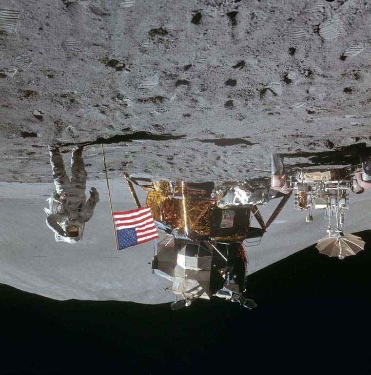
National Aeronautics and Space Administration

                                   Revision and History Page

      Status                Revision No.        Change No.   Description   Release Date
     Baseline                      13                         Baseline      07/20/2011

                                                                                          2
National Aeronautics and Space Administration

    HUMAN EXPLORATION & OPERATIONS MISSION DIRECTORATE
        STRATEGIC ANALYSIS AND INTEGRATION DIVISION
                   NASA HEADQUARTERS

           NASA’S RECOMMNEDATIONS TO SPACE-FARING ENTITIES: HOW TO
           PROTECT AND PRESERVE HISTORIC AND SCIENTIFIC VALUE OF U.S.
                           GOVERNMENT ARTIFACTS

    THIS DOCUMENT, DATED JULY 20, 2011, CONTAINS THE NASA RECOMMENDATIONS
    AND ASSOCIATED RATIONALE FOR SPACECRAFT PLANNING TO VISIT U.S.
    HERITAGE LUNAR SITES.

    IT IS REQUESTED THAT ANY ORGANIZATION HAVING COMMENTS, QUESTIONS OR
    SUGGESTIONS CONCERNING THIS DOCUMENT CONTACT ROBERT M. KELSO, NASA
    JOHNSON      SPACE    CENTER,    PHONE     713.213.3106 OR    EMAIL
    ROBERT.M.KELSO@NASA.GOV

                                                                            3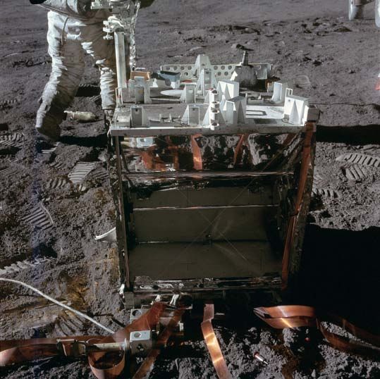
National Aeronautics and Space Administration

                                            Table of Contents
REVISION AND HISTORY PAGE                                            2
SECTION A1 – PREFACE, AUTHORITY, AND DEFINITIONS                     5
PREFACE                                                              5
DEFINITIONS                                                          7
A1-1    DISTURBANCE                                                  7
A1-2    APPROACH PATH                                                7
A1-3    DESCENT/LANDING (D/L) BOUNDARY                               7
A1-4    ARTIFACT BOUNDARY (AB)                                       8
A1-5    VISITING VEHICLE SURFACE MOBILITY BOUNDARY (VVSMB)           8
A1-6    OVERFLIGHT                                                   8
A1-7    CONTAMINATION                                                8
A1-8    REFERENCE SYSTEM                                             9
A1-9    KEEP-OUT ZONE                                                9
SECTION A2 – DESCENT AND LANDING (D/L)                              10
RECOMMENDATIONS FORMAT                                              10
TARGETING                                                           10
A2-1    APPROACH PATH                                               10
A2-2    NO OVERFLIGHT                                               11
A2-3    TOUCHDOWN TARGETING                                         11
A2-4    DISPOSAL OF BRAKING STAGE(S)                                14
A2-5    USE OF NATURAL TERRAIN BARRIERS                             14
A2-6    COLLISION AVOIDANCE WINDOWS                                 15
A2-7    LANDER ORIENTATION FOR FINAL APPROACH/LANDING RELATIVE
        TO THE U.S.HERITAGE SITE (MULTI-ENGINES DESCENT CASE)       16
SECTION A3 – MOBILITY                                               17
ROVERS/HOPPERS/KEEP-OUT ZONES                                       17
A3-1    GENERAL OVERVIEW – HISTORICAL PERSPECTIVE PER APOLLO SITE   17
A3-2    KEEP-OUT ZONE – APOLLO 11 & 17 SITES                        17
A3-3    KEEP-OUT ZONE – APOLLO 12, 14-16 SITES                      19
A3-5    KEEP-OUT ZONE – IMPACT SITES                                21
A3-6    KEEP-OUT ZONE – ROVERS AT APOLLO SITES                      22
A3-7    LINEAR WHEEL SPEED OF ROBOTIC ROVERS                        22
A3-8    BACK-TRACKING                                               23
A3-9    HOPPERS AT APOLLO SITES                                     23
A3-10   LOW-ALTITUDE FLY-BY OF APOLLO SITES                         24
SECTION A4 – CONTAMINATION                                          26
A4-1 PHYSICAL CONTACT                                               26
A4-2 DUST                                                           26
A4-3 UN-BURNED/RESIDUAL PROPELLANTS                                 26
A4-4 PLANETARY PROTECTION                                           27
A4-5 BIOLOGICAL                                                     27
APPENDIX A – ACRONYMS                                               29
APPENDIX B – NASA ENGINEERING / SAFETY CENTER (NESC) EVALUATION
OF APOLLO ARTIFACTS AS WITNESS PLATES                               30
APPENDIX C – NASA LUNAR SCIENCE ASSESSMENT OF
APOLLO SITES AS WITNESS PLATES                                      43
APPENDIX D – APOLLO MISSIONS LUNAR ASSETS                           49

                                                                         4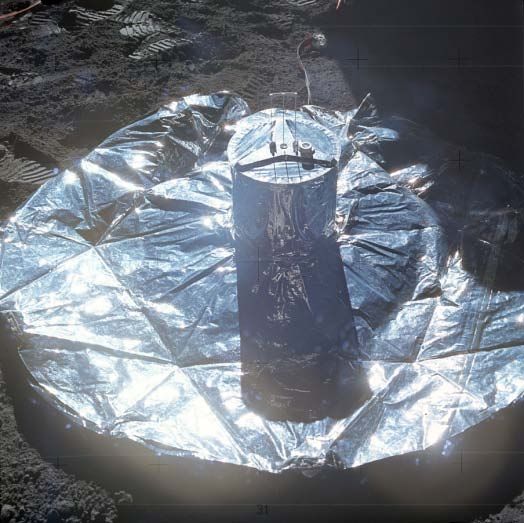
National Aeronautics and Space Administration

   SECTION A1 – PREFACE, AUTHORITY, AND DEFINITIONS

PREFACE
NASA recognizes the steadily increasing technical capabilities of space-faring commercial
entities and nations throughout the world and further recognizes that many are on the verge of
landing spacecraft on the surface of the moon. Representatives of commercial entities have
contacted NASA seeking guidance for approaching U.S. Government (USG) space assets on
the lunar surface – out of respect for hardware ownership, and a sincere desire to protect
general scientific and historic aspects of these sites. Because there is no precedent for this
situation throughout nearly 50 years of spaceflight, there are no USG guidelines or requirements
for spacecraft visiting the areas of existing USG-owned lunar hardware regardless of condition
or location.

Fortunately, there are several lunar experts across NASA and the scientific, historical, legal,
materials, and flight-planning communities who can provide some initial guidance for these lunar
endeavors. NASA has performed recent propellant/plume and lunar regolith impingement
analyses and initiated a science evaluation that examined the risks and concerns of damage to
the heritage Apollo landing sites resulting from future spacecraft descent/landing and associated
surface and low-altitude flight mobility. From a scientific perspective, many sites are still active
(e.g., Apollo retro-reflectors), and continue to produce material, biological, and physical scientific
data associated with long-term exposure of human-created systems (e.g., witness plates) to the
lunar environment. NASA has also considered impacts to non-Apollo USG lunar artifacts.

Until more formal USG guidance is developed and perhaps a multilateral approach is developed
to reflect various nations’ views on lunar hardware of scientific and historic value, NASA has
assembled this document that contains the collected technical knowledge of its personnel – with
advice from external experts and potential space-faring entities – and provides interim
recommendations for lunar vehicle design and mission planning teams. As such, this document
does not represent mandatory USG or international requirements; rather, it is offered to inform
lunar spacecraft mission planners interested in helping preserve and protect lunar historic
artifacts and potential science opportunities for future missions.

These recommendations are intended to apply to USG artifacts on the lunar surface – these
artifacts include:
             A. Apollo lunar surface landing and roving hardware;
             B. Unmanned lunar surface landing sites (e.g., Surveyor sites);
             C. Impact sites (e.g., Ranger, S-IVB, LCROSS, lunar module [LM] ascent stage);
             D. USG experiments left on the lunar surface, tools, equipment, miscellaneous EVA
                hardware; and
             E. Specific indicators of U.S. human, human-robotic lunar presence, including
                footprints, rover tracks, etc., although not all anthropogenic indicators are
                protected as identified in the recommendations.

Because of the relevance of these recommendations to current and future lunar elements
deposited by other space-faring entities, NASA has begun engaging in dialogue with foreign
space agencies, as appropriate.

                                                                                                         5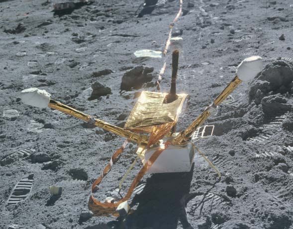
National Aeronautics and Space Administration

LEGAL FRAMEWORK

The USG continues to maintain ownership of NASA hardware and other property on the surface
of the moon, including the Apollo artifacts. These recommendations are not legal requirements;
rather they are technical recommendations for consideration by interested entities. NASA seeks
coordination in advance of lunar activities that would impact NASA artifacts of historic and
scientific interest to ensure that all appropriate interests are recognized and protected. NASA
recognizes that these recommendations may evolve and welcomes the opportunity to work with
foreign space agencies and other entities planning robotic lunar missions. As part of the USG,
NASA is committed to meetings USG responsibilities under international law.

U.S. law authorizing NASA to make these recommendations include the following:
           • National Aeronautics and Space Administration Act
           • 2010 NASA Authorization Act
           • United States Constitution --“Property Clause”
           • Federal Property and Administrative Services Act of 1949, as amended
           • General Services Administration Regulations
           • 18 U.S.C. 7

These recommendations are consistent with international law, including the following: The
1967 U.N. Outer Space Treaty (OST), which provides, in part:
          • That outer space shall be free for exploration and use by all states;
          • That there should be freedom of scientific investigation in outer space;
          • That outer space is not subject to national appropriation;
          • That parties to the treaty retain jurisdiction and control over objects launched into
             outer space that are listed on their registries, while they are in outer space and
             that ownership of objects launched into outer space is not affected by their
             presence in outer space or by their return to Earth;
          • That nations be guided by the principle of cooperation and mutual assistance in
             lunar exploration and use, with due regard to the corresponding interests of other
             parties to the treaty; and
          • That international consultations must take place prior to the commencement of
             an activity that any party has reason to believe would cause potentially harmful
             interference with activities of other parties.

    APPROACH: NASA is seeking to promote the development and implementation of
    appropriate recommendations, such as those provided herein, with interested private
    sector entities and, as appropriate, working within the USG and with foreign
    governments.

                                                                                                    6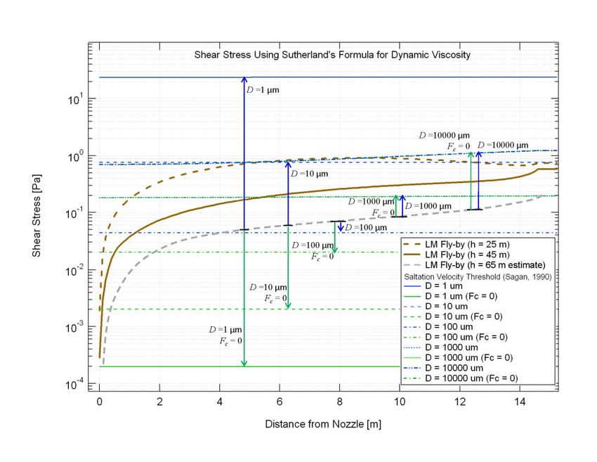
National Aeronautics and Space Administration

DEFINITIONS

A1-1 DISTURBANCE
The term “disturbance” in this context means: to effect a change or perturbation to the site
artifacts resulting in loss of historic and scientific processes and information. Some spacecraft
operations, like descent/landing or overflight, can result in significant damage to the site
artifacts; while other operations (e.g., a rover traversing an Apollo site) could result in significant
loss to the scientific value of the site.

    RATIONALE:
    Since the completion of the Apollo lunar surface missions in 1972, no missions have
    returned to visit these historic sites, leaving them in pristine condition and undisturbed
    by artificial processes (the sites have changed due to normal space weathering). It is
    anticipated that future spacecraft will have the technology and their operators will have
    the interest to visit these sites in the coming years. These visits could impose
    significant disturbance risks to these sites, thus potentially destroying irreplaceable
    historic, scientific and educational artifacts and materials.

    A site may include multiple areas of interest, depending upon the specific mission.
    For example, the Apollo 11 site can be easily included within a single boundary
    whereas the Apollo 17 site, with additional mobility provided by the lunar rover, may
    include multiple boundaries around the landing area as well as around each of the
    traverse sampling sites.

A1-2 APPROACH PATH
The ‘approach path’ is defined as the intended path of the spacecraft, plus the width of the
three-sigma dispersion for the path.

A1-3 DESCENT/LANDING (D/L) BOUNDARY
The D/L boundary is defined as the outer perimeter that establishes a keep-out radius for the
approach path of any lander/spacecraft toward any USG heritage lunar site.
    • For heritage lander sites (e.g., Apollo, Surveyor): This boundary thus defines an area
       beginning at the lunar surface site of interest and extending to a 2.0 km radial distance
       from the site where no overflight of a landed spacecraft may occur.
    • For the heritage impact sites (e.g., Ranger, S-IVB): This boundary thus defines an area
       beginning at the lunar surface site of interest and extending to a 0.5 km radial distance
       from the center of the impact site where no overflight of a landed spacecraft may occur.
This boundary prevents the plane of the descent trajectory from crossing into the keep-out
radius at any point during the descent, thus remaining tangential to the boundary. It is
incumbent on each visiting spacecraft to ensure no intrusion into this boundary during descent
and landing, including nominal and off-nominal operations.

    RATIONALE:
    The 2.0 km keep-out radius applies to the descent/approach path of the visiting
    vehicle to address three main concerns during descent:

                                                                                                          7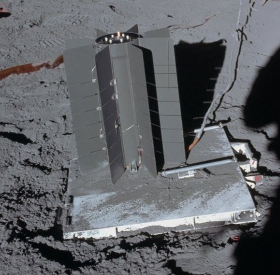
National Aeronautics and Space Administration

         1. Overflight – possibility of creating high-velocity particles during descent,
            directly impinging plume on the heritage site
         2. Near overflight – exhaust-blown dust onto the site
         3. System failure during descent – collision potential / dust creation

    The first two scenarios occur near the surface, and the ejecta flux protection of the 2.0
    km touchdown keep-out radius will prevent those.

    For the third scenario: In case of a complete loss of thrust, the instantaneous impact
    point (IIP) of the vehicle lies in the plane of the trajectory. Generally the IIP lies
    downrange of the landing target, but there are some cases in which it is up-range,
    depending on the descent trajectory. A reasonable constraint would be to require that
    the plane of the descent trajectory not cross into a similar type of keep-out radius at
    any point during the descent. This requirement would cover the overflight concerns (1
    and 2 above) as well.

    With reference to the impact sites, a 0.5 km distance is selected to allow closer D/L
    targeting than is allowed for the USG heritage lander sites (Apollo, Surveyor). The
    heritage lander sites have flight hardware that is elevated above the lunar surface,
    exposing it to high-velocity particle impacts created by the descent engines. However,
    the impacts sites sit much farther below the surface terrain and are less likely to be
    damaged by the ejecta particles resultant from the arrival of the visiting vehicle.

A1-4 ARTIFACT BOUNDARY (AB)
The AB will be established to specifically encompass all artifacts at a particular site to prohibit
interaction/visitation within that area in order to protect the artifacts of interest: descent stage,
lunar rover, flag, Apollo Lunar Surface Experiments Package (ALSEP) experiments, etc.

A1-5 VISITING VEHICLE SURFACE MOBILITY BOUNDARY (VVSMB)
The VVSMB defines the specific areas for each heritage site where surface mobility is
recommended to assess/examine the artifacts of the site without disturbing the site/artifact and
without directly contacting any of the hardware in the AB. The surface mobility boundary will be
determined to allow the maximum recommended access for scientifically assessing the artifacts
of the site while ensuring minimal disturbances. These boundary conditions will vary by site,
depending on the site’s historic value, and will contain the artifacts within the specified artifacts
boundary areas.

A1-6 OVERFLIGHT
Overflight is defined as the specific flight path of an entering spacecraft or braking stage that
results in a trajectory over the heritage site (D/L boundary).

A1-7 CONTAMINATION
Contamination is the act of depositing chemical, biological or physical material onto artifacts at
the heritage site such that the deposition reduces its historical, engineering, or scientific value.
Contamination can take on several forms, including surface particulate, non-volatile residue,
volatile hydrocarbons, and microbial.

                                                                                                        8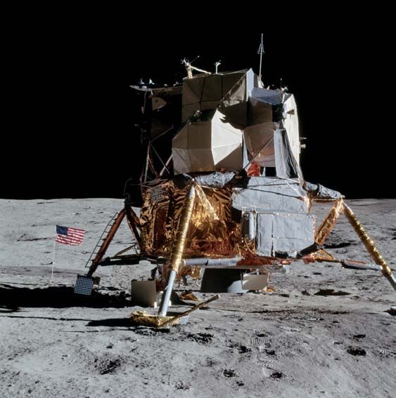
National Aeronautics and Space Administration

Analysis of returned Surveyor 3 spacecraft parts showed chemical contamination from Apollo 12
LM exhaust compounds (Reference: NASA-SP-284, 1972).

A1-8 REFERENCE SYSTEM
Each lunar spacecraft should have an onboard reference system to identify the physical location
description of the D/L, AB and VVSMB. Such a reference system will assist in ensuring that all
visiting spacecraft have knowledge of the identified boundaries.

A1-9 KEEP-OUT ZONE
A keep-out zone is the recommended boundary areas into which visiting spacecraft should not
enter. It is desirable to isolate certain locations relative to the D/L, AB and VVSMB from visiting
spacecraft. A particular zone's radius will vary as a function of the artifact and site location.

                                                                                                      9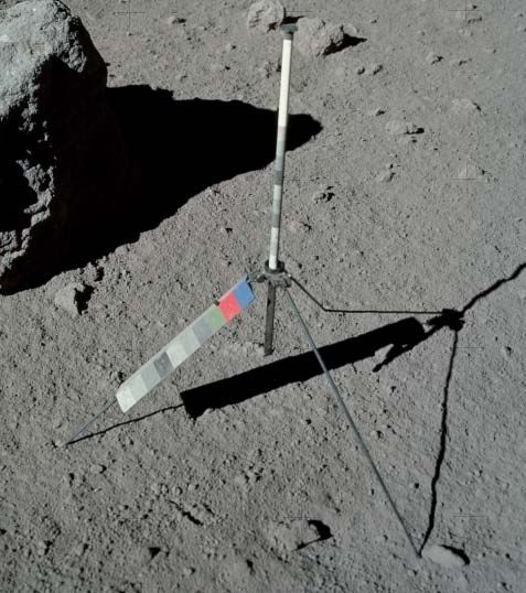
National Aeronautics and Space Administration

                SECTION A2 – DESCENT AND LANDING (D/L)

Recommendations Format
The recommendations presented in this document are provided in topical sections with indented
recommendations and rationale, as applicable. Recommendations are synopses of NASA and
subject matter expert opinions; rationales capture explanatory comments supporting the
recommendation and any associated analysis.

TARGETING
A2-1     APPROACH PATH

    RECOMMENDATION:
    The approach path for the D/L trajectory should be tangential to the D/L boundary in
    order to protect the site from off-nominal descent/landing situations.

    RATIONALE:
    The 2.0 km keep-out radius applies to the descent/approach path of the visiting
    vehicle to address three main concerns during descent:

         1. Overflight – possibility of creating high velocity particles from the descent
            where there could exist direct plume impingement on the heritage site
         2. Near overflight – exhaust-blown dust onto the site
         3. System failure during descent – collision potential / dust creation

    The first two scenarios occur near the surface, and the spirit of the 2.0 km touchdown
    keep-out radius will prevent those.

    For the third scenario: In case of a complete loss of thrust, the instantaneous impact
    point (IIP) of the vehicle lies in the plane of the trajectory. Generally the IIP lies
    downrange of the landing target, but there are some cases in which it is up-range,
    depending on the descent trajectory. A reasonable constraint would be to require that
    the plane of the descent trajectory not cross into a similar type of keep-out radius at
    any point during the descent. This requirement would cover the overflight concerns (1
    and 2 above) as well.

    By specifying a keep-out radius for the approach plane, it would still permit a large
    number of different approach paths to the site. Mission designers could then design
    the descent trajectory geometry (inclination and ascending node combination) such
    that the plane does not cross within this keep-out radius. More specifically, it would be
    the plane with appropriate error bounds drawn to cover for anticipated dispersions.

    A 0.5 km keep-out radius applies to the descent/landing path of the visiting vehicle to
    any of the USG heritage impact sites. This distance allows closer targeting (versus the
    heritage lander sites) for both lander/rover and hopper configuration landers.

                                                                                                10
National Aeronautics and Space Administration
Figure 1: Possible Approach Path Scenarios
A2-2 NO OVERFLIGHT
RECOMMENDATION:
The visiting vehicle trajectory should remain tangential to the D/L boundary to ensure
no overflight of the heritage sites as defined by the D/L boundary.
RATIONALE:
Overflights of the USG lunar artifacts could result in unwanted deposition of un-burned
propellants and possible collision with the site due to trajectory/navigation errors.
Overflight could also create a situation in which unexpected engine failure results in an
uncontrolled trajectory into (or too close to) the USG lunar artifacts.
A2-3 TOUCHDOWN TARGETING
RECOMMENDATION:
Touchdown / impact points (IP) should be targeted to a distance of no less than 2.0
km or three-sigma of the landing uncertainty (whichever is greater) from any USG
heritage landers in order to avoid intrusion into the sites during landing and to place
the landing point “over the lunar horizon”. This should include consideration for
ensuring that the maximum dispersion ellipse maintains the no-closer-than 2.0 km
distance.
11National Aeronautics and Space Administration
Figure 2: Example of 2.0 km D/L Keep-out Radius at Apollo 17 Taurus-Littrow Landing Site.
RATIONALE:
NASA analysis using gas flow codes has indicated that rocket exhaust plumes from
the landing stages can induce high injection velocities of the top layer of the lunar
surface; this analysis is further supported by the mathematical analysis performed
prior to the Apollo program before such codes were developed. The plume modeling
also predicts that the impingement from the descent engine(s) on the loose lunar
material creates a nearly flat sheet of blowing material, a broad cone of particulate
ejecta that rises at an angle between 1 and 3 degrees elevation above the local terrain
on all sides around the landing spacecraft. This predicted ejection angle of 1 to 3
degrees is confirmed by photogrammetric techniques applied to the blowing dust
clouds seen in the descent videos of the Apollo landings.
Analysis further indicates that these particles can achieve ejection velocities between
300 and 2000 meters per second (m/s) with the smaller particles generally traveling
faster. Because there is negligible ambient lunar atmosphere outside the plume, the
particles continue at that velocity until striking the lunar surface far away. Some
particles travel almost all the way around the moon before impact. The smallest, dust-
sized particles achieve near-lunar escape velocity, 2.37 km/s, and even exceed it by a
significant margin, sending them into solar orbit, according to some plume simulations.
These conclusions are corroborated by the observations of the Apollo crews. Several
12National Aeronautics and Space Administration
crew members reported that the blowing material was a flat sheet close to the surface,
so that rocks could be seen through the sheet and/or protruding through the top of it.
During Apollo 11, Buzz Aldrin reported that while this material was blowing, the lunar
horizon became “obscured by a tan haze,” which indicates that the ejected particles
were moving fast enough to travel over and beyond the horizon. For the dust-sized
particles, the highest velocity achieved is equal to the plume gas velocity, which
depends on its combustion temperature and thus chemical composition and, to a
lesser degree, the vehicle’s thrust. Thus, a smaller landing vehicle (with comparable
propellants) can eject dust-sized particles at comparable velocities, although in lower
quantities (mass) per second.
Careful review of the landing videos, and comparison to plume modeling, shows that
gravel and rocks 1 cm to 10 cm in diameter were also ejected by the plume at speeds
between 5 and 50 m/s. Ballistic calculation indicates that these rocks impacted the
lunar surface up to 1.5 km from the LM. It is the inertia of these larger particles (in
contrast to the low inertia of dust-sized particles) that prevents them from achieving
velocities comparable to the plume gas before they run out of the plume into lunar
vacuum. Thus, for a smaller lander with less thrust (lower plume gas density), the
rocks and gravel will achieve an even smaller fraction of the plume gas velocity and
will travel a shorter distance from the landing site. Vehicles larger than the LM could
eject rocks a greater distance.
Experiments have shown that lunar soil is highly abrasive and effective as a
sandblasting medium. The Apollo 12 LM landed 155 m from the Surveyor 3 spacecraft
and retrieved material samples from the spacecraft for later analysis. Even though
Surveyor was in a crater and below the horizontal plane by 4.3 m and thus “under” the
main sheet of material blown from the LM, the Surveyor spacecraft received significant
sandblasting and pitting from the Apollo landing. This suggests that collisions between
the ejected particles within the main dust sheet scattered them out of that sheet into a
much broader but lower-density spray than described above, and it was the scattered
particles that impinged on the Surveyor. Comparison with the optical density of the
blowing soil indicates that if the Surveyor had been directly impinged by the main
sheet, it would have sustained several orders of magnitude greater surface damage,
including dust implantation, scouring, pitting, cracking, and microscopic crushing of the
surface materials. Thus, the Surveyor’s damage under-represents the degree of
damage that could have occurred from an LM-sized vehicle’s plume at that distance.
Also, the damage to the Surveyor would have been greater if any of the ejected gravel
pieces or rocks had struck it (the odds of such an occurrence have not yet been
quantified).
Other cases of plume impingement effects have been documented in addition to the
Surveyor damage. These include two cases (Apollo 15 and 16) where the launch of
the Apollo LM Ascent Stage (AS) blew blankets that had been left on the surface, and
the blankets almost impacted and damaged the deployed scientific instruments.
O’Brien reported that when the AS lifted off in both Apollo 11 and Apollo 12, the solar
cells in the Dust Detector Experiments (DDE) had an immediate change in their
received sunlight – sometimes less and sometimes more – attributable to dust being
delivered to or knocked off the cells, respectively. In Apollo 11, the DDE was 17 m
away from the LM, and in Apollo 12 it was 130 m away. At the latter distance, the
plume gas would be too rarefied to have much effect, so the observed removal of dust
from the DDE was due to the impingement of high-velocity ejecta.
13National Aeronautics and Space Administration
At every distance from a spacecraft landing on the Moon, there will be ejected
particles that impact at that distance. At large distances the impingement flux
becomes small and eventually negligible. However, requiring large distances to
protect the Apollo sites could make it impractical for missions to visit them. A landing
distance that is specified as a means to protect the sites while still enabling access
must be a compromise that reduces the impingement effects without entirely
eliminating them. The lunar horizon is roughly 1.8 km from any given point on the
lunar surface. By targeting the landing point at 2.0 km from the closest lunar artifact,
the main sheet of high-velocity dust-sized particles – which constitutes the largest
fraction of the lunar soil – will fly over the top of the artifact site and thus minimize
direct impingement. Larger rock or gravel-sized ejecta, which will travel at lower
velocities, will impact the lunar surface well short of the horizon, thus also missing the
artifact site. The intermediate range of particle sizes (larger, sand-sized particles),
which will travel over the horizon but with sufficient downward curvature to strike the
artifact site, are a minority fraction of the lunar soil and will have a much lower flux
density at impingement from that distance than if the spacecraft were landing closer,
thus reducing damage.
A2-4 DISPOSAL OF BRAKING STAGE(s)
RECOMMENDATION:
The disposal of all deorbit braking stages should be targeted tangential to the D/L
boundary to ensure no overflight of a heritage site and to ensure that the IP is greater
than 2.0 km from the heritage site (0.5 km for impact sites).
RATIONALE:
Minimize collision potential and the creation of dust clouds within the historic and
scientific sites.
A2-5 USE OF NATURAL TERRAIN BARRIERS
RECOMMENDATION:
If possible, natural lunar terrain barriers such as hills, crater rims, ridges, or terrain
slopes should be used to block the spray of the landing spacecraft. Note that use of
natural terrain barriers does not change the D/L boundary recommendations.
RATIONALE:
The recommended 2.0 km landing distance reduces but does not entirely eliminate
impingement of high-velocity particles. Degradation of the lunar artifacts by ejecta
impingement is a cumulative and irreversible effect. It is expected that with increasing
access to the lunar surface these sites may be visited frequently, which over time will
significantly multiply the effect. Therefore, it is desirable to further reduce impingement
to as low as reasonably achievable (ALARA) by taking advantage of natural barriers to
block the spray. Changes in terrain slope can “ramp” the ejecta into a higher ejection
angle so that a larger fraction will fly over the top of the protected site. Natural barriers
14National Aeronautics and Space Administration
can block the direct flux of larger particles that curve downward as they cross the
horizon, preventing them from reaching the site. It should be noted that the barriers
will absorb the momentum of larger impinging particles, but in lunar vacuum, barriers
will simply scatter the dust-sized particles without significantly reducing their velocity.
It may be possible that using a barrier to scatter the main dust sheet could result in
more dust-sized material raining down onto the protected site than if the 2.0 km
distance were the only method of mitigation. Dust-sized particles that scatter and then
rain down on the site will impinge with no significant reduction in velocity. Further
analysis could determine in particular cases of various terrain features whether they
reduce or increase the dust impingement at the site, and if they increase the
impingement, it could be determined whether that increase is outweighed by the
barrier’s blockage and absorption of the larger-sized particles that would have
otherwise curved over the horizon and hit the protected site.
A2-6 COLLISION AVOIDANCE WINDOWS
RECOMMENDATION:
An analysis specific to the landing vehicle should be performed prior to selecting the
landing time and location, in order to determine whether its ejected soil and dust will
reach altitudes where it may damage lunar orbiting spacecraft; if so, collision
avoidance (COLA) windows should be implemented to prevent landing with the
precise timing that could damage those spacecraft.
RATIONALE:
From a hypervelocity impact perspective, there may be a concern for damage to
sensitive satellite surfaces such as optics (e.g., camera lenses, star trackers,
windows, solar cells), and thin materials that should not be perforated in order to
function (e.g., light-tight enclosures, thermal insulation). The level of concern would
depend on the specific hardware component function, impact sensitivity, and failure
criteria.
Analysis shows that, depending on the specifics of the lander’s propulsion system,
ejected dust may exceed altitudes typical of lunar orbiting spacecraft, and perhaps
even exceed lunar escape velocity. Analysis further shows that the density of this
ejecta, when it reaches orbital altitudes, is still sufficient to cause numerous impacts
on a passing spacecraft. These impacts will be in the hypervelocity regime due to the
high relative velocity of the ejecta and the spacecraft. The effects of such impacts are
unknown at this time, but might cause significant harm to sensitive features of the
spacecraft such as scientific optical instruments. Therefore, to avoid causing damage,
an analysis using the particular propulsion system characteristics should be performed
to determine the ejecta velocity and the time it will take the ejecta to reach and then
pass through the orbital trajectories of each spacecraft in lunar orbit at that time. The
particular times that those spacecraft also pass through those intersection points,
minus the travel time of the ejecta to get there, determines the landing times that
should be avoided. The COLAs will be defined as the windows of time with adequate
margin (typically only a few minutes) to avoid landing at that particular location on the
moon on that date. NASA has developed software tools to perform this analysis.
15National Aeronautics and Space Administration
A2-7 LANDER ORIENTATION FOR FINAL APPROACH/LANDING RELATIVE TO THE
U.S.HERITAGE SITE (multi-engines descent case)
RECOMMENDATION:
Given a multi-engine lander, a reference system is defined to place an axis through
engines 1 and 3 and another axis through engines 2 and 4. The lander should be
placed in an orientation for final approach/landing such that either of the two-engine
axes is directly aligned with the USG lunar heritage site (green arrows in Figure 3).
Thus, during low-altitude trajectories, the plume reflection planes would be pointed
away from the lunar heritage site.
Figure 3: Diagram of multiple engine spacecraft ejecta paths – orange (solid) arrow
denotes direction of maximum ejecta flux ‘rooster tail’ along plume reflection planes.
Open (green) arrow identifies direction of minimum ejecta flux.
RATIONALE:
Recent analysis has indicated that the multi-engine lander case creates an
exaggerated effect on the lunar soil. The plume interaction between the multiple
descent engines creates a “rooster-tail” of blown particles unlike the single engine
case. This rooster tail thus produces particle trajectories in multiple angle trajectories
rather than the particle sheet of 1 to 3 degrees from the local horizontal as seen in the
single engine case.
Numerical simulations show that soil erosion is ejected at a much higher flux, much
higher angles above horizontal, and at much higher velocities along these planes than
compared to the ejection of particles form a single engine lander. The particles
ejected along these planes travel much longer distances and would strike the Apollo
sites with higher impingement flux and higher impact velocities, causing much greater
damage than would occur in the single-engine case. Further analysis is required to
quantify this effect, but the safe landing distance limit and safe flyby altitude limit are
based on the single-engine case, and therefore the flux along the plume reflection
planes will significantly exceed the intent of those limits. Keeping the vehicle oriented
so that Apollo site is always midway between its plume reflection planes will ensure
the least amount of damage to the site.
16National Aeronautics and Space Administration
SECTION A3 – MOBILITY
ROVERS/HOPPERS/KEEP-OUT ZONES
MOBILITY
A3-1 GENERAL OVERVIEW – HISTORICAL PERSPECTIVE PER APOLLO SITE
RECOMMENDATION:
While all the Apollo sites represent significant historical/heritage value in material
culture, the Apollo 11 and 17 landing sites carry special historical and cultural
significance. It is recommended that the sites for Apollo 11 and 17 be treated as
unique by prohibiting visits to any part of the site and that all visiting vehicles remain
beyond the artifact boundaries (AB) of the entire site.
RATIONALE:
Apollo 11 was a pivotal event in human exploration and technology history. Apollo 11
marked the first human flight to the lunar surface; Apollo 17 represented the last within
the Apollo Program. Project Apollo in general, and the flight of Apollo 11 in particular,
should be viewed as a watershed in human history and humanity. It was the first
instance in human history in which emissaries from this planet visited another body in
the solar system. It represented the culmination of years of effort, the significant
expenditure of life and resources, and the opening of a new age in human history. The
site of that first landing requires preservation; only one misstep could forever damage
this priceless human treasure.
A3-2 KEEP-OUT ZONE – APOLLO 11 & 17 SITES
RECOMMENDATION:
It is recommended that the Apollo 11 and 17 sites be protected by ABs, and thus
restricted from close inspection by visiting robotic systems. The visiting vehicle
mobility exclusion boundary will encompass all artifacts (hardware, footprints, etc.) for
these sites.
A. For the Apollo 11 site, the keep-out zone extends 75 m from the lunar module
descent stage to encompass all hardware and human activity (Figure 4).
B. For the Apollo 17 site, the keep-out zone extends 225 meters from the lunar
module descent stage (Figure 5).
RATIONALE:
It is desired to maintain the integrity of the Apollo 11 and Apollo 17 sites. Since the
Apollo 11 site is of great historic significance and yet is fairly contained for the
hardware and footprints, landers may touch down over the horizon to protect the site
from damage, and mobility systems can approach the site as long as they remain
outside the larger mobility exclusion zone. The 75 m radius for Apollo 11 ensures that
all human activities for that flight are contained within the keep-out zone.
17National Aeronautics and Space Administration
It is desirable to also isolate an Apollo J-mission site. Since Apollo 11 was the first site
and Apollo 17 the last site, this recommendation preserves and protects each site for
future scientific investigations.
Also note that the Apollo 11 ALSEP retro-reflector continues to be an active scientific
experiment and can be easily degraded by particulate and chemical contamination.
APOLLO 11
Figure 4: Apollo 11 AB extends 75 m from the LM descent stage.
18National Aeronautics and Space Administration
APOLLO 17
Figure 5: Apollo 17 AB extends 225 m from the LM descent stage.
A3-3 KEEP-OUT ZONE – APOLLO 12, 14-16 SITES
RECOMMENDATION:
A. More access should be provided to individual components/artifacts at the Apollo 12,
14-16 sites in order to allow for enhanced scientific and exploration-based
assessments. The following keep-out zones have been identified by component/type:
• Descent stage – 3 meters buffer distance
• Lunar rover (LRV) – 1 meter buffer distance
• ALSEP experiments – 1 meter buffer distance
• Sampling sites – 1 meter buffer distance
• All other artifacts (flag, tools, storage bags, etc.) – 1 meter buffer distance
• No restrictions on footprints/LRV tracks outside the indentified keep-out zones.
RATIONALE:
The Apollo lunar artifacts are still considered ongoing experiments in space
weathering. The identified keep-out zones allow for close inspection of the artifacts
while still preserving their scientific integrity. Also note that the Apollo ALSEP retro-
reflectors continue to be active scientific experiments and can be easily degraded by
particulate and chemical contamination.
19National Aeronautics and Space Administration
RECOMMENDATION:
B. The laser ranging retro-reflectors (LRRRs) should be carefully preserved (See
Section A2). LRRR experiments are found at the Apollo 11, 14, and 15 sites (as
well as the Soviet Lunokhod 1 and 2 rover sites). The LRRRs should be treated as
special cases with approach mobility being tangential to the site. Once within a 10
m radius zone of the LRRR, mobility can only proceed at speeds that do not propel
regolith particles in front of the rover (see Section A3-7) up to the total exclusion
zone of 1 m radius around the retroreflector. Direct approach to the LRRR is not
recommended.
RATIONALE:
While all landing/artificial impact sites have historical value, it should be recognized
that the Apollo-era lunar Laser Retro-Reflector Ranging (LRRR) experiment is still
ongoing, with laser ranging to passive retroreflectors placed on the lunar surface.
The lunar LRRR experiment measures the distance between the Earth and the moon
using laser ranging. Since these are active experimental stations, NASA prefers to not
risk compromising or contaminating these activities through robotic visits. It should be
noted that a physical disturbance would affect 40 years of LRRR data continuity. The
stability of the reflectors is critical to a variety of geophysical and relativistic physics
problems. It is essential that these sites not be disturbed, however, careful
observations of their current state would allow scientists a better idea of what is
causing the degradation in the laser return signal, but also help in designing the next
generation of LRRRs.
Five lunar sites contain LRRRs: Apollo 11, 14, and 15; and two Soviet Lunokhod
Rovers deployed by Luna 17 and 21. Accidental deposition of dust on the surfaces of
these LRRRs or sandblasting of the retroreflector surfaces would seriously diminish
the science return because, as noted by Williams and Dickey (2003)1, many of the
science parameters derived from laser-ranging data are very sensitive to time span
(i.e., the longer time that data are gathered, the better the science return). However,
science can be enabled by close-range (National Aeronautics and Space Administration
A3-4 KEEP-OUT ZONE – SURVEYOR SITE
RECOMMENDATION:
A 1 m buffer keep-out zone should be in effect around all Surveyor spacecraft
hardware.
A3-5 KEEP-OUT ZONE – IMPACT SITES
RECOMMENDATION:
While rovers may drive to the rim of the impact crater and observe, it is recommended
entry into the impact crater not occur without prior NASA coordination.
RATIONALE:
It is common practice for the Mars Exploration Rovers (MER) Spirit and Opportunity to
rove up to a crater rim, and track around the rim prior to entering a given crater. For
the Ranger and S-IVB impact craters, an important scientific objective is to examine in
the crater and observe the morphology (because they look different from natural
impact craters) and to map out the distribution of debris.
Ranger 9
Figure 6: The Ranger 9 impact site. Note: red circle only denotes the location of the
Ranger impact site, rather than designating a keep-out zone)
21National Aeronautics and Space Administration
A3-6 KEEP-OUT ZONE – ROVERS AT APOLLO SITES
RECOMMENDATION:
A. With the exception of the Apollo 11 and 17 sites, rovers should observe the
keep-out zones of individual artifacts at the Apollo 12, 14, 15 and 16 sites.
RATIONALE:
In general, slow-moving rovers will not create dust/deposits in and around the site
(see section A3-7 below).
RECOMMENDATION:
B. For rovers that enter the AB for Apollo site visits, the rover should be removed
from the site boundary prior to lunar sunset and end-of-mission (EOM); and not
be left within the site boundary.
RATIONALE:
NASA prefers that rovers do not remain parked within the AB at end-of-life. The
effects of a severe lunar environment on unattended/uncontrolled space and surface
vehicles could lead to containment failures, energetic events or other potential
uncontrolled events (e.g., battery venting) that could later contaminate the site.
RECOMMENDATION:
C. Tangential approach – rather than allowing a direct-approach to any given
artifact, it is recommended that aim points be selected that are tangential to the
artifact.
RATIONALE:
As recommended in Section A2-1 that all trajectory D/L paths be tangential to the
landing sites, it is suggested that a similar philosophy be used in the approach to any
heritage artifact. Currently, rovers can take pathways that could aim directly at the
artifacts, then stop within the prescribed buffer distance. But this approach doesn’t
necessarily protect for “delay-to-stop” cases or failure modes in which the stop
command is not properly received or executed. By selecting aim points that are
tangential to each artifact, rovers can still gain close access to the target, but minimize
contact in the event of “fail-to-stop” cases.
A3-7 LINEAR WHEEL SPEED OF ROBOTIC ROVERS
RECOMMENDATION:
No part of the approaching (roving) vehicle should be capable of propelling particles
more than half way to an artifact. This sets a limit on speeds of all components of a
rover in the neighborhood of artifacts. Specifically, the linear (exterior) wheel speeds
of robotic rovers should not exceed the meters/second listed below while traversing
within the site in order to avoid casting/throwing dust and particles. Rover designs
should consider containment/deflection of casting particles.
22National Aeronautics and Space Administration
Table 1: Rover wheel speed versus debris cast distance.
Distance dust can be
Velocity (m/s)
thrown (m)
3 2
5 2.8
10 4
15 5
30 7
75 11
80 11.4
200 18
RATIONALE:
Excessive speed around the AB could result in dust contamination on the heritage
flight hardware within the site.
A3-8 BACK-TRACKING
RECOMMENDATION:
The approach path prior to reaching an AB, D/L, or VVSMB is not restricted, but once
the boundary is crossed, the traverse should be the most direct approach to the
desired site location. However, once the visit is completed, the exit path(s) should be
back along the same path used for the site approach, as much as possible.
RATIONALE:
Entering and exiting along the same location is highly recommended to minimize
disturbance and contamination of site. This should apply to the first visit to that site
and all subsequent visits so the same entry and exit "paths" would be used as much
as possible.
A3-9 HOPPERS AT APOLLO SITES
RECOMMENDATION:
Landers of the hopper configuration (as with lander/rover configurations) should not
land within the 2.0 km radius defining the D/L boundary of a USG heritage lander site.
While hoppers can launch/land outside the D/L boundary, they can also perform site
inspections via an altitude-flyby per section A3-10 (see below).
23National Aeronautics and Space Administration
RATIONALE:
Some landers employ a “hopper configuration” for their mobility – reusing descent
engines to achieve flight and translation across the lunar terrain. The engines of the
hopping configuration create an upwelling of fresh regolith as it ascends from its
current location and lands in new regions, which in turn produces additional amounts
of dust and debris within the area. Despite the lack of a large, central crater beneath
the LMs in the Apollo landings, the amount of ejected soil has been calculated by
several methods (optical density, damage to Surveyor, experiments, theory, and
shape of the surface beneath the LM) and has been found to be on the order of 1 mt
(metric ton) or more. The amount of soil disturbed by a smaller lander is expected to
be less, scaling approximately with vehicle thrust, but this can still be a significant
quantity for any lunar lander. This dust and resultant high-velocity particles could
impart significant damage to a protected site, and damage the site’s historical record
(e.g. crew’s footprints and tracks in the case of Apollo landings). Propellant exhaust
and ejecta could also affect loose materials like the Modularized Equipment Stowage
Assembly (MESA) blanket or other blankets on the Descent Stage and lunar surface.
A3-10 LOW-ALTITUDE FLY-BY OF APOLLO SITES
RECOMMENDATION:
It is recommended, for hopper configuration landers, to perform “low-altitude”/
tangential fly-bys of the lunar heritage sites by translating outside of the Apollo
hardware's AB, using a minimum of 40 m altitude to the local surface and a tangential
distance from the outer hardware AB perimeter consistent with section A4-3
(unburned or residual propellant, see below).
RATIONALE:
The low-altitude, tangential fly-by approach allows hopper-configuration landers to
provide imagery of lunar heritage sites with minimal risk to the site.
Plume impingement: the top layer of the lunar surface is primarily loose particles and
dust. During lander translations over the surface, rocket engine exhaust will induce
radial ejection of the surface material at high velocities and create dust clouds. These
dust/particle streams can result in both contamination and degradation of the
protected site.
Altitudes of great than 40 m for translations should ensure negligible plume
interactions at the surface.
In the Apollo landings, the crews reported the incipient erosion altitude (the altitude at
which dust blowing first occurred during descent) based on naked-eye observations
and varied between missions. It was usually between 20 m and 50 m. On Apollo 12 it
was reported as 100 m. This was a statistical outlier, but is consistent with modeling.
It may be that the dust movement was more easily seen at lower quantities on that
mission due to the much lower sun angle. The modeling is difficult because little is
known about lunar soil’s cohesion. Best estimates so far indicate that “fine sand”
particles (around 100 µm) are more easily blown than other particle sizes, and that
their motion begins when the LM descends to near 85 m as shown in Figure 7. At that
altitude, although the fine-sand sized particles do begin to move, they do not
24National Aeronautics and Space Administration
experience sufficient lift and will not travel any appreciable distance before falling back
to the surface. Also, these particles do not have enough optical density to be seen
moving. Only clouds of particles smaller than about 10 µm should be visible to the
crew from any appreciable height. The saltating motion of those fine-sand sized
particles, however, mechanically disturbs the dust particles (National Aeronautics and Space Administration
SECTION A4 – CONTAMINATION
A4-1 PHYSICAL CONTACT
RECOMMENDATION:
Visiting spacecraft should not physically contact any USG lunar hardware. Exceptions
should be pre-coordinated with NASA.
RATIONALE:
Lunar dust and potential biological contamination may be transferred from the visiting
spacecraft onto the historical assets, degrading the historical site and/or impacting the
science value of the site. However, physical contact with USG hardware and/or impact
debris may provide additional scientific value, which should be balanced with the
potential for damage. Coordination with NASA is recommended to ensure acceptance
and understanding of all risks and benefits.
A4-2 DUST
RECOMMENDATION:
Visiting spacecraft should always adhere to the altitude and tangential distance
constraints given in section A3-10 “Low-altitude Fly-by of Apollo Sites”
RATIONALE:
Spacecraft rocket plumes are known to disturb soil on the lunar surface and create
sheets/clouds of flying dust. The distances cited in section A3-10 will protect the
Apollo site from both dust contamination and degradation from dust abrasion. All
mission phases, including low-altitude fly-by, should adhere to the recommended
distances.
A4-3 UN-BURNED/RESIDUAL PROPELLANTS
RECOMMENDATION:
When within 200 m of the lunar surface, visiting spacecraft should maintain a main
engine orientation such that a cone with a half angle of 45 degrees that is centered on
the engine axis does not intersect any portion of the keep-out zones defined in
Sections A3-2 through A3-6.
RATIONALE:
The purpose of this recommendation is to keep the lunar heritage sites from being
contaminated with propellant residue that is potentially toxic to humans and/or
damaging to Apollo hardware (e.g., corrosive). Studies have shown that droplets large
enough to be of consequence (larger than one micron in diameter) of
unburned/residual propellant from spacecraft rocket motors are confined to within 45
degrees of the engine thrust axis when the rocket is operated in a vacuum
environment. Therefore, adherence to this constraint will ensure that adverse effects
from the deposition of propellant droplets upon the Apollo artifacts will not occur.
26National Aeronautics and Space Administration
Figure 8: Illustration of plume droplet cone.
A4-4 PLANETARY PROTECTION
RECOMMENDATION:
To address planetary protection concerns, mission documentation should be prepared
consistent with the Committee on Space Research (COSPAR) Planetary Protection
Category II Guidelines, and, when available, under the guidelines of the lunar
mission’s nation’s appropriate authority. The COSPAR Guidelines involve
documentation including an inventory of organic compounds carried on or produced
by the spacecraft (e.g., trace organics released in thruster exhaust).
RATIONALE
COSPAR Planetary Protection Policy specifies that robotic missions to the moon be
designated as Planetary Protection Category II. As such, Category II missions require
documentation to be provided to the Planetary Protection Officer or other appropriate
authority of the lunar mission’s national scientific organization that participates in
COSPAR, or the COSPAR Planetary Protection Panel, which provide guidelines and
policies for implementation. For missions in which NASA participates, Category II
missions to the moon require documentation to be provided to the NASA Planetary
Protection Officer based on COSPAR policy and requirements outlined in NASA NPR
8020.12 and NASA NPD 8020.7.
A4-5 BIOLOGICAL
RECOMMENDATION:
To address concerns about microbial and biological contamination at historic and
scientific sites, visiting spacecraft should follow all recommended keep-out zones,
boundaries and restrictions outlined in these recommendations.
27National Aeronautics and Space Administration
RATIONALE
Remnant detectable microbial levels and biological contamination, if any, at historical
lunar mission sites represent valuable, irreplaceable data of scientific interest.
Concerns about microbial and biological contamination at historical sites will be
sufficiently addressed by following all recommended keep-out zones, boundaries and
restrictions outlined in these recommendations.
28National Aeronautics and Space Administration
APPENDIX A – ACRONYMS
Acronym Meaning
AB Artifacts Boundary
ALARA As low as reasonably achievable
ALSEP Apollo Lunar Surface Experiments Package
AS Ascent Stage
COLA Collision avoidance
COSPAR Committee on Space Research
D/L Descent/Landing
DDE Dust Detector Experiments
EOM End of Mission
IIP Instantaneous Impact Point
IP Impact Point
km/s Kilometers per second
LCROSS Lunar Crater Observation and Sensing Satellite
LM Lunar Module
LRRR Laser ranging retro-reflector
LRV Lunar Roving Vehicle
MER Mars Exploration Rover
m/s Meters per second
mt metric ton
OST Outer Space Treaty
PI Principal Investigator
USG U.S. Government
VVSMB Visiting Vehicle Mobility Boundary
29National Aeronautics and Space Administration
APPENDIX B – NASA Engineering / Safety Center (NESC)
Evaluation of Apollo Artifacts as Witness Plates
Future visits to the Moon’s surface, such as those anticipated by participants in the Google Lunar X-
Prize (GLXP) competition, offer a unique opportunity to study the effects of exposure to the lunar
environment on materials and articles left behind by previous lunar missions. Very little data exist
that describe what effect temperature extremes, lunar dust, micrometeoroids, solar radiation, etc.
have on man-made material, and no data exist for time frames approaching the 4 decades elapsed
since the Apollo missions. Some of the hardware on the Moon was designed to remain operable
and transmit telemetered scientific data back to the Earth, but much of what is there was meant to
be used during the Apollo mission time frame and then abandoned with no expectation of further
survivability. How these artifacts and their constituent materials have survived and been altered
while on the lunar surface is of great interest to engineers and scientists. The Apollo artifacts are,
in essence, witness plates to 38+ years on the Moon.
The NASA Engineering and Safety Center (NESC) was asked to consider these possible effects of
the lunar environment on man-made artifacts and suggest which artifacts would be the most
enticing targets for imaging or investigation by future visiting vehicles. The NESC team used Apollo
15 as a representative landing site. The Apollo 15 crew left 189 individually cataloged items on the
lunar surface, including the descent stage of the Lunar Module, the Lunar Roving Vehicle (LRV),
the Apollo Lunar Surface Experiments Package (ALSEP), and a wide variety of miscellaneous
items that were offloaded by the astronauts to save weight prior to departure. The locations of
many of these items are well documented, and numerous photographs are available to establish
their appearance and condition at the time they were left behind.
The NESC team formed for this activity consisted of several NASA Technical Fellows and members
of technical discipline teams (TDT) with expertise in thermal control, materials, mechanical systems,
lunar environment, nondestructive evaluation, and environmental control and life support (see Table
B1).
Table B1: NESC Team Members
Neil Dennehy Guidance, Navigation and Control Technical Fellow
Jared Dervan NESC Resident Engineer
Michael Dube Mechanical Systems TDT
William Prosser Nondestructive Evaluation Technical Fellow
Steven Rickman Passive Thermal Technical Fellow
Henry Rotter Life Support and Active Thermal Technical Fellow (Apollo Veteran)
Donald Shockey Materials TDT
Michael Sims Robotics TDT/Center for Collaboration Science and Applications
Michael Squire NESC Principal Engineers Office
Input was also received from members of the original Bendix Corporation team that designed
and built the ALSEP instruments. Specific thanks go to Mr. Lynn Lewis, who provided much of
the information in Table B2 and additional observations in this appendix.
30National Aeronautics and Space Administration
The task for the NESC team was to determine which artifacts were accessible and evaluate
what benefits might be realized by taking high definition images of each one. Accordingly, the
ground rules set for this NESC activity were to assume that the only scientific equipment
available will be high definition cameras, and no physical contact with the artifacts is allowed.
The NESC team’s conclusions are presented in Table B2 where they are categorized as
follows:
Materials: One of the primary objectives in looking at the artifacts is to gauge the effect
of the lunar environment on different materials. Conditions on the lunar surface vary in
temperature from +250° F to -300° F and include exposure to ultraviolet and other forms
of radiation, so material surfaces after 40 years of exposure to this environment could be
discolored, faded, dulled, flaked, rumpled, pitted, mud-cracked, scratched, and/or
covered with dust.
Structural/mechanical: The temperature extremes may have caused some artifacts to
exhibit thermal effects, and the 500-plus day-night thermal cycles may have caused
thermal fatigue damage or deformation due to dissimilar metals being in contact with
each other. In addition, micrometeoroid impacts may have produced craters whose
number, size, and appearance may be useful in updating current models. Radially
symmetric objects with several impacts may be able to give some rough directional
information as well.
Thermal: Most of the Apollo hardware received some form of thermal protection. This
included multilayer insulation (MLI), radiators/reflectors, and/or thermal paint. There is
interest is seeing how these different systems may have degraded.
Dust: Much has been documented on the characteristics of lunar dust and the
deleterious effect it has on equipment. There is also interest in dust transportation and
deposition from human activities and natural processes. Flat surfaces (especially
horizontal) and artifacts that appear pristine in Apollo photographs would be optimum
targets to look for dust deposition.
Blast Effects: Observations of how blast effects from nearby rocket engines vary as a
function of distance may be possible by looking at some affected artifacts.
Miscellaneous: Captured here are observations not easily grouped in any of the above
categories.
31You can also read