Tempo and Encore Avem Dynamics presents - RESPONSE TO THE 2015-2016 AIAA UNDERGRADUATE TEAM AIRCRAFT DESIGN COMPETITION
←
→
Page content transcription
If your browser does not render page correctly, please read the page content below
Avem Dynamics presents

 Tempo
 Encore

 Tempo and Encore
 RESPONSE TO THE 2015-2016 AIAA
UNDERGRADUATE TEAM AIRCRAFT DESIGN COMPETITION

 CALIFORNIA POLYTECHNIC STATE UNIVERSITY, SAN LUIS OBISPO

 AEROSPACE ENGINEERING DEPARTMENT

 AIRCRAFT DESIGN 2015-2016

Executive Summary
 Avem Dynamics is proud to present Tempo and Encore, the newest innovation in Light Sport Aircraft

(LSA), a family of aerobatic aircraft in response to the 2016 Request for Proposal 1 from the American Institute of

Aeronautics and Astronautics (AIAA) for the Undergraduate Team Aircraft Design Competition. As the LSA

market continues to grow, the demand for high performing, aerobatic aircraft will skyrocket, creating the perfect

market for a new company to enter. Avem Dynamics has designed a family of aerobatic aircraft that will be the

newest sensation in LSA.

 Aerobatic performance is of the utmost importance to Avem Dynamics. Tempo provides the aerobatic

performance that LSA pilots desire with a sleek, modern design that will catch the eye. With superior aerodynamic

performance, an easily maintainable structure, and lowered manufacturing costs, Tempo is accessible to all different

types of pilots. Encore is a two-seat trainer variant of Tempo, maintaining the same high performance aerodynamics

as Tempo, while allowing for superior training capabilities. Due to the high level of commonality and similar

handling qualities between Tempo and Encore, pilots will be able to use Encore as a trainer version of Tempo.

 Avem Dynamics is confident that this family of aerobatic aircraft will be profitable and desirable in the

growing LSA market.

 American Institute of Aeronautics and Astronautics
 i
Avem Dynamics Team

 Brandon Baldovin Conner Brown Dana Clarke
 Aerodynamics Performance Aerodynamics
 AIAA: 513616 AIAA: 688244 AIAA: 688327

 Matthew Teare
 James Walker Alex Ziebart
 Propulsion
 Mass Properties Configuration
 AIAA: 688324
 AIAA: 688414 AIAA: 688325

 Robert McDonald
 Aaron Drake Faculty Advisor
Faculty Advisor AIAA: 171269
 AIAA: 99736

 Kelsey Belmont Dan Baifus
 Co-Lead, Controls Co-Lead, Configuration
 AIAA: 492250 AIAA: 688228
 American Institute of Aeronautics and Astronautics
 ii
Table of Contents
1 Introduction ......................................................................................................................................................... 10
 1.1 Requirements ............................................................................................................................................. 10
 1.1.1 RFP Requirements ................................................................................................................................. 10
 1.1.2 Derived Requirements ........................................................................................................................... 12
 1.2 Design Objectives ...................................................................................................................................... 12
2 Market Analysis .................................................................................................................................................. 13
3 Aerobatic Competition ........................................................................................................................................ 16
 3.1 IAC Intermediate Category ........................................................................................................................ 17
 3.2 Aerobatic Mission Profile .......................................................................................................................... 18
4 Aircraft Sizing..................................................................................................................................................... 19
 4.1 Constraint Diagram .................................................................................................................................... 19
 4.2 Derived Maximum Lift Coefficient ........................................................................................................... 23
5 Configuration ...................................................................................................................................................... 24
 5.1 Aesthetics ................................................................................................................................................... 24
 5.2 Seating Configuration ................................................................................................................................ 25
 5.3 Landing Gear.............................................................................................................................................. 26
 5.3.1 Landing Gear Type ................................................................................................................................ 26
 5.3.2 Landing Gear Placement ........................................................................................................................ 27
 5.4 Inboard Profile ........................................................................................................................................... 28
6 Aerodynamics ..................................................................................................................................................... 30
 6.1 Airfoil Selection ......................................................................................................................................... 31
 6.2 Wing Design .............................................................................................................................................. 32
 6.2.1 Wing Span ............................................................................................................................................. 33
 6.2.2 Wing Taper ............................................................................................................................................ 35
 6.3 Drag Estimation ......................................................................................................................................... 38
 6.3.1 Drag Buildup Comparison ..................................................................................................................... 39
 6.3.2 Drag Polar .............................................................................................................................................. 40
7 Propulsion ........................................................................................................................................................... 40
 7.1 Methodology .............................................................................................................................................. 40
 7.1.1 Fixed Pitch Propellers ............................................................................................................................ 41
 7.2 Engine Trade Methodology ........................................................................................................................ 41
 7.3 Engine Selection ........................................................................................................................................ 41
 7.4 Propeller Matching ..................................................................................................................................... 42
 7.4.1 Propeller Characteristics ........................................................................................................................ 42
 7.4.2 Propeller Design Process ....................................................................................................................... 42
 7.4.3 Propeller Performance ........................................................................................................................... 43
8 Structures ............................................................................................................................................................ 47
 8.1 V-n Diagram .............................................................................................................................................. 47
 American Institute of Aeronautics and Astronautics
 iii
8.2 Spar Sizing ................................................................................................................................................. 49
 8.3 Materials and Manufacturing ..................................................................................................................... 50
 8.3.1 Material Selection .................................................................................................................................. 50
 8.3.2 Manufacturing........................................................................................................................................ 51
9 Mass Properties ................................................................................................................................................... 52
 9.1 Methodology .............................................................................................................................................. 52
 9.1.1 Wing ...................................................................................................................................................... 53
 9.1.2 Empennage ............................................................................................................................................ 54
 9.1.3 Fuselage ................................................................................................................................................. 55
 9.1.4 Systems .................................................................................................................................................. 57
 9.1.5 Furnishing .............................................................................................................................................. 57
 9.1.6 Landing Gear ......................................................................................................................................... 57
 9.2 Weight Summary ....................................................................................................................................... 57
 9.3 Commonality .............................................................................................................................................. 57
10 Stability and Controls ......................................................................................................................................... 59
 10.1 Center of Gravity ....................................................................................................................................... 59
 10.2 Longitudinal Stability................................................................................................................................. 61
 10.3 Trim Analysis ............................................................................................................................................. 62
 10.3.1 Elevator Sizing .................................................................................................................................. 65
 10.4 Directional Stability ................................................................................................................................... 65
 10.4.1 Vertical tail sizing ............................................................................................................................. 65
 10.4.1 Rudder Sizing .................................................................................................................................... 66
 10.4.2 Spin Recovery ................................................................................................................................... 67
 10.5 Aileron Sizing ............................................................................................................................................ 70
 10.6 Empennage Summary ................................................................................................................................ 71
11 Performance ........................................................................................................................................................ 72
 11.1 Flight Envelope .......................................................................................................................................... 73
 11.2 Takeoff And Landing ................................................................................................................................. 74
 11.2.1 Takeoff .............................................................................................................................................. 74
 11.2.2 Landing.............................................................................................................................................. 76
 11.3 Maximum Rate of Climb ........................................................................................................................... 77
 11.4 Cruise Performance .................................................................................................................................... 78
 11.5 Payload Range ............................................................................................................................................ 80
 11.6 Turn Performance ...................................................................................................................................... 81
12 Cost Estimate ...................................................................................................................................................... 82
 12.1 Development Cost ...................................................................................................................................... 82
 12.2 Flyaway Cost.............................................................................................................................................. 83
 12.3 Sellinllg Price ............................................................................................................................................. 84
 12.4 Operating Cost ........................................................................................................................................... 85

 American Institute of Aeronautics and Astronautics
 iv
13 Conclusion .......................................................................................................................................................... 85
14 References ........................................................................................................................................................... 86

 American Institute of Aeronautics and Astronautics
 v
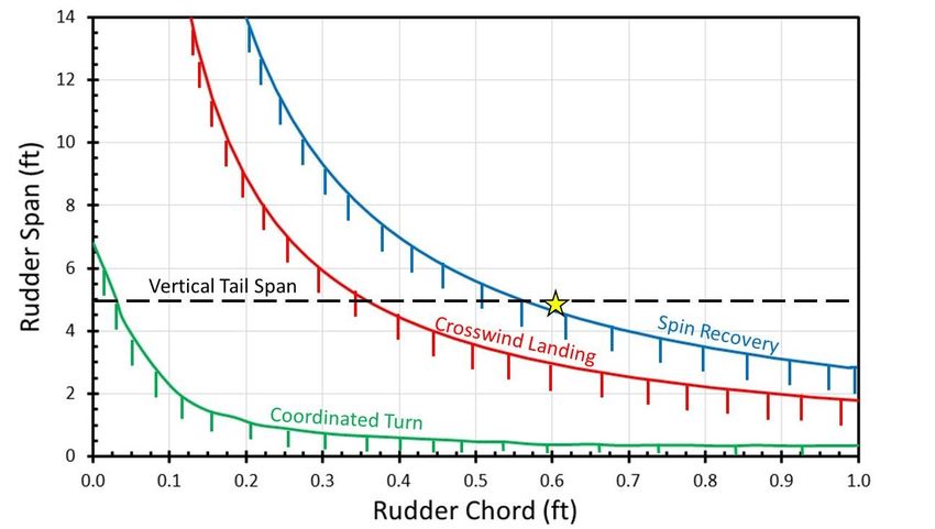
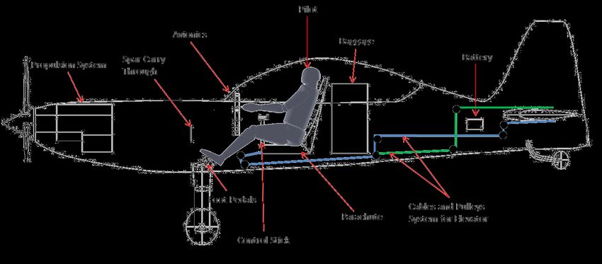
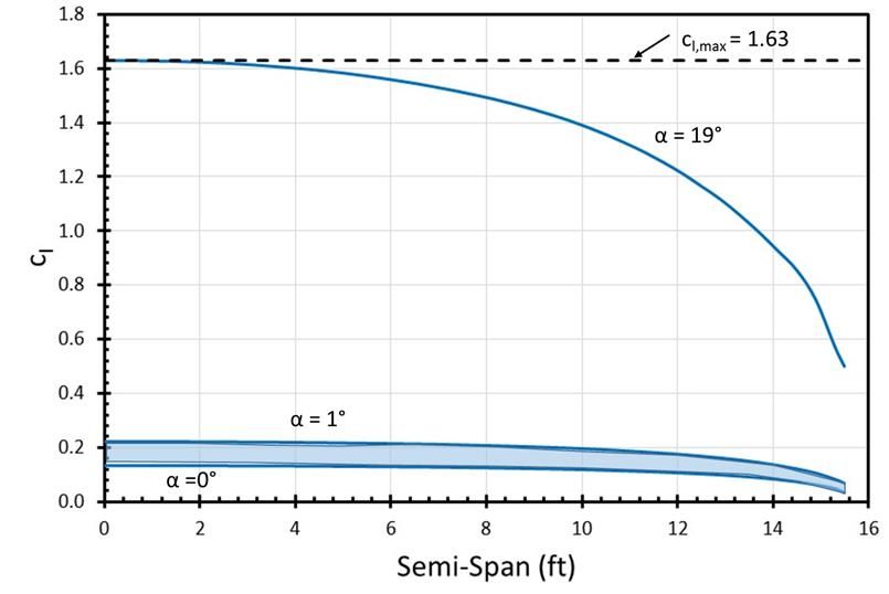
List of Figures
Figure 1: Piston Aircraft Sold and New LSA Registrations ........................................................................................ 14
Figure 2: 2016 Known Compulsory for Intermediate Category .................................................................................. 17
Figure 3: Tempo Competition Mission Profile ............................................................................................................ 19
Figure 4: Constraint Diagram for Tempo .................................................................................................................... 21
Figure 5: Constraint Diagram for Tempo .................................................................................................................... 22
Figure 6: CL,max Constraint Diagram for Tempo .......................................................................................................... 23
Figure 7: CL,max Constraint Diagram for Encore .......................................................................................................... 24
Figure 8: Aesthetics Survey Results ............................................................................................................................ 25
Figure 9: Side-by-Side verses Tandem Seating ........................................................................................................... 25
Figure 10: Landing Gear Placement with Main Track 25-35% of Wingspan ............................................................. 27
Figure 11: Landing Gear Placement ............................................................................................................................ 28
Figure 12: Inboard Profiles .......................................................................................................................................... 29
Figure 13: Location of Fuel in Wings .......................................................................................................................... 30
Figure 14: Root bending moment for a given load limits and wingspans.................................................................... 33
Figure 15: Wing weight verses wingspan .................................................................................................................... 34
Figure 16: Variation of root bending moment in roll with wingspan .......................................................................... 35
Figure 17: Lift Distributions for NACA 23012 Airfoil ............................................................................................... 36
Figure 18: Comparison of Various Taper Ratios ......................................................................................................... 37
Figure 19: Inverted Lift Distribution ........................................................................................................................... 38
Figure 20: Drag Polar for Tempo and Encore ............................................................................................................. 40
Figure 21: Propeller design process ............................................................................................................................. 43
Figure 22: Optimal Propeller Load Curve ................................................................................................................... 44
Figure 23: Thrust and Power at Varying Advance Ratios ........................................................................................... 44
Figure 24: Maximum Thrust Performance .................................................................................................................. 45
Figure 25: Engine Performance ................................................................................................................................... 46
Figure 26: Overall Propulsion System Efficiency ....................................................................................................... 46
Figure 27: V-n Diagram for Tempo ............................................................................................................................. 47
Figure 28: V-n Diagram for Encore ............................................................................................................................. 48
Figure 29: Spar Location in Wing ............................................................................................................................... 49
Figure 30: Tempo Shares Geometric Similarities with P-51 ....................................................................................... 51
Figure 31: Wing Weight Linear Fit to Cessna Dataset ................................................................................................ 54
Figure 32: Horizontal Tail Linear Fit to Cessna Dataset ............................................................................................. 55
Figure 33: Vertical Tail Linear Fit to Cessna Dataset ................................................................................................. 55
Figure 34: Fuselage Linear Fit to Cessna Dataset ....................................................................................................... 56
Figure 36: Loading Diagram for Tempo ...................................................................................................................... 60
Figure 35: Loading Diagram for Encore ...................................................................................................................... 60
Figure 37: X-Plot for Encore ....................................................................................................................................... 62
Figure 38: X-Plot for Tempo ....................................................................................................................................... 62
Figure 39: Trim Diagram for Tempo at Forward CG Limit ........................................................................................ 63
Figure 40: Trim Diagram for Tempo Aft CG Limit .................................................................................................... 63
Figure 41: Trim Diagram for Encore at Aft CG Limit ................................................................................................ 64
Figure 42:Trim Diagram for Encore at Forward CG Limit ......................................................................................... 64
Figure 43: Directional Stability X-plot ........................................................................................................................ 65
Figure 44: Constraint Diagram for Rudder Sizing ....................................................................................................... 67
Figure 45: Part of the rudder unshielded by horizontal tail. ........................................................................................ 68
Figure 46: Necessary Components to find TDPF ........................................................................................................ 68
Figure 47: Determination of Satisfactory Spin Recovery ............................................................................................ 69
Figure 48: Ranging Velocities for Aileron Sizing ....................................................................................................... 70
Figure 49: Sized Ailerons on Wing ............................................................................................................................. 71
Figure 50: The horizontal and vertical tail ................................................................................................................... 71
Figure 51: Flight Envelope for Tempo ........................................................................................................................ 73
Figure 52: Flight Envelope for Encore ........................................................................................................................ 74
Figure 53: Takeoff Field Length for Tempo ................................................................................................................ 75
Figure 54: Takeoff Field Length for Encore ................................................................................................................ 76

 American Institute of Aeronautics and Astronautics
 vi
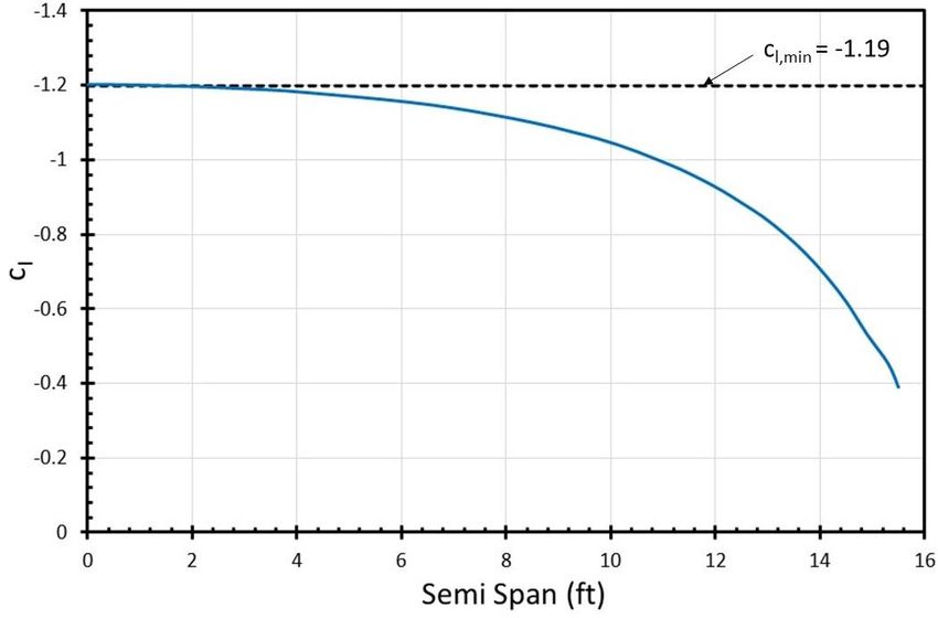
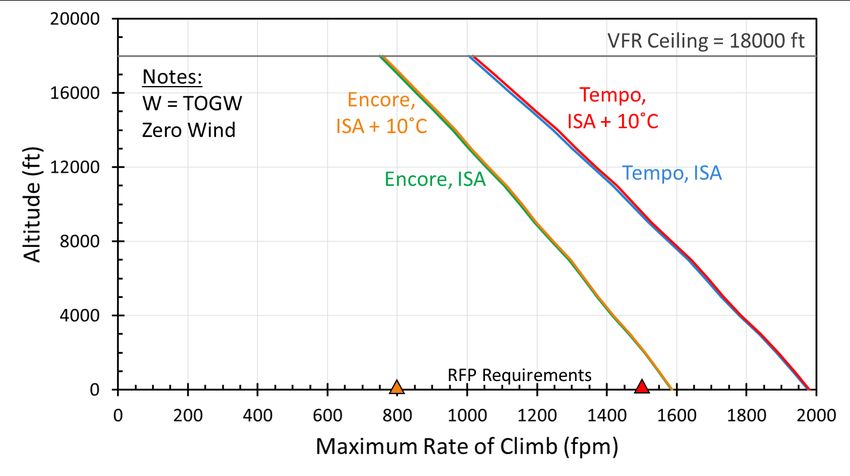
Figure 55: Landing Field Length for Tempo ............................................................................................................... 77
Figure 56: Landing Field Length for Encore ............................................................................................................... 77
Figure 57: Maximum Rate of Climb for Tempo and Encore ....................................................................................... 78
Figure 58: Tempo Fuel Consumption .......................................................................................................................... 78
Figure 59: Fuel Consumption for Encore .................................................................................................................... 79
Figure 60: Tempo Engine RPM and Speed ................................................................................................................. 79
Figure 61: Encore Engine RPM and Speed ................................................................................................................. 79
Figure 62: Payload Range Diagram for Tempo and Encore ........................................................................................ 80
Figure 63: Turn Performance for Tempo ..................................................................................................................... 81
Figure 64: Turn Performance for Encore ..................................................................................................................... 82

 American Institute of Aeronautics and Astronautics
 vii
List of Tables
Table 1: Requirements for Tempo and Encore ............................................................................................................ 11
Table 2: Top Selling LSA Sold in 2014 ...................................................................................................................... 15
Table 3: Top-selling Aerobatic Aircraft Sold in 2014 ................................................................................................. 16
Table 4: Governing Constraints ................................................................................................................................... 20
Table 5: Comparison of Seating Configuration ........................................................................................................... 26
Table 6: Airfoil Trade Study........................................................................................................................................ 32
Table 7: Varying Taper Ratios .................................................................................................................................... 37
Table 8: Drag Component Build-up for Tempo .......................................................................................................... 39
Table 9: Engine Comparison ....................................................................................................................................... 42
Table 10: Propeller Characteristics .............................................................................................................................. 43
Table 11: Component Weight Breakdown .................................................................................................................. 58
Table 12: Varying Payload Weights for Tempo and Encore ....................................................................................... 59
Table 13: Comparison of Volume Coefficients ........................................................................................................... 72

 American Institute of Aeronautics and Astronautics
 viii
Nomenclature AR = aspect ratio AF = activity factor Β = aircraft weight fraction D = drag force CD = drag coefficient CD,0 = zero-lift drag coefficient CD,i = induced drag coefficient Cf = skin friction coefficient CL = lift coefficient CL,cruise = lift coefficient at cruise conditions CL,max = max lift coefficient of the vehicle CL,min = max negative lift coefficient of the vehicle CL,i = integrated design lift coefficient Cn = directional stability ISA = international standard atmosphere L = lift force LDFL = landing field length Lδa = non-dimensional variation of the airplane rolling moment coefficient with aileron deflection Lp = non-dimensional variation of airplane rolling moment g = gravitational acceleration I = inertia Nblade = number of propeller blades Ps = specific excess power P = power provided by the engine q = dynamic pressure S = wing area Swet = wetted area Sh = horizontal tail area Sv = vertical tail area t/c = thickness to chord ratio v = velocity vT = velocity at touchdown W = weight WPropulsion = weight of the propulsion unit WEngine = weight of the engine unit WPropeller = weight of the propeller XCG = center of gravity location Xac = aerodynamic center location α = power lapse β34 = angle of each blade at ¾ the length δa = aileron deflection δr,max = maximum rudder deflection ε = Oswald efficiency λ = taper ratio ηp = propeller efficiency Φ̇ = steady state roll ρ = density μr = coefficient of rolling friction American Institute of Aeronautics and Astronautics ix
11.0 1.0 Tempo
 General Characteristics:
 2.4 3.0 Capacity: One pilot
 Wing Area: 143 ft2
 Max Takeoff Weight: 1087 lbs
 Empty Weight: 738 lbs
 Powerplant: 1 x Lycoming AEIO 230, 116 HP
 Fuel Capacity: 12 US Gallons

11.4 Performance:
 15.0 Climb Rate: 1980 fpm
 5.8 Roll Rate: 360 deg/sec
 Never Exceed Speed: 139 KCAS
 Cruise Speed: 82 KCAS
 1.4 4.2 5.1 Stall Speed: 39 KCAS
 Max Range: 355 nm

 Legend:
7.6 Center of Gravity
 Aerodynamic Center
 Center of Pressure
 5.1 1.0
 11.3
 5.0
 9.3

 0.6

 6.4 5.7
 31.0 8.3
 22.8
 American Institute of Aeronautics and Astronautics
 viii
12.0 1.2
 Encore
 2.4 3.0 General Characteristics:
 Capacity: One pilot
 Wing Area: 143 ft2
 Max Takeoff Weight: 1297 lbs
 Empty Weight: 767 lbs
 Powerplant: 1 x Lycoming AEIO 230, 116 HP
 Fuel Capacity: 12 US Gallons
11.7
 Performance:
 15.0 Climb Rate: 1590 fpm
 5.8 Roll Rate: 360 deg/sec
 Never Exceed Speed: 150 KCAS
 Cruise Speed: 82 KCAS
 4.2 5.1
 1.4 Stall Speed: 42 KCAS
 Max Range: 355 nm

 Legend:
7.2 Center of Gravity
 Aerodynamic Center
 Center of Pressure

 1.0
 11.3
 5.0
 9.3

 0.6
 6.4 5.2
 8.0
 31.0 22.8
 American Institute of Aeronautics and Astronautics
 ix
1 Introduction
 The 2015-2016 AIAA Undergraduate Team Design Competition Request for Proposal (RFP) 1 calls for an

aerobatic light sport aircraft family. This two-member family will have both single and two seat variants. The single-

seat variant will be competitive in the International Aerobatic Club (IAC) intermediate category, while the two seat

model serves as a general sport and aerobatic trainer. The entry into service (EIS) for the first model is 2020 and the

second model is in 2021. For LSA, The Federal Aviation Administration (FAA) and ASTM International2 require

the unique constraint of a maximum speed of 120 knots calibrated airspeed, limiting the upper end of the flight

envelope. This maximum speed requirement coupled with the RFP specific requirement of a 1500fpm climb rate

creates an interesting design problem. Avem has designed a unique propulsion system that will achieve the desired

performance throughout the entire flight envelope, discussed further in Section 7. The key objective of the aircraft

family is to have a high level of commonality between the two variants that will help minimize development and

production costs. In order to meet this objective, Avem has chosen a specific configuration that will allow for a high

degree of commonality between the two aircraft, discussed in Section 9.3. Aerobatic performance is of the utmost

importance to Avem so an in-depth performance analysis has been completed to demonstrate superior qualities of

the aircraft family, discussed in Section 11. A detailed weight breakdown ensures compliance with the ASTM

International requirement of a maximum weight of 1320lbs, tabulated in Section 9. Avem Dynamics presents Tempo

and Encore, the single-seat and two seat aircraft respectively, as the solution to the new, modern aerobatic LSA. To

begin the discussion of the aircraft family, the requirements and objectives are further outlined in Section 1.1.

1.1 REQUIREMENTS
 Both variants must comply with ASTM International, FAA, and RFP specific requirements, which are

shown in Table 1. Important design objectives from the RFP, dealing with commonality, aesthetics, and

manufacturing as also discussed. More requirements were derived throughout the design process.

1.1.1 RFP REQUIREMENTS
 The RFP states that both aircraft must meet the FAA LSA definition and ASTM International Standards for

an LSA, which are described in Table 1 as Requirements 1.0 – 8.0. Requirement 3.0 is unique to LSA since most

aircraft have a minimum speed requirement and not a maximum speed requirement. This requirement, in

conjunction with the desired climb rate, are key when deciding what propulsion system to incorporate, Requirements

 American Institute of Aeronautics and Astronautics
 10
RBS Requirement
 1.0 The aircraft shall have a gross takeoff weight less than or equal to 1,320 lbs (1,430 lbs for seaplanes).
 2.0 The aircraft shall have a maximum stall speed of 45 knots CAS in clean configuration.
 3.0 The aircraft shall have a maximum speed in level flight of 120 knots CAS.
 4.0 The aircraft shall have a maximum capacity of two people.
 5.0 The aircraft shall have only one single piston engine that meets the LSA ASTM standards presently or plans to meet them by EIS.
 6.0 The aircraft shall have either a fixed-pitch or ground adjustable propeller.
 7.0 The aircraft’s cabin shall be unpressurized.
 8.0 The aircraft shall have fixed landing gear, except for seaplanes.
 9.0 The avionics shall meet LSA ASTM standards presently or plans to meet them by EIS.
 10.0 The single seat aircraft shall have a payload of a 230 lb pilot, a 15 lb parachute, and 1.5 hours of fuel.
 10.1 The single seat aircraft shall withstand +6/-5 G limit loads with the payload capacity described in 10.1
 10.2 The single seat aircraft shall have a minimum ferry range of 300 nmi with a 30 minute fuel reserve.
 10.3 The single seat aircraft shall have a climb rate of at least 1,500 fpm at sea level (International Standard Atmosphere (ISA) + 10° C )
 10.4 The single seat aircraft shall have a maximum takeoff and landing field length of 1,200 ft over a 50 ft obstacle to a dry pavement runway (sea level ISA + 10° C).
10.5.1 The single seat aircraft takeoff and landing performance shall be shown at ISA + 10° C at 5,000 ft Mean Sea Level (MSL).
10.5.2 The single seat aircraft takeoff and landing performance shall be shown for a grass field at sea level (ISA + 0° C).
 The single seat aircraft shall have a minimum roll rate of 180 degrees per second at either the maximum level cruise speed or the maximum speed of 120 knots
10.6
 CAS, whichever is slower.
 10.7 The single seat aircraft must have space for 30 lb and 4 cubic feet of baggage for the ferry missions.
 10.8 The single seat aircraft’s performance shall be competitive in Internal Aerobatic Club intermediate category competition.
 11.0 The two seat aircraft shall have a payload of two 200 lb pilots, two 15 lb parachutes, and 1.5 hours of fuel.
 11.1 The two seat aircraft shall withstand +6/-3 G limit loads with the payload capacity described in 11.1
 11.2 The two seat aircraft shall have a minimum ferry range of 250 nmi with a 30 minute fuel reserve.
 11.3 The two seat aircraft shall have a climb rate of at least 800 fpm at sea level ( ISA + 10° C )
 11.4 The two seat aircraft shall have a maximum takeoff and landing field length of 1,500 ft over a 50 ft obstacle to a dry pavement runway (sea level ISA + 10° C).
11.5.1 The two seat aircraft takeoff and landing performance shall be shown at ISA + 10° C at 5,000 ft MSL.
11.5.2 The two seat aircraft takeoff and landing performance shall be shown for a grass field at sea level (ISA + 0° C).
 11.6 The two seat aircraft must have space for at least 30 lb and 6 cubic feet of baggage for the ferry missions.
 12.0 The aircraft family shall accommodate a pilot (and passenger) at most 6 ft tall.
 13.0 The aircraft family shall be capable of flying inverted (-1G) for at least 5 minutes.
 Table 1: Requirements for Tempo and Encore

 American Institute of Aeronautics and Astronautics
 11
10.3 and 11.3 respectively. An interesting tradeoff occurs between the high climb rate requirement and the low

maximum speed requirement, and this tradeoff is a main driving factor during the design process. The single-seat

variant has a climb rate of 1,500fpm at sea level, while the two seat variant is slightly more relaxed at 800fpm.

These requirements pertain most directly to selecting an engine and sizing an appropriate propeller.

 Requirement 10.8, which requires the single-seat variant to have competitive aerobatic performance, sets

this aircraft apart from the two seat variant. The single-seat variant must be competitive in the intermediate category

of the IAC competitions, implying that it should be able to perform basic maneuvers such as spins, loops, turns, and

rolls as well as snap rolls and inverted maneuvers, discussed further in Section 3. The two seat variant serves as an

aerobatic trainer and general sport aircraft and must be able to perform the same maneuvers as the single-seat for

training purposes, but not at a competitive level.

1.1.2 DERIVED REQUIREMENTS
 Certain requirements, not specified by ASTM International, FAA, or RFP, arise from the previously stated

requirements. The first of these derived requirements is the maximum lift coefficient for the aircraft, CL,max. This

derived requirement is taken from the requirements for landing field length for Tempo and stall speed for Encore.

Because CL,max depends on wing loading, all point performance constraints were considered for the mentioned

requirements and CL,max was derived, as described in Section 4.2. Another derived requirement is the type of airfoil

used for the wing. The inverted flight requirement from the RFP influences the airfoil choice to a more symmetric

design for the better performance characteristics at negative values of lift, examined more closely in Section 6.1. A

third derived requirement to improve aerobatic performance includes a desire for sharp stall characteristics from the

planform of the wing. To perform sharp stall induced maneuvers commonly experienced in intermediate category

competition, like a snap roll, it is necessary for the aircraft to stall all at once to accurately execute the maneuver.

1.2 DESIGN OBJECTIVES
 While not requirements, the design objectives are criteria desirable in the aircraft. The first design objective

stated in the RFP is for the re-use of at least 75% of the airframe and systems by weight for both the single and two

seat variants. This commonality between the two aircraft does not include the propulsion system, engine or

propeller. This objective is interpreted as the main structure and systems of Encore should be 75% common with the

main structure and systems of Tempo. In this way, Tempo will come first in the design process and Encore will

 American Institute of Aeronautics and Astronautics
 12
follow. Tempo was chosen as the comparison aircraft in order to prioritize the aerobatic performance and achieve

the desired commonality with a lower total weight to normalize the aircraft.

 The second design objective is to have visually appealing aircraft. Since Avem Dynamics is entering the

market as a new company, it is the plan that the company will established itself as a stylish option to the LSA

market. The more aircraft that are sold, the more money Avem Dynamics will make and be able to turn a profit.

Because "visually appealing" is somewhat arbitrary, small scale market research is performed to decide what

constitutes a “pretty” aircraft to the public. This research takes into account non-customers, such as students, to

achieve a rudimentary study on what makes an aircraft appealing. In addition, an interview with Dan Rhin,4 designer

of the DR-107 and DR-109 (aerobatic, LSA aircraft) was conducted to determine desirable aesthetics for

competitive aircraft, further discussed in Section 5.1.

 The next design objective is to minimize maintenance cost of the aircraft. This objective will make the

aircraft more marketable since maintaining the aircraft is what the customer will spend the most money on. This

objective is closely tied to how the aircraft is manufactured and is thus closely tied to the next design objective.

 The last design objective is to minimize production costs of the aircraft. Once again, Avem Dynamics is

new to the market and so most of the startup capital will go into deciding where and how the aircraft will be

manufactured. The facilities, expertise on manufacturing, laborers, and materials will all have to be established

before production can begin on the aircraft, regardless of the materials chosen or manufacturing techniques chosen.

Thus, throughout the design process, manufacturing techniques and materials play a role in the decision process. The

materials will affect the manufacturing technique needed and is looked at more closely in Section 8.3.

2 Market Analysis
 As a new company entering the LSA market, it is crucial to gain a better understanding of the competition;

therefore, a market analysis was conducted in order to gain more knowledge of the LSA and aerobatic markets and

to ultimately to develop reasonable sales goals. Certain characteristics were determined: how many LSA are sold per

year, the number of LSA sold per company, and which companies are successful and why. These characteristics

were examined using data from the General Aviation Manufacturers Association3 and Johnson’s LSA market

information website.5 Once the overall climate is determined, the company can evaluate if there is a demand for a

new aerobatic LSA.

 American Institute of Aeronautics and Astronautics
 13
A good place to start in

a market analysis is determining

how many LSA are sold per year

to gain an understanding of the

size of the LSA market. Figure 1

plots the number of LSA

registered with the FAA each

year along with the number of

piston engine aircraft sold each Figure 1: Piston Aircraft Sold and New LSA Registrations

year. New LSA registrations are a representation of how many LSA are manufactured, and thus sold in a given year.

The plot shows that 199 new LSA were registered in 2014. The number of total and single piston engine aircraft sold

per year are presented alongside the new LSA registrations. Since LSA are single piston aircraft, this comparison

gives an idea of the overall success rate of this type of aircraft to a more general market. It can be seen from the

figure that both the LSA and piston engine markets took large hits due to the recession in 2007-2009 and still have

not fully recovered. Taking a closer look at the results of the recession, from the year 2007 to the year 2009, the total

and single piston engine aircraft markets decreased by nearly 70%, while new LSA registrations only went down by

about 50%. These numbers infer that although the overall piston engine market took a massive hit during the

recession, LSA did not suffer as much. This observation is interesting because LSA are bought primarily for leisure

purposes, and during a financial crisis the first expenses people cut out are leisure expenses; however, the LSA

market did not decrease as significantly as might be expected. One possibility for this difference is that due to the

recession, aircraft customers decided to buy the cheaper LSA over a larger piston engine aircraft. This decision

could be an indication that although the LSA market is small and relatively new, people are still interested in buying

them even in economic struggles.

 Now that an understanding of the overall trend of the LSA market has been formulated, the likelihood of

company success within this market can be evaluated. Table 2 shows a list of companies that registered the most

LSA with the FAA in 2014. In addition to the number of aircraft registered, the table also presents the year of the

companies' founding, the most common model of each company, and the base price of each of the models. There are

a number of important takeaways from this table. First, it should be noted that the RFP states that an aerobatic LSA

 American Institute of Aeronautics and Astronautics
 14
Table 2: Top Selling LSA Sold in 20144,5

 Year Cost of Main Aircraft
 Manufacturer Main Model
 Founded Model Registered
 CubCrafters 1980 Carbon Cub SS $172,990 50
 Van's 1973 RV-12 $123,000 26
 Progressive Aerodyne 1991 SeaRey $125,000 19
 Flight Design 1988 CTLSi $156,500 16
 Tecnam 1986 P92 $130,999 14
 Aeropro (Aerotek) 1983 A240/220 $88,950 11
 American Legend 2005 Legend Cub $136,900 10
 Czech Sport Aircraft 1934 SportCruiser $119,000 9
must be designed, yet none of the leading LSA in the market are aerobatic LSA. Therefore, it can be concluded that

this specific type of aircraft is underrepresented within the market, and Avem Dynamics can take advantage of this

and become a leader with unique class of aircraft.

 Also, all the aircraft in Table 2 are two seat LSA which gives the indication that single-seat variants are

also underrepresented in the market. CubCrafters only registered 50 aircraft in 2014 and the majority of companies

registered between 10 and 20 in 2014. This data demonstrates that Avem Dynamics will need to be profitable selling

10-20 aircraft per year. However, the minimum production rate in the RFP is 4 aircraft per month (48 per year).

Therefore, Avem Dynamics will aim to be profitable selling 48 aircraft per year. Looking at the cost of the main

models of each company, most aircraft are sold for $100,000 to $200,000. These prices give an indication for an

approximate range in which the designed aircraft should be sold in order to be competitive in this market.

 Many of the companies listed in Table 2 are well established and have existed for a number of decades. As

a new company, it would be beneficial to investigate how new companies attempting to enter this market have fared.

An example of a new company attempting to enter this market is Icon Aircraft. Icon has recently certified their new

LSA, the A5. Although they have not sold any aircraft yet, they have recently entered production and already have a

backlog of over 1,000 orders. This success demonstrates that LSA customers are not deterred by a new and

unproven company as long as the product is intriguing and worth buying. As a result, it can be concluded that with a

strong product a new company can have great success in the LSA market.

 Since Tempo and Encore are aerobatic aircraft, it is important to also research the aerobatic market. Table 3

lists the most successful aerobatic aircraft companies from 2014. Note that none of the bestselling aerobatic aircraft

 American Institute of Aeronautics and Astronautics
 15
qualify as LSA. Therefore, once again, it can be concluded that the market of aerobatic LSA is underrepresented

within both the LSA and aerobatic markets. Looking at Table 3 there are some key highlights to notice. First,

aerobatic aircraft sell significantly more than LSA. All of the aerobatic aircraft listed sell for more than $200,000.

This increase in price indicates that if an aerobatic LSA is sold around the average price of other LSA, it will be a

relatively inexpensive competitor in the aerobatic market. Another interesting fact is that the most successful

aerobatic aircraft companies sell less product than the leading LSA companies; but, the moderately successful

companies sell in the range of 10 to 20 aircraft each year so it is reasonable to assume that aerobatic LSA will sell in

that same range.

 Table 3: Top-selling Aerobatic Aircraft Sold in 20143.4

 Manufacturer Main Model Cost of Main Model Number Sold
 Extra EA-300 $350,000 31
 American Champion Super Decathlon $238,900 30
 WACO Classic Aircraft 2T-1A-2 (Great Lakes) $245,000 11
 XtremeAir XA42 $240,000 9

 There are a number of conclusions that can be drawn after conducting the market analysis. First, the LSA

market was not hit as hard during the recession, which indicates that people are still willing to buy LSA even during

financial struggles. Additionally, Avem Dynamics can aim to sell 4 aircraft per month – achieving the RFP

objective, while still falling within the range of yearly sales of existing LSA companies. Using Icon Aircraft’s new

A5 as an example, a new company can have great success in the LSA market with a strong enough product. Finally,

after investigating the LSA and aerobatic markets, it was determined that the specific category of aerobatic LSA was

not strongly represented in either market. Therefore, by designing aerobatic LSA, Avem Dynamics can hopefully

have great success, and become a leader in a unique class of aircraft by simply providing a product that was

previously underappreciated in both LSA and aerobatic markets.

3 Aerobatic Competition
 The RFP states that Tempo must be competitive within the International Aerobatic Club’s intermediate

category. This section describes this competition level and gives an expected competition mission profile.

 American Institute of Aeronautics and Astronautics
 16
3.1 IAC INTERMEDIATE CATEGORY
 Within the International Aerobatic Club (IAC) there are five categories of competition: primary, sportsman,

intermediate, advanced, and unlimited. The intermediate category falls within the mid-range of difficulty where the

pilots are beginning to be tested on more complex maneuvers and combinations of maneuvers within a sequence.

From this it can be inferred that Tempo and Encore will be flown by experienced pilots or at least accompanied by

one. This category includes maneuvers consisting of the basic maneuvers such as spins, loops, rolls, and turns with

the addition of the snap roll and inverted figures. A snap roll is a rapid horizontal spin that is induced by a rapid

pitch input followed by a rapid yaw input. Thus, the aircraft must be able to fly inverted and have competitive roll

rates which are requirements stated in the RFP.

 During the competition, an intermediate

category pilot is expected to perform a known,

unknown, and free program. The known program

is published each year by either the international

or national aerobatic club before any of the

competitions. The 2016 known compulsory6 for

the intermediate category is shown in Figure 2 in

Aresti symbols, where the triangles represents a

positive g snap roll, the red lines represented

inverted flight, and the arrows represent aileron

roll. The sequence illustrates a typical

intermediate category routine that includes

various loops, snap rolls, inverted flight, and other

basic maneuvers. The unknown program is

revealed to the pilot the day of the competition.

This program is meant to test the pilot’s ability to

fly a sequence that they have never flown. A free

program is designed for the pilot to demonstrate
 Figure 2: 2016 Known Compulsory for Intermediate Category
style, creativity, and flying skills through a

 American Institute of Aeronautics and Astronautics
 17
sequenced designed by the pilot. However, this sequence is limited to the maneuvers allowed in the intermediate

category. Therefore, the aircraft must not only have enough fuel and power to perform the required maneuvers, but

also adequately sized control surfaces and proper structure. These characteristics will be assessed in further detail

throughout this document.

 During a competition, all the programs must be performed within the aerobatic box to insure safety and to

allow the aircraft to always remain in the judges’ eyesight. The box is 3,280ft long and 3,280ft wide.7 The height of

the box varies based on level of competition. For the intermediate category the lower limit of the box is 1,200 feet

above the ground and the upper limit is 3,500ft above the ground. White markers are placed on the ground to mark

the corners of the box, but if the pilot exceeds these boundaries they are penalized and points are deducted from the

final score. Therefore, it is important that the pilot is able to see the markers during the entire sequence. There is a

buffer zone of 164ft along each axis beyond the marked aerobatic box boundaries. Each excursion into the buffer

zone is penalized. One nautical mile beyond the buffer zone is the deadline line, or safety buffer zone. A greater

penalty is applied if the pilot crosses this line. If any of the figures are flown entirely outside the box, then the pilot

receives an automatic zero score.

 There are between 3 and 9 grading judges at any competition. The grading judges assess the quality of each

figure flown and assign a score between zero and ten to the pilots, with 10 being flawless. A zero can be given if a

figure is flown incorrectly. A presentation score is given at the end of a sequence to reflect the placement of the

sequences throughout the aerobatic box. The pilot’s skills mostly determine the quality of the aerobatic maneuvers,

but the shape and aesthetics of the aircraft enhance the overall appearance of the maneuvers. Thus, the aircraft must

aid the pilot in executing the maneuvers.

3.2 AEROBATIC MISSION PROFILE
 The single seat is expected to be used primarily as a competitive aerobatic aircraft. For this reason, an

aerobatic mission profile has been developed to depict a typical mission of Tempo. Figure 3 shows what the mission

for an aerobatic competition would look like, specifically in the intermediate category of the IAC. The aircraft will

most likely takeoff at the airport at which the competition is being held and loiter for approximately one minute until

it is that pilot’s turn to compete. The pilot will fly over to the competition area and into the aerobatic box. The

routine will last about four minutes and then the pilot will exit the aerobatic box and land. When flying during the

competition, the engine will be at maximum continuous power almost the entire time, this leads to a cruise speed of

 American Institute of Aeronautics and Astronautics
 18
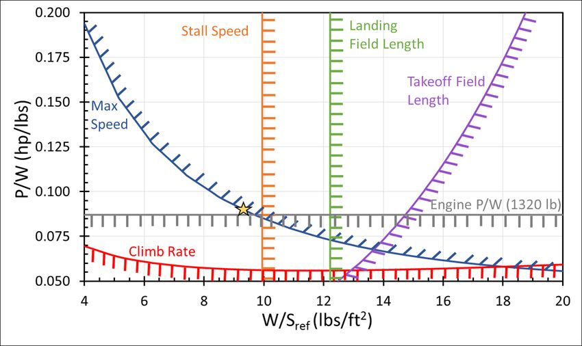
120 KCAS for competition. Tempo is expected to have a competition weight of 1005 pounds, based on needing fuel

for about 40 minutes of flight time (including the 30 minute fuel reserve) as well as having a pilot that is the

maximum weight the RFP requires which is 230 pounds.

 Figure 3: Tempo Competition Mission Profile

4 Aircraft Sizing
 This section describes the sizing choices for Tempo and Encore, which are determined by plotting the

major constraints with respect to wing loading and power-to-weight. Then from the constraint diagrams the wing

loading and power-to-weight for each aircraft are selected. In order to maintain commonality between aircraft, it is

desired to select design points for each aircraft that yield the same wing area and propulsion system for the aircraft.

The power-to-weight selected is based on the power output of the selected engine, the Lycoming AEIO-233 and the

weight estimates of the aircraft.

4.1 CONSTRAINT DIAGRAM
 The objective of the constraint diagram is to determine a design point that yields the power-to-weight ratio

and wing loading (weight-to-wing area ratio) of the aircraft. The specific excess power equation is used since it

involves both power-to-weight and wing loading. This equation incorporates the requirements and constraints from

the RFP, which are listed in Table 4. The requirements are expressed by creating contours of either specific excess

power (for maximum speed and climb rate), simplified takeoff and landing integrals for the takeoff and landing

 American Institute of Aeronautics and Astronautics
 19
You can also read