Dell EMC PowerScale: Network Design Considerations - Abstract
←
→
Page content transcription
If your browser does not render page correctly, please read the page content below
Technical White Paper

 Dell EMC PowerScale: Network Design
 Considerations
                         Abstract
                         This white paper explains design considerations of the Dell EMC™
                         PowerScale™ external network to ensure maximum performance and an optimal
                         user experience.

                         May 2021

H16463.20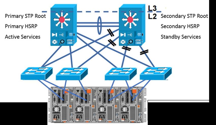
Revisions

Revisions
            Date                 Description
            March 2017           Initial rough draft

            July 2017            Updated after several reviews and posted online

            November 2017        Updated after additional feedback. Updated title from “Isilon Advanced Networking
                                 Fundamentals” to “Isilon Network Design Considerations.” Updated the following
                                 sections with additional details:

                                 •   Link Aggregation
                                 •   Jumbo Frames
                                 •   Latency
                                 •   ICMP & MTU
                                 •   New sections added:
                                 •   MTU Framesize Overhead
                                 •   Ethernet Frame
                                 •   Network Troubleshooting

            December 2017        Added link to Network Stack Tuning spreadsheet

                                 Added Multi-Chassis Link Aggregation
            January 2018         Removed switch-specific configuration steps with a note for contacting manufacturer

                                 Updated section title for Confirming Transmitted MTUs

                                 Added OneFS commands for checking and modifying MTU

                                 Updated Jumbo Frames section
            May 2018             Updated equation for Bandwidth Delay Product

            August 2018          Added the following sections:

                                 • SyncIQ Considerations
                                 • SmartConnect Considerations
                                 • Access Zones Best Practices

            August 2018          Minor updates based on feedback and added ‘Source-Based Routing Considerations’

            September 2018       Updated links

            November 2018        Added section ‘Source-Based Routing & DNS’

            April 2019           Updated for OneFS 8.2: Added SmartConnect Multi-SSIP

            June 2019            Updated SmartConnect Multi-SSIP section based on feedback.

            July 2019            Corrected errors

2      Dell EMC PowerScale: Network Design Considerations | H16463.20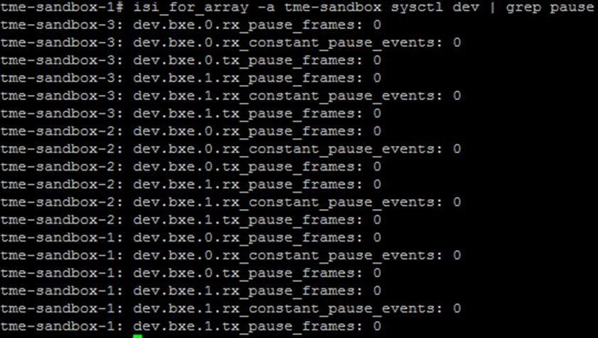
Acknowledgements

                 Date                       Description
                 August 2019                Updated Ethernet flow control section

                 January 2020               Updated to include 25 GbE as front-end NIC option.

                 April 2020                 Added ‘DNS and time-to-live’ section and added ‘SmartConnect Zone Aliases as
                                            opposed to CNAMEs’ section.
                 May 2020                   Added ‘S3’ section under ‘Protocols and SmartConnect allocation methods’, updated
                                            ‘Isilon’ branding to ‘PowerScale’, and added ‘IPMI’ section.
                 June 2020                  Added ‘QoS’ and ‘Software-Defined Networking’ sections. Updated the ‘NFSv4’
                                            section with Kerberos and updated the ‘IP Address quantification’ section.
                 July 2020                  Added ‘SmartConnect service name’ section.

                 August 2020                Added ‘Isilon 6th generation 1 GbE interfaces’ and ‘VLAN and interface MTU’ sections.
                                            Updated ‘IPMI’ section.
                 September 2020             Updated ‘DNS delegation best practices’ and ‘SmartConnect in isolated network
                                            environments’ sections.
                 February 2021              Updated ‘IPMI’ section.

                 May 2021                   Added IPv6 Router Advertisements and Duplicate Address Detection sections.

Acknowledgements
               Author: Aqib Kazi

The information in this publication is provided “as is.” Dell Inc. makes no representations or warranties of any kind with respect to the information in this
publication, and specifically disclaims implied warranties of merchantability or fitness for a particular purpose.

Use, copying, and distribution of any software described in this publication requires an applicable software license.

This document may contain certain words that are not consistent with Dell's current language guidelines. Dell plans to update the document over
subsequent future releases to revise these words accordingly.

This document may contain language from third party content that is not under Dell's control and is not consistent with Dell's current guidelines for Dell's
own content. When such third party content is updated by the relevant third parties, this document will be revised accordingly

Copyright © 2021 Dell Inc. or its subsidiaries. All Rights Reserved. Dell Technologies, Dell, EMC, Dell EMC and other trademarks are trademarks of Dell
Inc. or its subsidiaries. Other trademarks may be trademarks of their respective owners. [4/27/2021] [Technical White Paper] [H16463.20]

3         Dell EMC PowerScale: Network Design Considerations | H16463.20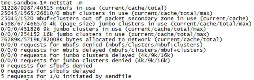
Table of contents

Table of contents
    Revisions ..................................................................................................................................................................... 2
    Acknowledgements ...................................................................................................................................................... 3
    Table of contents ......................................................................................................................................................... 4
    Executive summary...................................................................................................................................................... 8
    Note to readers ............................................................................................................................................................ 8
    1     Network architecture design................................................................................................................................... 9
          1.1      General network architecture considerations ................................................................................................ 9
          1.2      Triangle looped topology ............................................................................................................................ 10
          1.3      Link aggregation ......................................................................................................................................... 11
          1.3.1 Multi-chassis link aggregation ..................................................................................................................... 12
    2     Latency, bandwidth, and throughput .................................................................................................................... 13
          2.1      Latency ...................................................................................................................................................... 13
          2.2      Bandwidth and throughput .......................................................................................................................... 14
          2.2.1 Bandwidth delay product ............................................................................................................................ 14
          2.3      PowerScale network stack tuning ............................................................................................................... 15
    3     Ethernet flow control ............................................................................................................................................ 17
          3.1      Checking for pause frames ......................................................................................................................... 17
          3.1.1 4th and 5th generation Isilon nodes .............................................................................................................. 18
          3.1.2 6th generation Isilon nodes.......................................................................................................................... 18
    4     SyncIQ considerations ......................................................................................................................................... 19
          4.1      SyncIQ disaster recovery with SmartConnect ............................................................................................. 19
          4.2      Replication traffic over dedicated WAN links ............................................................................................... 19
    5     Quality of Service (QoS) ...................................................................................................................................... 20
    6     Software-Defined Networking .............................................................................................................................. 21
    7     PowerScale OneFS ports .................................................................................................................................... 22
    8     SmartConnect considerations .............................................................................................................................. 23
          8.1      SmartConnect network hierarchy ................................................................................................................ 23
          8.2      Load balancing ........................................................................................................................................... 24
          8.3      Static or dynamic IP address allocation ...................................................................................................... 25
          8.4      Dynamic failover......................................................................................................................................... 25
          8.4.1 Dynamic failover examples ......................................................................................................................... 26
          8.5      Protocols and SmartConnect allocation methods ........................................................................................ 28
          8.5.1 SMB ........................................................................................................................................................... 28
          8.5.2 NFS ........................................................................................................................................................... 29

4            Dell EMC PowerScale: Network Design Considerations | H16463.20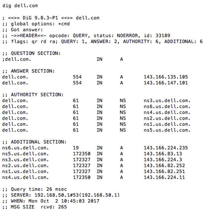
Table of contents

        8.5.3 HDFS ......................................................................................................................................................... 29
        8.5.4 S3 .............................................................................................................................................................. 29
        8.5.5 Suggested zones by protocol...................................................................................................................... 30
        8.6     IP address quantification ............................................................................................................................ 31
        8.7     SmartConnect service name ...................................................................................................................... 32
        8.8     SmartConnect node suspension ................................................................................................................. 33
        8.9     SmartConnect and Reverse DNS ............................................................................................................... 33
        8.10 DNS delegation best practices.................................................................................................................... 34
        8.10.1       Delegate to address (A) records, not to IP addresses ............................................................................. 34
        8.10.2       SmartConnect zone aliases as opposed to CNAMEs.............................................................................. 34
        8.10.3       One name server record for each SmartConnect zone name or alias...................................................... 34
        8.10.4       Multiple DNS resolvers in a groupnet...................................................................................................... 35
        8.11 SmartConnect in isolated network environments......................................................................................... 36
        8.12 SmartConnect DNS, subnet, and pool design ............................................................................................. 36
        8.12.1       SmartConnect zone naming ................................................................................................................... 37
        8.12.2       SmartConnect with multiple node pools or types..................................................................................... 37
        8.13 Where the SmartConnect Service IP (SSIP) runs (pre OneFS 8.2) ............................................................. 38
        8.14 SmartConnect Multi-SSIP........................................................................................................................... 40
        8.14.1       Configuring OneFS for SmartConnect Multi-SSIP ................................................................................... 41
        8.14.2       Configuring a DNS server for SmartConnect multi-SSIP ......................................................................... 42
        8.14.3       SSIP node assignment ........................................................................................................................... 44
        8.15 DNS and time-to-live .................................................................................................................................. 45
        8.15.1       Microsoft Windows DNS......................................................................................................................... 45
        8.15.2       BIND DNS.............................................................................................................................................. 45
        8.16 Other SmartConnect considerations ........................................................................................................... 47
    9   Ethernet, MTU, and IP overhead.......................................................................................................................... 48
        9.1     Ethernet packet .......................................................................................................................................... 48
        9.2     Ethernet payload ........................................................................................................................................ 49
        9.3     Jumbo frames ............................................................................................................................................ 49
        9.4     IP packet overhead .................................................................................................................................... 50
        9.4.1 Example 1: Standard 1500-byte payload – IPv4/TCP.................................................................................. 50
        9.4.2 Example 2: Jumbo 9000-byte payload – IPv4/TCP ..................................................................................... 51
        9.4.3 Example 3: Standard 1500-byte payload – IPv4/TCP/Linux timestamp ....................................................... 51
        9.4.4 Example 4: Jumbo 9000-byte payload – IPv4/TCP/Linux timestamp ........................................................... 51
        9.5     Data payload to Ethernet frame efficiency................................................................................................... 52
        9.6     ICMP and MTU with OneFS ....................................................................................................................... 52

5         Dell EMC PowerScale: Network Design Considerations | H16463.20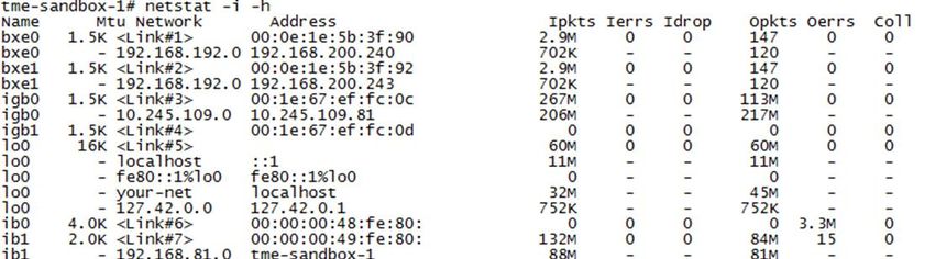
Table of contents
9.7 OneFS MTU commands ............................................................................................................................. 53
9.8 VLAN and interface MTU............................................................................................................................ 53
9.9 Confirming transmitted MTU ....................................................................................................................... 53
10 Access Zones best practices ............................................................................................................................... 54
10.1 System Zone .............................................................................................................................................. 54
10.2 Root Based Path ........................................................................................................................................ 54
11 Source-Based Routing considerations ................................................................................................................. 56
11.1 Source-Based Routing and DNS ................................................................................................................ 57
12 Isilon 6th generation 1 GbE interfaces................................................................................................................... 58
13 Intelligent Platform Management Interface ........................................................................................................... 59
13.1 Configuring IPMI ........................................................................................................................................ 60
13.2 IPMI SoL on PowerScale nodes ................................................................................................................. 61
13.2.1 Configure serial devices ......................................................................................................................... 61
13.2.2 iDRAC SoL permission........................................................................................................................... 61
13.3 Accessing IPMI .......................................................................................................................................... 62
13.4 Troubleshooting IPMI ................................................................................................................................. 62
14 IPv6..................................................................................................................................................................... 63
14.1 Why IPv6?.................................................................................................................................................. 63
14.1.1 Security.................................................................................................................................................. 63
14.1.2 Efficiency ............................................................................................................................................... 63
14.1.3 Multicast ................................................................................................................................................ 63
14.1.4 Quality of Service ................................................................................................................................... 63
14.2 IPv6 addressing ......................................................................................................................................... 64
14.3 IPv6 header................................................................................................................................................ 65
14.4 IPv6 to IPv4 translation............................................................................................................................... 65
14.5 Router Advertisements ............................................................................................................................... 66
14.6 Duplicate Address Detection ...................................................................................................................... 67
15 Network troubleshooting ...................................................................................................................................... 68
15.1 Netstat ....................................................................................................................................................... 68
15.1.1 Netstat ................................................................................................................................................... 68
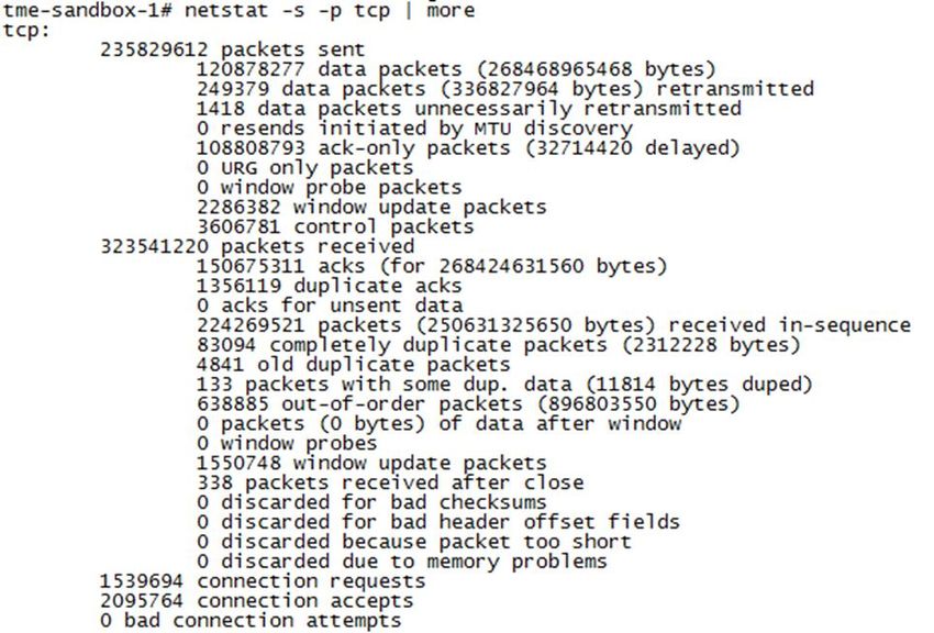
15.1.2 netstat -s -p tcp ...................................................................................................................................... 69
15.1.3 netstat -i ................................................................................................................................................. 70
15.1.4 netstat -m............................................................................................................................................... 71
15.2 InsightIQ external network errors ................................................................................................................ 71
15.3 DNS ........................................................................................................................................................... 73
A Supported network optics and transceivers .......................................................................................................... 75
6 Dell EMC PowerScale: Network Design Considerations | H16463.20
Table of contents

    B   Technical support and resources ......................................................................................................................... 76
        B.1     Related resources ...................................................................................................................................... 76

7         Dell EMC PowerScale: Network Design Considerations | H16463.20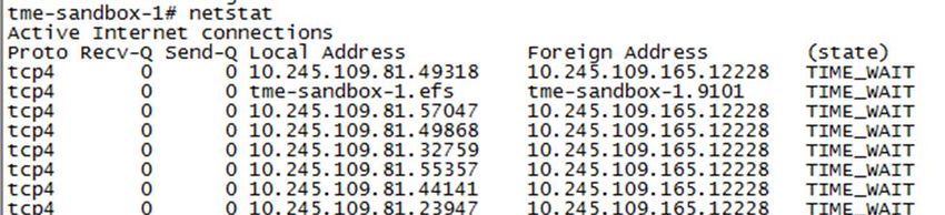
Executive summary

Executive summary
           This document provides design considerations for understanding, configuring, and troubleshooting
           PowerScale Scale-Out NAS external networking. In a Scale-Out NAS environment, the overall network
           architecture must be configured to maximize the user experience. Many factors contribute to overall network
           performance. This document examines network architecture design and best practices including factors such
           as Latency, Flow Control, ICMP, MTU, jumbo frames, congestion, TCP/IP parameters, and IPv6.

Note to readers
           It is important to understand that the network design considerations stated in this document are based on
           general network design and are provided as guidance to PowerScale administrators. As these are
           considerations, all of these may not apply to each workload. It is important to understand each consideration
           and confirm if it pertains to a specific environment.

           Each network is unique, not only from a design perspective but also from a requirements and workloads
           perspective. Before making any changes based on the guidance in this document, it is important to discuss
           modifications with the Network Engineering team. Additionally, as a customary requirement for any major IT
           implementation, changes should first be tested in a lab environment that closely mimics the workloads of the
           live network.

8      Dell EMC PowerScale: Network Design Considerations | H16463.20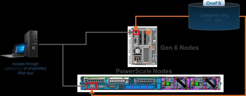
Network architecture design

1          Network architecture design
           The architecture design is the core foundation of a reliable and highly available network, considering capacity
           and bandwidth. Layered on top of the basic foundation are the many applications running on a campus
           network with each requiring specific features and considerations.

           For the following sections, it is important to understand the differences between distribution and access
           switches. Typically, distribution switches perform L2/L3 connectivity while access switches are strictly L2.
           Figure 1 provides the representation for each.

                       Distribution and Access Switches

1.1        General network architecture considerations
           Designing a network is unique to the requirements of each enterprise data center. There is certainly not a
           “one size fits all” design and not a single “good network design.” When approaching network design, it is
           important to use principles as a leading factor, coupled with the enterprise requirements. The requirements
           must include current and future application consumption, providing the guiding factor in major decisions.
           Network design is based on many concepts; the following are considerations and principles to guide the
           process:

               •   Single Points of Failure: Ensure the network design has layers of redundancy. Dependence on a
                   single device or link relates to a loss of resources or outages. The enterprise requirements consider
                   risk and budget, guiding the level of redundancy. Redundancy should be implemented through
                   backup paths and load sharing. If a primary link fails, traffic uses a backup path. Load sharing creates
                   two or more paths to the same endpoint and shares the network load. When designing access to
                   PowerScale nodes, it is important to assume links and hardware will fail, ensuring access to the
                   nodes survives those failures.
               •   Application and Protocol Traffic: Understanding the application data flow from clients to the
                   PowerScale cluster across the network allows for resources to be allocated accordingly while
                   minimizing latency and hops along this flow.
               •   Available Bandwidth: As traffic traverses the different layers of the network, the available bandwidth
                   should not be significantly different. Compare this available bandwidth with the workflow
                   requirements.
               •   Minimizing Latency: Ensuring latency is minimal from the client endpoints to the PowerScale nodes
                   maximizes performance and efficiency. Several steps can be taken to minimize latency, but latency
                   should be considered throughout network design.
               •   Prune VLANs: It is important to limit VLANs to areas where they are applicable. Pruning unneeded
                   VLANs is also good practice. If unneeded VLANs are trunked further down the network, this imposes
                   additional strain on endpoints and switches. Broadcasts are propagated across the VLAN and impact
                   clients.

9      Dell EMC PowerScale: Network Design Considerations | H16463.20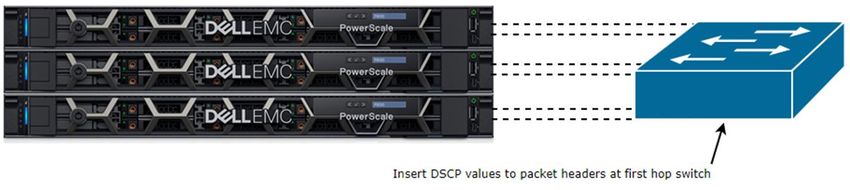
Network architecture design

               •   VLAN Hopping: VLAN hopping has two methods, switch spoofing and double tagging. Switch
                   spoofing is when a host imitates the behavior of a trunking switch, allowing access to other VLANs.
                   Double tagging is a method where each packet contains two VLAN tags, with the assigned or correct
                   VLAN tag is empty and the second as the VLAN where access is not permitted. It is recommended to
                   assign the native VLAN to an ID that is not in use. Otherwise tag the native VLAN to avoid VLAN
                   hopping, allowing a device to access a VLAN it normally would not have access. Additionally, only
                   allow trunk ports between trusted devices and assign access VLANs on ports that are different from
                   the default VLAN.

1.2        Triangle looped topology
           This section provides best practices for Layer 2 Access network design. Although many network architectures
           may meet enterprise requirements, this document takes a closer look at what is commonly referred to as the
           Triangle Looped Access Topology, which is the most widely implemented architecture in enterprise data
           centers.

                       Triangle Looped Access Topology

           The Looped Design Model extends VLANs between the aggregation switches, thus creating the looped
           topology. To prevent actual loops, Spanning Tree is implemented, using Rapid PVST+ or MST. For each
           path, a redundant path also exists, which is blocking until the primary path is not available. Access layer
           uplinks may be used to load balance VLANs. A key point to consider with the Looped Access Topology is the
           utilization of the inter-switch link between the Distribution switches. The utilization must be monitored closely
           as this is used to reach active services.

           The Looped Triangle Access Topology supports VLAN extension and L2 adjacency across the Access layer.
           Through the use of STP and dual homing, the Looped Triangle is extremely resilient. Stateful services are
           supported at the aggregation layer and quick convergence with 802.1W/S.

           Utilizing the Triangle Looped Topology allows for multiple Access Switches to interface with the external
           network of the PowerScale Scale-Out NAS environment. Each PowerScale node within a cluster is part of a
           distributed architecture which allows each node to have similar properties regarding data availability and
           management.

10     Dell EMC PowerScale: Network Design Considerations | H16463.20
Network architecture design
1.3 Link aggregation
In the context of the IEEE 802.1AX standard, link aggregation provides methods to combine multiple Ethernet
interfaces, forming a single link layer interface, specific to a switch or server. Therefore, link aggregation is
implemented between a single switch and a PowerScale node, not across PowerScale nodes.
Implementing link aggregation is neither mandatory nor is it necessary, rather it is based on workload
requirements and is recommended if a transparent failover or switch port redundancy is required.
Link aggregation assumes all links are full duplex, point to point, and at the same data rate, providing graceful
recovery from link failures. If a link fails, traffic is automatically sent to the next available link without
disruption.
It is imperative to understand that link aggregation is not a substitute for a higher bandwidth link. Although link
aggregation combines multiple interfaces, applying it to multiply bandwidth by the number of interfaces for a
single session is incorrect. Link aggregation distributes traffic across links. However, a single session only
utilizes a single physical link to ensure packets are delivered in order without duplication of frames.
As part of the IEEE 802.1AX standard, the Frame Distributor does not specify a distribution algorithm across
aggregated links but enforces that frames must be sent in order without duplication. Frame order is
maintained by ensuring that all frames of a given session are transmitted on a single link in the order that they
are generated by the client. The mandate does not allow for additions or modifications to the MAC frame,
buffering, or processing to re-order frames by the Frame Distributor or Collector.
Thus, the bandwidth for a single client is not increased, but the aggregate bandwidth of all clients increases in
an active/active configuration. The aggregate bandwidth is realized when carrying multiple simultaneous
sessions and may not provide a linear multiple of each link’s data rate, as each individual session utilizes a
single link.
Another factor to consider is depending on the workload, certain protocols may or may not benefit from link
aggregation. Stateful protocols, such as NFSv4 and SMBv2 benefit from link aggregation as a failover
mechanism. On the contrary, SMBv3 Multichannel automatically detects multiple links, utilizing each for
maximum throughput and link resilience.
Link Aggregation
Link Aggregation Advantages Link Aggregation Limitations
Higher aggregate bandwidth for multiple sessions. A Provides resiliency for interface and cabling failures,
single session is confined to a single link. but not for switch failures.
Link resiliency Bandwidth for a single session is not improved as a
single link is used for each session.
Ease of management with a single IP address Depending on the workload, each protocol has
varying limitations and advantages of Link
Load balancing Aggregation
OneFS supports round-robin, failover, load-balance, and LACP link aggregation methods. In previous
releases, FEC was also listed as an option. However, FEC was simply the naming convention for load-
balance. In OneFS 8.2, load-balance replaces the FEC option.
11 Dell EMC PowerScale: Network Design Considerations | H16463.20Network architecture design
1.3.1 Multi-chassis link aggregation
As discussed in the previous section, the IEEE 802.1AX standard does not define Link Aggregation between
multiple switches and a PowerScale node. However, many vendors provide this functionality through
proprietary features. Multiple switches are connected with an Inter-Switch link or other proprietary cable and
communicate via a proprietary protocol forming a virtual switch. A virtual switch is perceived as a single
switch to a PowerScale node, with links terminating on a single switch. The ability to have link aggregation
split with multiple chassis provides network redundancy if a single chassis were to fail.
Each vendor has a proprietary implementation of Multi-Chassis Link Aggregation, but externally the virtual
switch created is compliant with the IEEE 802.1AX standard.
It is important to recognize that regarding bandwidth, the concepts discussed for single switch Link
Aggregation still apply to Multi-Chassis Link Aggregation. Additionally, as the multiple switches form a single
virtual switch, it is important to understand what happens if the switch hosting the control plane fails. Those
effects vary by the vendor’s implementation but will impact the network redundancy gained through Multi-
Chassis Link Aggregation.
12 Dell EMC PowerScale: Network Design Considerations | H16463.20Latency, bandwidth, and throughput
2 Latency, bandwidth, and throughput
Maximizing overall network performance is dependent on several factors. However, the three biggest factors
contributing to end-to-end performance are latency, throughput, and bandwidth. This section focuses on these
factors to maximize the PowerScale user experience.
2.1 Latency
Latency in a packet-switched network is defined as the time from when a source endpoint sends a packet to
when it is received by the destination endpoint. Round trip latency, sometimes referred to as round-trip delay,
is the amount of time for a packet to be sent from the source endpoint to the destination endpoint and
returned from the destination to the source endpoint.
Minimal latency in any transaction is imperative for several reasons. IP endpoints, switches, and routers
operate optimally without network delays. Minimal latency between clients and a PowerScale node ensures
performance is not impacted. As latency increases between two endpoints, this may lead to several issues
that degrade performance heavily, depending on the application.
In order to minimize latency, it is important to measure it accurately between the endpoints. For assessing
PowerScale nodes, this is measured from the clients to a specified node. The measurement could use the IP
of a specific node or the SmartConnect hostname. After configuration changes are applied that impact
latency, it is important to confirm the latency has indeed decreased. When attempting to minimize latency,
consider the following points:
• Hops: Minimizing hops required between endpoints decreases latency. The implication is not to drag
cables across a campus, but the goal is to confirm if any unnecessary hops could be avoided.
Minimizing hops applies at the physical level with the number of switches between the endpoints but
also applies logically to network protocols and algorithms.
• ASICs: When thinking about network hops it also important to consider the ASICs within a switch. If a
packet enters through one ASIC and exits through the other, latency could increase. If at all possible,
it is recommended to keep traffic as part of the same ASIC to minimize latency.
• Network Congestion: NFS v3, NFSv4 and SMB employ the TCP protocol. For reliability and
throughput, TCP uses windowing to adapt to varying network congestion. At peak traffic, congestion
control is triggered, dropping packets, and leading TCP to utilize smaller windows. In turn, throughput
could decrease, and overall latency may increase. Minimizing network congestion ensures it does not
impact latency. It is important to architect networks that are resilient to congestion.
• Routing: Packets that pass through a router may induce additional latency. Depending on the router
configuration, packets are checked for a match against defined rules, in some cases requiring packet
header modification.
• MTU Mismatch: Depending on the MTU size configuration of each hop between two endpoints, an
MTU mismatch may exist. Therefore, packets must be split to conform to upstream links, creating
additional CPU overhead on routers and NICs, creating higher processing times, and leading to
additional latency.
• Firewalls: Firewalls provide protection by filtering through packets against set rules for additional
steps. The filtering process consumes time and could create further latency. Processing times are
heavily dependent upon the number of rules in place. It is good measure to ensure outdated rules are
removed to minimize processing times.
13 Dell EMC PowerScale: Network Design Considerations | H16463.20Latency, bandwidth, and throughput
2.2 Bandwidth and throughput
Understanding the difference between throughput and bandwidth are important for network troubleshooting.
Although these terms are conflated at times, they are actually both unique. Bandwidth is the theoretical
maximum speed a specific medium can deliver if all factors are perfect without any form of interference.
Throughput is the actual speed realized in a real-world scenario, given interference and other environmental
factors such as configuration, contention, and congestion.
The difference between these terms is important when troubleshooting. If a PowerScale node supports 40
GbE, it does not necessarily mean the throughput is 40 Gb/s. The actual throughput between a client and a
PowerScale node is dependent on all of the factors between the two endpoints and may be measured with a
variety of tools.
During the design phase of a data center network, it is important to ensure bandwidth is available throughout
the hierarchy, eliminating bottlenecks and ensuring consistent bandwidth. The bandwidth from the Access
Switches to the PowerScale nodes should be a ratio of what is available back to the distribution and core
switches. For example, if a PowerScale cluster of 12 nodes has all 40 GbE connectivity to access switches,
the link from the core to distribution to access should be able to handle the throughput from the access
switches. Ideally, the link from the core to distribution to access should support roughly a bandwidth of 480
Gb (12 nodes * 40 GbE).
2.2.1 Bandwidth delay product
Bandwidth Delay Product (BDP) is calculated to find the amount of data a network link is capable of, in bytes,
which can be transmitted on a network link at a given time. The keyword is transmitted, meaning the data is
not yet acknowledged. BDP takes into consideration the bandwidth of the data link and the latency on that
link, in terms of a round-trip delay.
The amount of data that can be transmitted across a link is vital to understanding Transmission Control
Protocol (TCP) performance. Achieving maximum TCP throughput requires that data must be sent in
quantities large enough before waiting for a confirmation message from the receiver, which acknowledges the
successful receipt of data. The successful receipt of the data is part of the TCP connection flow. The diagram
below explains the steps of a TCP connection and where BDP is applicable:
14 Dell EMC PowerScale: Network Design Considerations | H16463.20Latency, bandwidth, and throughput
Transmission Control Protocol Message Flow
In the diagram above, four states are highlighted during a TCP connection. The following summarizes each
state:
1. TCP Handshake – Establishes the TCP connection through an SYN, SYN/ACK, ACK
2. Data transmitted to the server. BDP is the maximum amount of data that can be sent at this step.
3. Data acknowledged by Server
4. TCP Connection Close Sequence – Socket closure is initiated by either side
Once the BDP rate is calculated, the TCP stack is tuned for the maximum throughput, which is discussed in
the next section. The BDP is calculated by multiplying the bandwidth of the network link (bits/second) by the
round-trip time (seconds).
For example, a link with a bandwidth of 1 Gigabit per second and a 1 millisecond round trip time, would be
calculated as:
Bandwidth * RTT = 1 Gigabit per second * 1 millisecond =
1,000,000,000 bits per second * 0.001 seconds = 1,000,000 bits = 0.125 MB
Thus, 0.125 MB may be sent per TCP message to the server.
2.3 PowerScale network stack tuning
Once the BDP is calculated and understood, these findings can be applied to modifying the TCP stack on the
PowerScale cluster. All PowerScale clusters do not require TCP stack tuning. Only alter the TCP stack for a
needed workflow improvement. The majority of PowerScale environments do not need TCP tuning. Before
applying any TCP changes, ensure the network is clean and reliable by performing basic checks for
excessive retransmits, duplicate or fragmented packets, and broken pipes.
15 Dell EMC PowerScale: Network Design Considerations | H16463.20Latency, bandwidth, and throughput
PowerScale OneFS is built on FreeBSD. A PowerScale cluster is composed of nodes with a distributed
architecture, and each node provides external network connectivity. Adapting the TCP stack to bandwidth,
latency, and MTU requires tuning to ensure the cluster provides optimal throughput.
In the previous section, BDP was explained in depth and how it is the amount of data that can be sent across
a single TCP message flow. Although the link supports the BDP that is calculated, the OneFS system buffer
must be able to hold the full BDP. Otherwise, TCP transmission failures may occur. If the buffer does not
accept all of the data of a single BDP, the acknowledgment is not sent, creating a delay, and the workload
performance is degraded.
The OneFS network stack must be tuned to ensure on inbound, the full BDP is accepted, and on outbound, it
must be retained for a possible retransmission. Prior to modifying the TCP stack, it is important to measure
the current I/O performance and then again after implementing changes. As discussed earlier in this
document, the tuning below is only guidance and should be tested in a lab environment before modifying a
production network.
The spreadsheet below provides the necessary TCP stack changes based on the bandwidth, latency, and
MTU. The changes below must be implemented in the order below and all together on all nodes. Modifying
only some variables could lead to unknown results. After making changes, it is important to measure
performance again.
Note: The snippet below is only for representation. It is imperative to input the calculated bandwidth, latency,
and MTU specific to each environment.
PowerScale TCP network stack tuning
Download the PowerScale Network Stack Tuning spreadsheet at the following link:
https://dellemc.com/resources/en-us/asset/technical-guides-support-information/h164888-isilon-onefs-
network-stack-tuning.xlsm
16 Dell EMC PowerScale: Network Design Considerations | H16463.20Ethernet flow control
3 Ethernet flow control
Under certain conditions, packets sent from the source to the destination can overwhelm the destination
endpoint. The destination is not able to process all packets at the rate that they are sent, leading to
retransmits or dropped packets. Most scenarios have a fast source endpoint and a slower destination
endpoint; this could be due to processing power or several source endpoints interacting with a single
destination. Flow control is implemented to manage the rate of data transfer between these IP endpoints,
providing an option for the destination to control the data rate, and ensuring the destination is capable of
processing all of the packets from the source.
The IEEEs 802.3x standard defines an Ethernet Flow Control mechanism at the data link layer. It specifies a
pause flow control mechanism through MAC Control frames in full-duplex link segments. For flow control to
be successfully implemented, it must be configured throughout the network hops that the source and
destination endpoints communicate through. Otherwise, the pause flow control frames are not recognized and
are dropped.
By default, PowerScale OneFS listens for pause frames but does not transmit them, meaning it is only
applicable when a PowerScale node is the source. In the default behavior, OneFS recognizes pause frames
from the destination. However, pause frames may be enabled for transmit, depending on the NIC.
Most network devices today do not send pause frames, but certain devices still send them.
3.1 Checking for pause frames
If the network or cluster performance does not seem optimal, it is easy to check for pause frames on a
PowerScale cluster.
If pause frames are reported, it is important to discuss these findings with the network engineering team
before making any changes. As mentioned above, changes must be implemented across the network,
ensuring all devices recognize a pause frame. Contact the switch manufacturer’s support teams or account
representative for specific steps and caveats for implementing flow control before proceeding.
17 Dell EMC PowerScale: Network Design Considerations | H16463.20Ethernet flow control
3.1.1 4th and 5th generation Isilon nodes
On a 4th or 5th generation Isilon cluster, check for pause frames received by executing the following command
from the shell:
isi_for_array -a sysctl dev | grep pause
Check for any values greater than zero. In the example, below, the cluster has not received any pause
frames. If values greater than zero are printed consistently, flow control should be considered.
Checking for pause frames
3.1.2 6th generation Isilon nodes
For 6th generation Isilon nodes with ix NICs, check for pause frames with the following commands:
infPerf-1# sysctl -d dev.ix.0.mac_stats.xon_txd
dev.ix.0.mac_stats.xon_txd: Link XON TransmittedSyncIQ considerations
4 SyncIQ considerations
PowerScale SyncIQ provides asynchronous data replication for disaster recovery and business continuance,
allowing failover and failback between clusters. It is configurable for either complete cluster replication or only
for specific directories. Within a PowerScale cluster, all nodes can participate in replication. After an initial
SyncIQ replication, only changed data blocks are copied minimizing network bandwidth and resource
utilization on clusters.
This section provides considerations for SyncIQ pertaining to external network connectivity. For more
information on SyncIQ, refer to the PowerScale SyncIQ: Architecture, Configuration, and Considerations
white paper.
4.1 SyncIQ disaster recovery with SmartConnect
This section describes best practices for disaster recovery planning with OneFS SmartConnect.
Dedicated static SmartConnect zones are required for SyncIQ replication traffic. As with any static
SmartConnect zone, the dedicated replication zone requires one IP address for each active logical interface.
For example, in the case of two active physical interfaces, 10gige-1 and 10gige-2, requiring two IP addresses.
However, if these are combined with link aggregation, interface 10gige-agg-1 only requires one IP address.
Source-restrict all SyncIQ jobs to use the dedicated static SmartConnect zone on the source cluster and
repeat the same on the target cluster.
By restricting SyncIQ replication jobs to a dedicated static SmartConnect Zone, replication traffic may be
assigned to specific nodes, reducing the impact of SyncIQ jobs on user or client I/O. The replication traffic is
directed without reconfiguring or modifying the interfaces participating in the SmartConnect zone.
For example, consider a data ingest cluster for a sports television network. The cluster must ingest large
amounts of data recorded in 4K video format. The data must be active immediately, and the cluster must
store the data for extended periods of time. The sports television network administrators want to keep data
ingestion and data archiving separate, to maximize performance. The sports television network purchased
two types of nodes: H500s for ingesting data, and A200s for the long-term archive. Due to the extensive size
of the data set, SyncIQ jobs replicating the data to the disaster recovery site, have a significant amount of
work to do on each pass. The front-end interfaces are saturated on the H500 nodes for either ingesting data
or performing immediate data retrieval. The CPUs of those nodes must not be effected by the SyncIQ jobs.
By using a separate static SmartConnect pool, the network administrators can force all SyncIQ traffic to leave
only the A200 nodes and provide maximum throughput on the H500 nodes.
4.2 Replication traffic over dedicated WAN links
Depending on the network topology and configuration, in certain cases PowerScale SyncIQ data may be sent
across a dedicated WAN link separated from client traffic. Under these circumstances, the recommended
option is utilizing a different subnet on the PowerScale cluster for replication traffic, separated from the subnet
for user data access.
19 Dell EMC PowerScale: Network Design Considerations | H16463.20Quality of Service (QoS)
5 Quality of Service (QoS)
As more applications compete for a shared link with limited throughput, ensuring Quality of Service (QoS) for
application success is critical. Each application has varying QoS requirements to deliver not only service
availability, but also an optimal client experience. Associating each application to an appropriate QoS
marking, provides traffic policing, allowing packets to be prioritized as required across a shared medium, all
while delivering an ideal client experience.
QoS may be implemented through different methods. However, the most common is through a Differentiated
Services Code Point (DSCP), specifying a value in the packet header that maps to an effort level for traffic.
PowerScale OneFS does not provide an option for tagging packets with a specified DSCP marking. As a best
practice, configure the first hop ports on switches connected to PowerScale nodes to insert DSCP values. It is
important to note that OneFS does retain headers for packets that already have a specified DSCP value.
QoS and OneFS – Inserting DSCP values
20 Dell EMC PowerScale: Network Design Considerations | H16463.20Software-Defined Networking
6 Software-Defined Networking
Software-Defined Networking (SDN) provides automated policy-based management of network architecture.
The management and administration are centralized by separating the control and data planes. SDN
architectures include a controller functioning as a central point of management and automation. The controller
is responsible for relaying information downstream to firewalls, routers, switches, and access points. On the
contrary, the controller sends information upstream to applications and orchestration frameworks, all while
presenting the SDN architecture as a single device.
Datacenters that have an SDN architecture and a PowerScale cluster must have traditional access switches
connected to PowerScale nodes, presenting a traditional network architecture to OneFS.
PowerScale and Software-Defined Networking
The SDN implementation of each vendor is unique and it is critical to understanding the scalability and
limitations of a specific architecture. Some of the SDN implementations are based on open standards like
OpenFlow, while other vendors use a mix of proprietary and open standards, and others use a completely
proprietary implementation. Reviewing the limits of a specific implementation is essential to understanding
how to maximize performance. If a PowerScale cluster is configured for use with SDN through a traditional
access switch, consider the following:
• OneFS does not support VRFs and VXLANs. An intermediary solution is required for implementing
VLAN to VXLAN mapping.
• Understand the control plane scalability of each SDN implementation and if it would impact OneFS.
• The MTU implementation for each vendor varies. Ensure consistent MTUs across all network hops.
• Each switch vendor provides a different set of SDN capabilities. Mapping differences is key to
developing a data center architecture to include a PowerScale cluster while maximizing network
performance.
• Not only is each vendor's capability unique when it comes to SDN. But, the scalability of each solution
and cost varies significantly. The intersection of scalability and cost determines the architecture limits.
• As each SDN implementation varies, consider the impacts on the automation and policy-driven
configuration, as this is one of the significant advantages of SDN. Additionally, consider the
automation interactions with Isilon PAPI.
21 Dell EMC PowerScale: Network Design Considerations | H16463.20PowerScale OneFS ports
7 PowerScale OneFS ports
PowerScale OneFS uses a number of TCP and UDP ports, which are documented in the Security
Configuration Guide available at the following link: https://community.emc.com/docs/DOC-57599
22 Dell EMC PowerScale: Network Design Considerations | H16463.20SmartConnect considerations
8 SmartConnect considerations
This section provides considerations for using the PowerScale SmartConnect load-balancing service. The
general IP routing principles are the same with or without SmartConnect.
SmartConnect acts as a DNS delegation server to return IP addresses for SmartConnect zones, generally for
load-balancing connections to the cluster. The IP traffic involved is a four-way transaction shown in Figure 8.
SmartConnect DNS delegation steps
In Figure 8, the arrows indicate the following steps:
1. Blue arrow (step 1): The client makes a DNS request for sc-zone.domain.com by sending a DNS
request packet to the site DNS server.
2. Green arrow (step 2): The site DNS server has a delegation record for sc-zone.domain.com and
sends a DNS request to the defined nameserver address in the delegation record, the SmartConnect
service (SmartConnect Service IP Address).
3. Orange arrow (step 3): The cluster node hosting the SmartConnect Service IP (SSIP) for this zone
receives the request, calculates the IP address to assign based on the configured connection policy
for the pool in question (such as round robin), and sends a DNS response packet to the site DNS
server.
4. Red arrow (step 4): The site DNS server sends the response back to the client.
8.1 SmartConnect network hierarchy
As SmartConnect subnets and pools are defined it is important to understand the SmartConnect hierarchy, as
displayed in the following figure:
SmartConnect network hierarchy – OneFS releases prior to 8.2
Throughout the network design phase, for releases prior to OneFS 8.2, consider that a single SSIP is defined
per subnet. However, under each subnet, pools are defined, and each pool will have a unique SmartConnect
Zone Name. It is important to recognize that multiple pools lead to multiple SmartConnect Zones utilizing a
23 Dell EMC PowerScale: Network Design Considerations | H16463.20SmartConnect considerations
single SSIP. As shown in the diagram above, a DNS provider is defined per Groupnet, which is a feature in
OneFS 8.0 and newer releases. In releases before 8.0, a DNS per Groupnet was not supported.
OneFS 8.2 introduces support for multiple SSIPs per subnet, as displayed in the following figure:
SmartConnect network hierarchy – OneFS release 8.2
For more information on SmartConnect multi-SSIP, refer to Section 8.14, SmartConnect Multi-SSIP.
8.2 Load balancing
SmartConnect load balances incoming network connections across SmartConnect Zones composed of
nodes, network interfaces, and pools. The load balancing policies are Round Robin, Connection Count, CPU
Utilization, and Network Throughput. The most common load balancing policies are Round Robin and
Connection Count, but this may not apply to all workloads. It is important to understand whether the front-end
connections are being evenly distributed, either in count or by bandwidth. Front-end connection distribution
may be monitored with InsightIQ or the WebUI. It is important to understand how each Load Balancing Policy
functions and testing it in a lab environment prior to a production roll-out, as each workload is unique. The
table below lists suggested policies based on the workflow, but these are general suggestions, and may not
always be applicable.
Generally speaking, starting with Round Robin is recommended for a new implementation or if the workload is
not clearly defined. As the workload is further defined and based on the Round Robin experience, another
policy can be tested in a lab environment.
Suggested SmartConnect load balancing policies
Workload
Load General Few Clients with Many Persistent NFS Many Transitory NFS Automounts
Balancing or Other Extensive & SMB Connections Connections or UNC Paths
Policy Usage (HTTP, FTP)
Round Robin ✓ ✓ ✓ ✓ ✓
24 Dell EMC PowerScale: Network Design Considerations | H16463.20You can also read