SCIENTIFIC WORKFLOWS APPLIED TO THE COUPLING OF A CONTINUUM (ELMER V8.3) AND A DISCRETE ELEMENT (HIDEM V1.0) ICE DYNAMIC MODEL
←
→
Page content transcription
If your browser does not render page correctly, please read the page content below
Geosci. Model Dev., 12, 3001–3015, 2019
https://doi.org/10.5194/gmd-12-3001-2019
© Author(s) 2019. This work is distributed under
the Creative Commons Attribution 4.0 License.

Scientific workflows applied to the coupling of a
continuum (Elmer v8.3) and a discrete element
(HiDEM v1.0) ice dynamic model
Shahbaz Memon1,2 , Dorothée Vallot3 , Thomas Zwinger4 , Jan Åström4 , Helmut Neukirchen2 , Morris Riedel1,2 , and
Matthias Book2
1 JülichSupercomputing Centre, Forschungszentrum Jülich, Leo-Brandt Straße, 52428 Jülich, Germany
2 Facultyof Industrial Engineering, Mechanical Engineering and Computer Science, University of Iceland, Reykjavik, Iceland
3 Department of Earth Sciences, Uppsala University, Uppsala, Sweden
4 CSC – IT Center for Science Ltd., Espoo, Finland

Correspondence: Shahbaz Memon (m.memon@fz-juelich.de)

Received: 25 June 2018 – Discussion started: 20 July 2018
Revised: 22 May 2019 – Accepted: 24 May 2019 – Published: 15 July 2019

Abstract. Scientific computing applications involving com-      workflow management system, the composition, manage-
plex simulations and data-intensive processing are often        ment, and execution of the glacier modelling workflow be-
composed of multiple tasks forming a workflow of comput-        comes easier with respect to usage, monitoring, maintenance,
ing jobs. Scientific communities running such applications      reusability, portability, and reproducibility in different envi-
on computing resources often find it cumbersome to man-         ronments and by different user groups. Last but not least, the
age and monitor the execution of these tasks and their as-      workflow helps to speed the runs up by reducing model cou-
sociated data. These workflow implementations usually add       pling I/O overhead and it optimizes CPU utilization by avoid-
overhead by introducing unnecessary input/output (I/O) for      ing idle CPU cores and running the models in a distributed
coupling the models and can lead to sub-optimal CPU utiliza-    way on the HPC cluster that best fits the characteristics of
tion. Furthermore, running these workflow implementations       each model.
in different environments requires significant adaptation ef-
forts, which can hinder the reproducibility of the underlying
science. High-level scientific workflow management systems
(WMS) can be used to automate and simplify complex task
structures by providing tooling for the composition and ex-     1   Introduction
ecution of workflows – even across distributed and hetero-
geneous computing environments. The WMS approach al-            The complexity of glaciological systems is increasingly re-
lows users to focus on the underlying high-level workflow       flected by the physical models used to describe the pro-
and avoid low-level pitfalls that would lead to non-optimal     cesses acting on different temporal and spatial scales. Ad-
resource usage while still allowing the workflow to remain      dressing these complexities inevitably involves the combi-
portable between different computing environments. As a         nation of different sub-models into a single simulation that
case study, we apply the UNICORE workflow management            encompasses multiple tasks executed in a distributed com-
system to enable the coupling of a glacier flow model and       puting facility. A particularly good example of such a com-
calving model which contain many tasks and dependencies,        bination is the simulation of calving behaviour at the front
ranging from pre-processing and data management to repet-       of glaciers that combines continuum model and discrete ele-
itive executions in heterogeneous high-performance com-         ment model simulations. These computational tasks are con-
puting (HPC) resource environments. Using the UNICORE           nected to each other to form a “scientific workflow”: the
                                                                composition and execution of multiple data processing steps

Published by Copernicus Publications on behalf of the European Geosciences Union.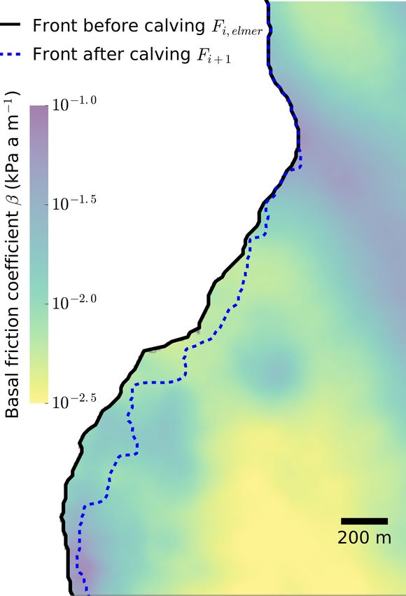
3002                                                  S. Memon et al.: Scientific workflows applied to glacier model coupling

as defined by the requirements of the scientific application        2     State of the art
concerned.
   Carrying out the discrete calving and ice flow modelling         2.1    Modelling and simulating the calving of a glacier
dynamically and as one workflow instance becomes very la-
borious without an automated mechanism. The analysis of             The calving behaviour at the front of glaciers is still a largely
such a workflow in more detail reveals that there are even          unresolved topic in modern theoretical glaciology. The core
more steps than just the two model elements mentioned               of the problem is that ice as a material shows different be-
above. These include, for instance, pre- and post-processing,       haviour, depending on the timescale on which the forces
job dependency management, job submission, monitoring,              are applied (Greve and Blatter, 2009). The everyday expe-
conditional invocations, and multi-site data management.            rience is that ice is a brittle solid body (e.g. breaking ici-
These steps can be cumbersome for a user; for example, if           cles). Such behaviour is observed if the reaction to a force
any step produces an unexpected output, which can cause the         is in the range of seconds to minutes. However, theoretical
whole workflow to fail, this may require the user to re-run the     glaciology in recent years has rather dealt with the long-term
whole workflow. These issues often indicate that workflow           (i.e. beyond minutes to millennia) behaviour of glaciers and
implementation is sub-optimal as it requires coupling over-         ice sheets, where ice shows the property of a strong non-
head (such as unnecessary I/O), or because a high number            linear, shear thinning fluid (Greve and Blatter, 2009). This
of CPU cores is allocated; this suits the most CPU-intensive        leads to a description of long-term ice flow dynamics in clas-
task to be executed, but leaves cores idle when other tasks are     sical ice sheet and glacier dynamics models (e.g. Gagliardini
executed that are less CPU-intensive or do not scale well. A        et al., 2013) in terms of thermo-mechanically coupled non-
workflow management system (WMS) allows the user to au-             Newtonian Stokes flow continuum models.
tomate and ease the workflow management steps by means                 In stark contrast to such a description, the process of crack-
of abstraction, which not only increases usability, but also        ing or calving (i.e. the complete failure of ice fronts) is an in-
enhances portability to different computing platforms and,          herently discontinuous process, that – if addressed in a phys-
in turn, reproducibility of the scientific model runs. In our       ically correct way – requires a completely different model
case, it also allowed us to focus on performance aspects, thus      approach. Models adopting a discontinuous approach have
enabling a reduction in coupling I/O overhead and an opti-          been developed in recent years (e.g. Åström et al., 2013;
mization of the CPU utilization.                                    Åström et al., 2014; Bassis and Jacobs, 2013). These models
   The main contribution of this article is to identify the         describe the glacier as discrete particles connected by elas-
workflow problems that need to be solved with respect to            tic beams that can be dissolved if a certain critical strain
coupling a glacier continuum model and a discrete element           is exceeded, and are therefore able to mimic the elastic as
model in an optimized way, in order to elicit corresponding         well as the brittle behaviour of ice. The size of these model
requirements that address – among others – portability, per-        particles (in the range of metres), which need to resolve
formance improvements, and CPU utilization, and to imple-           a whole glacier of several cubic kilometres, inherently de-
ment an automated workflow based on the UNICORE (Streit             mands large computational resources. In addition, the char-
et al., 2010) distributed computing middleware, in particular       acteristic speeds of advancing cracks is close to the speed of
using the UNICORE workflow management system (Memon                 sound, which, in combination with the small spatial resolu-
et al., 2007). We demonstrate this by combining ice flow            tion, imposes a maximum allowed time-step size of a fraction
modelling and discrete calving into a high-level easy-to-use        of a second.
and performance-optimized scientific workflow.                         In other words, the combination of a discrete element and
   This article is structured as follows: Sect. 2 provides a dis-   a continuum ice flow model is a temporal multi-scale prob-
cussion on the state of the art in glacier calving modelling        lem, where the former basically describes an instant change
and on scientific workflows. The targeted glacier modelling         of geometry or rheology for the latter. This means that both
case study is presented in Sect. 3.1, which describes a work-       models need to be run in a sequential manner, with several
flow baseline used for model coupling and the applications          repetitions. This defines a workflow of two model compo-
used for execution. Next, the creation of a good solution is        nents that strongly differ in computational demand. In ad-
demonstrated, by first identifying the requirements to solve        dition, these two model components have to effectively and
these problems (Sect. 4.1), followed by the creation of an          efficiently exchange data – namely, the new geometries ei-
improved matching workflow design (Sect. 4.2), and finally          ther changed by flow deformation or by calving as well as
the implementation of the workflow (Sect. 4.3). The imple-          damage caused by fracturing.
mented workflow is evaluated in Sect. 5 from different per-
spectives, including a discussion on how the requirements           2.2    Scientific workflows
from Sect. 4.1 have been fulfilled. Finally, a summary and an
outlook conclude the article.                                       A scientific workflow can be defined as the composition and
                                                                    execution of multiple data processing steps as required by a
                                                                    scientific computing application. Such a workflow captures

Geosci. Model Dev., 12, 3001–3015, 2019                                                www.geosci-model-dev.net/12/3001/2019/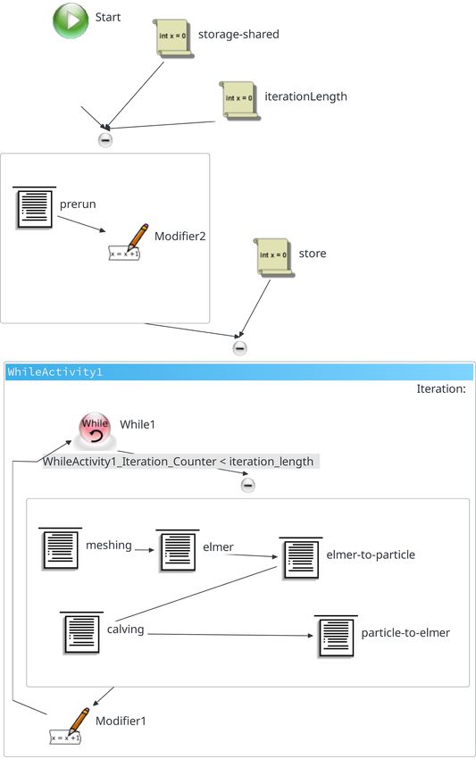
S. Memon et al.: Scientific workflows applied to glacier model coupling                                                       3003

a series of analytical steps of computational experiments to        concerning HPC environments. Hence, it is important to im-
“aid the scientific discovery process through the combination       plement the glacier modelling case study with a WMS that
of scientific data management, analysis, simulation, and vi-        provides a rich graphical front-end and simultaneously offers
sualization” (Barker and van Hemert, 2008). Conceptually,           a generic and seamless execution and monitoring of applica-
scientific workflows can be considered (and are typically vi-       tions on HPC-based infrastructures in particular. Consider-
sualized) as graphs consisting of nodes representing indi-          ing this requirement, the glacier model coupling case study
vidual tasks and constructs, and edges representing different       is automated via our standards-based workflow management
types of associations between nodes, such as sequential or          system (Memon et al., 2007), which is a part of the Uniform
conditional execution.                                              Interface to Computing Resources (UNICORE) (Streit et al.,
   Carrying out the discrete calving and ice flow model             2010) distributed computing middleware. It is specifically
simulations becomes complex as multiple parallel high-              designed to support HPC applications deployed in a mas-
performance computing (HPC) applications are involved, es-          sively parallel environment. As described later in Sect. 4.3,
pecially if there are tasks in the workflow that consist of pre-    our WMS for UNICORE provides a rich graphical interface
and post-processing phases, and require multi-site and iter-        for the composition, management, and monitoring of scien-
ative job and data management functions. The overall sce-           tific workflows by users with different levels of system ex-
nario may easily become unmanageable, and the workflow              pertise.
management might be prone to errors, failures, poor repro-
ducibility, and sub-optimal HPC resource usage.
   A workflow scenario such as this will be even more chal-         3     Case study: Kronebreen glacier simulation
lenging when some parts are launched on heterogeneous re-
                                                                    Coupling a continuum ice flow model and a particle-based
source management systems equipped with different file sys-
                                                                    calving model of the Kronebreen glacier provides a well-
tems, different data transfer mechanisms, and different job
                                                                    suited case study for the application of a WMS. More details
submission systems. In our case, for example, two differ-
                                                                    on the scientific background of such a coupling and on the
ent HPC clusters with different characteristics are simulta-
                                                                    models are presented in Vallot et al. (2018). In Vallot et al.
neously used: one for the ice flow modelling and another one
                                                                    (2018), a series of key processes (ice flow, surface and sub-
for the discrete element (i.e. calving) modelling executions.
                                                                    glacial hydrology, ocean water mixing, undercutting at the
   These workflow challenges can be addressed by a work-
                                                                    front, and finally ice calving in the ocean) were simulated by
flow management system (WMS) that is capable of man-
                                                                    a sequence of different models in a one-way coupling. The
aging the complex dependencies of many job steps with
                                                                    aim was to show the feasibility of the coupling by compar-
multiple conditional and nested constructs. Several scientific
                                                                    ing observations and historical data to simulation results and
WMSs have been developed to automate complex applica-
                                                                    to identify the resulting interactions via this global approach.
tions from multi-disciplinary backgrounds. Ferreira da Silva
                                                                    In this article, we introduce a full coupling that can be used
et al. (2017) comprehensively categorized different workflow
                                                                    for prognostic simulations. To simplify the problem we only
management systems according to the type of execution sce-
                                                                    use two models: an ice flow model (Elmer/Ice) and a dis-
nario and capabilities they offer, and also identified their spe-
                                                                    crete particle model (the Helsinki Discrete Element Model –
cialized scientific domain. One example is Taverna (Wolsten-
                                                                    HiDEM). In the following, we describe the software executa-
croft et al., 2013), which in principle is a general WMS, but is
                                                                    bles and the underlying workflow.
significantly driven by bio-informatics communities with the
need for high-throughput computing (HTC)-driven “-omics”            3.1    Conceptual scheme
analyses (proteomics, transcriptomics, etc.) and thus lacks
the distinct support of cutting-edge HPC systems such as            Kronebreen is a tidewater glacier (ice flows directly into
those used in our case study. In a similar manner, the South-       the ocean) and is one of the fastest-flowing glaciers of the
ern California Earthquake Center (SCEC) Earthworks Portal,          Svalbard archipelago. After a period of stability, Kronebreen
a part of the US infrastructure Extreme Science and Engi-           glacier started to retreat in 2011 and has continued since then.
neering Discovery Environment (XSEDE), adopts two other             This glacier has been extensively studied (e.g. Kääb et al.,
HTC-related workflow management systems, namely Pega-               2005; Luckman et al., 2015; Nuth et al., 2012; van Pelt and
sus (Deelman et al., 2015) and DAGMan (Frey, 2003). Pe-             Kohler, 2015; Schellenberger et al., 2015; Vallot et al., 2017),
gasus itself is just a component on top of DAGMan that, in          partly due to its location (close to a research station) and its
turn, is based on the HTCondor middleware for HTC, which            interesting behaviour in terms of sliding and calving. For this
in our review did not really meet the full capabilities required    reason, it is a good candidate for the present study. The aim
for HPC in general or the particular capabilities needed for        is to reproduce both continuous (ice flow) and discrete (calv-
the large supercomputers used in our study.                         ing) processes using a finite element model (FEM) and a first-
   Our scenario from the domain of glaciology using HPC             principle ice fracture model respectively.
technology includes a complex workflow graph; therefore,
it is not easily manageable for users with limited expertise

www.geosci-model-dev.net/12/3001/2019/                                                Geosci. Model Dev., 12, 3001–3015, 2019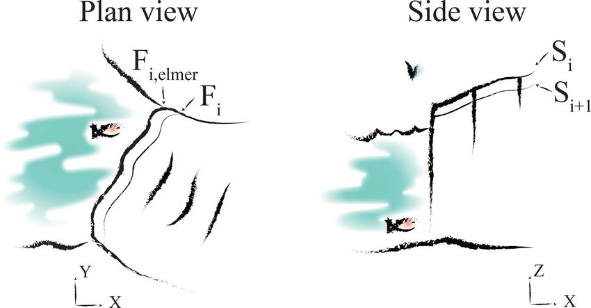
3004 S. Memon et al.: Scientific workflows applied to glacier model coupling
3.2 Applications: meshing tools, continuum, and if a given threshold is exceeded. An additionally ap-
discrete ice dynamics model plied repelling potential based on distance guarantees
a non-intersection of compressed loose particles. Solv-
Within our application, we use the continuum model ing Newton’s equation on such a set-up, it is possi-
Elmer/Ice (Gagliardini et al., 2013), and the discrete calving ble to realistically reproduce the behaviour of fractur-
model HiDEM (Åström et al., 2013). Both codes can be run ing. The downside of this approach is the high compu-
on large parallel HPC platforms. Implied by the physics that tational power demand, as the several cubic kilometre
have to be addressed and by the modelling tools, the work- large glacier is discretized in pieces of a few tens of cu-
flow contains three main applications that are part of the case bic metres. Furthermore, the time-step size for the sim-
study implementation: ulation is imposed by the ratio of the speed of sound
to the typical length of the discretized particles, which
1. Meshing: Gmsh (Geuzaine and Remacle, 2009) is the
clearly falls below seconds. Hence, despite the fact that
applied meshing tool used to provide the updated mesh
the code is utilizing massive parallel computing using
for the continuum ice flow model run. It creates an up-
the MPI paradigm, only a few minutes to hours of phys-
dated footprint mesh in the horizontal plane that is fur-
ical time can be computed, even on a huge HPC cluster.
ther extruded and reshaped using the bedrock as well
HiDEM receives the initial geometry from Elmer/Ice, in
as free surface elevation to form the three-dimensional
the form of gridded data over a limited area at the tongue
computing mesh for the ice dynamic simulation. Gmsh
of the glacier, and also receives the basal friction coef-
is an open source, versatile and scriptable meshing tool
ficient distribution computed within the continuum ice
that perfectly matches the demands of being deployed
flow model.
within a workflow like this one. Gmsh applies a bottom-
up geometry and meshing strategy, starting from outline 3.3 Initial base workflow
points of the glacier, building a closed loop of its out-
line, and further creating a planar surface that is meshed The continuum ice flow model and the discrete calving model
in two dimensions. need to be coupled, which leads to a scientific workflow. A
baseline version of the workflow was initially realized by a
2. Continuum modelling: Elmer/Ice (Gagliardini et al., Bash shell script that calls the above executables as well as
2013) is the open source ice sheet model used for com- additional Python helper code, and performs all of the re-
puting the long-term dynamics of the glacier. Elmer/Ice quired management operations using shell script commands.
is based on the multi-physics package Elmer (Råback The underlying workflow is as follows:
et al., 2018), an open source finite element code devel-
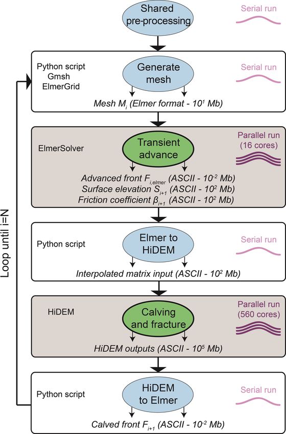
oped by CSC – IT Center for Science Ltd. Elmer/Ice 3.3.1 Step 1: generate the mesh for Elmer/Ice
is able to utilize parallel processing, applying the mes-
sage passing interface (MPI) paradigm (Message Pass- At t = ti , the front position, Fi , and the glacier contour (two-
ing Interface Forum, 2012) that uses messages to ex- dimensional boundaries of the glacier), Cont, are given as
change data between nodes of a distributed parallel input to create the mesh, Mi . This determines the domain of
processing environment, and – for certain solver im- the glacier for the ice flow model Elmer/Ice. A Python script
plementations – OpenMP (Dagum and Menon, 1998) invokes the meshing executable gmsh to build the mesh from
for shared-memory parallel processing using multi- the contour and the front position, and invokes ElmerGrid
threading. Elmer also provides the ElmerGrid exe- to convert it into Elmer format. In this particular application,
cutable that can be used to convert the mesh created by the mesh is then split into 16 partitions. This step runs as a
Gmsh and at the same time perform a domain decom- single-threaded application; with respect to resource require-
position on the footprint, using the METIS library. The ments, mesh generation is not very CPU-intensive (serial, i.e.
solver executable ElmerSolver has a built-in feature 1 CPU core), but it consumes some storage space.
to internally extrude the given footprint mesh into lay-
ered columns of prisms and impose the given surface 3.3.2 Step 2: ice flow modelling and conversion to the
and bedrock elevation to form the volume of the glacier. HiDEM domain
Elmer is built on a shared library concept, meaning
all solver modules are loaded during runtime. This en- The continuum ice flow model is executed using the
ables the easy deployment of user-written functions and ElmerSolver application which is an MPI-based imple-
solvers through an application program interface (API). mentation and part of the Elmer application suite. The num-
ber of time steps (Nt ) depends on the glacier and process
3. Discrete modelling: HiDEM (Helsinki Discrete Ele- studied as well as the spatial resolution. Here, we simulate
ment Model) (Åström et al., 2013) is a discrete ele- Nt = 11 d in one run, which – using a time-step size of 1 d –
ment model that represents the glacier as mass-points corresponds to the update frequency of remote-sensing satel-
connected by massless beams that are allowed to break lite data which were used for model validation.
Geosci. Model Dev., 12, 3001–3015, 2019 www.geosci-model-dev.net/12/3001/2019/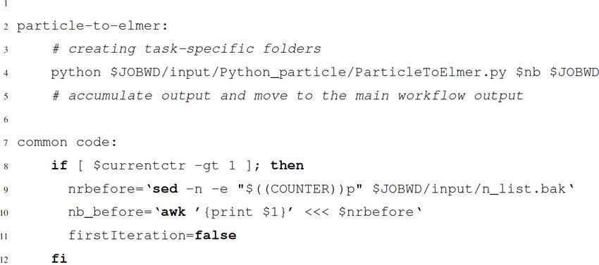
S. Memon et al.: Scientific workflows applied to glacier model coupling                                                          3005

                                                                      3.3.3   Step 3: discrete particle modelling and conversion
                                                                              to the Elmer/Ice domain

                                                                      The converted output from Elmer/Ice is passed to HiDEM.
                                                                      The implementation of HiDEM requires an MPI environment
                                                                      (560 cores running the MPI processes in our case), because in
                                                                      comparison to the other steps, it consumes the biggest share
                                                                      of CPU hours due to the high spatial and temporal resolu-
                                                                      tion. The stress field in both models is a consequence of grav-
Figure 1. Conceptual plan and side view of an Elmer/Ice transient     ity acting on the specific ice geometry and therefore initially
run. The initial front Fi and surface Si are evolved to a new front   identical (differences arise only owing to the discretization
position Fi,elmer and a new surface elevation Si+1 .                  method). Deviations between the models are only in the re-
                                                                      sponse to stress, i.e. the rheology. Elmer/Ice deformations are
                                                                      viscous, HiDEM elastic–brittle. This means that in the lat-
   As the basal boundary condition (BC), we assume a no-              ter only elastic deformations (but no viscous deformations)
penetration condition with no basal melting nor accumula-             are modelled and the transfer of viscous rheology param-
tion and basal friction (currently Weertman friction law). The        eters from Elmer/Ice to HiDEM can be omitted. The frac-
upper BC is defined as a stress-free surface and is able to           ture timescale is determined by the ratio of the glacier’s spa-
evolve during the simulation following an advection equation          tial dimension and the velocity of sound, which is usually in
forced by a surface mass balance. As the BC in contact with           the sub-second range. Ice flow, in comparison, occurs on the
the ocean, the normal component of the stress vector is equal         scale of relaxation time, which is dominated by a large vis-
to the hydrostatic water pressure exerted by the ocean where          cosity in relation to a significant smaller Young’s modulus
ice is below sea level. The front is also able to evolve, using a     and is therefore in the range of hours and beyond – several
Lagrangian scheme (i.e. mesh velocity equal to ice flow ve-           orders of magnitude larger. Consequently, HiDEM results
locity corrected by melting). The temperature profile in the          can be interpreted as instantaneous for the ice flow model,
ice and lateral BC are prescribed but can be changed easily.          Elmer/Ice. Under this assumption, we scale down the friction
The ice flows as a non-linear isotropic viscous fluid follow-         parameters HiDEM receives from Elmer/Ice (in our case us-
ing Glen’s flow law (e.g. Cuffey and Paterson, 2010), and the         ing the factor 10−4 ) so as to increase the sliding speeds and
Stokes equations for an incompressible fluid are solved over          reduce the physical time (in our case 100 s) needed to evalu-
the ice volume. Elmer/Ice executes a solver input file, SIFi ,        ate the resulting fractures in order to avoid excess computa-
with the above-mentioned parameters.                                  tions. Despite the scaling, the relative distribution of friction
   After the simulation, the glacier front has a new position         parameters is maintained. As neither the glacier geometry
Fi,elmer , a new surface elevation Si+1 (see Fig. 1), and a map       nor the value of ice density or gravity are altered, this sim-
of basal friction coefficients (determined by a linear sliding        ply accelerates, but does not significantly alter the general
law). These form the output of Elmer/Ice and the input to Hi-         glacier dynamics; this leads to the same fraction pattern that
DEM. Elmer/Ice can be sped up by parallel processing, but is          would have been obtained with unscaled friction parameters.
not as CPU-intensive as HiDEM; hence, only 16 CPU cores               A new front position, Fi+1 , is determined after the simula-
are used for Kronebreen glacier in this part of the workflow.         tion. In this step, the data produced are rather large because
   The output format of Elmer/Ice does not match the input            of the high spatial resolution.
format of HiDEM, and HiDEM does not need to process                      Once a HiDEM run is completed, the next step is to re-
the whole glacier, only the front that is relevant for calving.       convert this data set to the Elmer/Ice format, so that the next
Hence, a conversion step runs a set of helper scripts (“Elmer         iteration of the coupled glaciology models’ workflow can be-
to HiDEM”) implemented in Python. This step performs a                gin. Again, a Python script (“HiDEM to Elmer”) is used to
conversion of the output of ElmerSolver to the HiDEM                  convert the HiDEM output into a format that can be read by
grid (10 m × 10 m in our case) that is used for the calving           Gmsh and ElmerGrid. For this purpose, the new front posi-
front of the glacier. Elevations are offset so that the mini-         tion Fi+1 (after calving) and surface elevation Si+1 are rein-
mum bed elevation is equal to zero. It also includes places           troduced into Step 1 at t = ti+1 . Again, the conversion is per-
with no ice where the surface elevation is equal to the bed           formed in serial execution. After this step, the workflow reit-
elevation. This conversion step creates a text input file for         erates from Step 1.
HiDEM, Pini , with coordinates, surface, bed and basal fric-
tion coefficients. This conversion is performed on a single
CPU.

www.geosci-model-dev.net/12/3001/2019/                                                  Geosci. Model Dev., 12, 3001–3015, 2019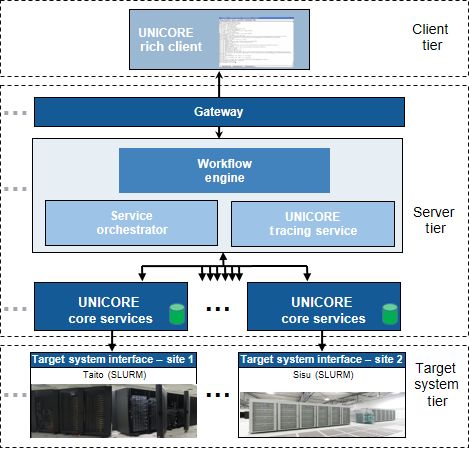
3006                                                  S. Memon et al.: Scientific workflows applied to glacier model coupling

4     Workflow                                                        – R4: minimize coupling I/O
                                                                        The cost of data sharing across the jobs of the work-
4.1    Requirements analysis
                                                                        flow steps becomes high when the data are unneces-
The problem analysis of the initial shell script-based work-            sarily replicated across each of the job steps. This in-
flow led to a set of requirements that aim at improving the             creases the use of storage space and negatively impacts
workflow with respect to usability, adaptability, maintain-             the overall workflow footprint in terms of resource con-
ability, portability, robustness, resource usage (I/O and CPU),         sumption, in particular with respect to I/O performance.
and overall runtime. Based on the weaknesses of the ini-                Therefore, an adequate data sharing mechanism that
tial workflow implementation, we particularly focused on                minimizes the coupling-related I/O of all of the tasks
reducing the overhead associated with the initial coupling              should be available, which concurrently allows a sim-
approach by improving the overall runtime, optimizing the               plified integration of data at application runtime. It will
CPU resource usage, and coupling-related I/O, as well as the            also facilitate optimal storage resource usage (e.g. of a
factors mentioned previously regarding enabling a uniform               parallel file system) in the target system. This is of par-
access to widen the scientific community’s adoption of this             ticular importance when dealing with two different HPC
glaciology workflow.                                                    clusters running different steps of the workflow, where
   The requirements elicitation phase yielded the following             data need to be exchanged between the HPC clusters.
requirements, which led to an improved design and imple-              – R5: minimize CPU resource consumption
mentation of the workflow (a summary of the requirements
                                                                        The continuum ice flow model (Elmer/Ice) is less CPU
and a description of the UNICORE-based implementation
                                                                        resource-intensive than the calving model (HiDEM).
are provided in Table 1):
                                                                        This is due to very different spatial and temporal res-
    – R1: readability and understandability                             olutions but also the models themselves, which require
      The continuous development, maintenance, and dissem-              different amounts of computational resources (16 cores
      ination of a scientific application for collaboration re-         for the continuous ice flow model, and 560 cores for
      quires that the implementation have a clean, clearly              the discrete particle model). Getting access to CPU time
      modularized, and system-independent code. The work-               on a small HPC cluster is typically easier than on big
      flow implementation should not contain static resource-           clusters; hence, the workflow will support the possibil-
      specific details or malformed data locations as they may          ity of running these two significantly different steps on
      lead to subsequent runtime task failures. As our case             two different computing resources, which reduces the
      study consists of many independent applications related           amount of CPU and queuing time needed on the larger
      to each workflow task, it is important that the tasks are         cluster. If the executions are run on heterogeneous clus-
      well-segregated and do not overlap. A well-segregated             ters, a layer of abstraction is needed that encapsulates
      workflow not only helps the application developer to              the intricacies of different resource management sys-
      further enhance the application, but also to distribute the       tems (see R11). If the executions are run on the same
      code in order to collaborate with a larger scientific com-        cluster, the allocation of more cores than are actually
      munity.                                                           used needs to be avoided (e.g. do not allocate 560 cores
                                                                        to run a 16-core Elmer/Ice job or even to execute a serial
    – R2: sequential pipeline                                           data conversion script).
      The execution of jobs in the workflow should be or-
      chestrated in a sequential manner such that one job step        – R6: parametric execution
      should not commence unless all previous steps have                In our case study, most of the job steps need to be exe-
      been completed. This requirement envisages the whole              cuted in an iterative way. With every new iteration, input
      scenario as a sequence of jobs that should connect all the        has to be extracted from a plain ASCII text file, called
      scientific applications taking part in the glacier model          n_list.txt, which contains the surface velocity data
      coupling case study.                                              of some days of ice flow simulation. Here the require-
                                                                        ment is to use the input data from the file and parame-
    – R3: dynamic data injection                                        terize them for guiding the workflow iterations. Further-
      The data injection for any workflow job should be trans-          more, the envisioned workflow implementation ensures
      parent and easy to express. This requirement refers to            that the number of resulting iterations should abide by
      the provisioning of data sets to individual workflow              the number of observations defined in the input file.
      steps: before a job is started, the required data needs
      to be available. Furthermore, dynamic data injection al-        – R7: workflow composition and visual editing
      lows for the importation of data from various sources             It is more robust for users to have a graphical interface
      using different protocols. A data-transfer-agnostic ac-           that allows them to visually program and manage scien-
      cess is an add-on to this requirement.                            tific workflows. In the glacier modelling scenario there

Geosci. Model Dev., 12, 3001–3015, 2019                                              www.geosci-model-dev.net/12/3001/2019/
S. Memon et al.: Scientific workflows applied to glacier model coupling 3007
Table 1. Summary of requirements and how the new workflow implementation addresses them.
Description UNICORE-based realization
R1 Readability and usability URC workflow management and interface
R2 Sequential pipeline Workflow management and enactment
R3 Dynamic data injection Automatic data import and export
R4 Data sharing across job steps UNICORE’s data management services
R5 Resource-agnostic access UNICORE’s job management services
R6 Parametric execution Composite constructs and loops
R7 Workflow composition and visual editing URC workflow editor and widgets
R8 Workflow tracing and monitoring UNICORE’s workflow tracing and management services
R9 Workflow reproducibility URC’s project export wizard
R10 Secure access PKI, X.509, and mutual authentication
R11 Execution environment independence Job incarnation through XNJS and target system interface (TSI)
R12 Data and variable configuration Middleware-supported variable resolution
are six main steps, each with different shell scripts and the parallel execution environment installed at the tar-
resource configurations; therefore, a graphical user in- get computing resource. In our case, there are at least
terface (GUI) can be very useful for visual editing, com- two different MPI execution environments involved,
position, and automation of all of the steps. and thus two different MPI implementations. Another
aspect is to abstract from the batch system used for job
– R8: workflow tracing and monitoring
submission to the HPC cluster(s). The intended middle-
It should be possible to trace and monitor the whole ware abstraction should not require a user to know the
workflow, including its sub-elements such as individual target environment that is providing the actual execu-
jobs. The extensive process of calving simulation may tion.
have to be aborted at some stage due to data or parame-
ter anomalies. Therefore, it must be possible to interrupt – R12: data and variable configuration
the workflow at any point. Apart from this, the real-time Configuring required data elements such as workflow-
status of the jobs managed by the workflow should be centric input and output locations, and shared applica-
provided. tions’ environment variables or constants across many
– R9: workflow reproducibility job steps can reduce much workflow management and
development overhead. This may allow for the design,
The workflow needs to support the reproduction of re- execution, and debugging phases of many tasks to be
sults, both by the original researchers and by third par- carried out in a more efficient manner. Therefore, in
ties. If the workflow is carefully designed in a way that terms of overall usability and application maintenance,
enables it to adopt different computing and data envi- this requirement is considered important for realizing
ronments, it can be exported for reuse by a larger com- the complex structure of connected tasks.
munity. This includes not only exposing the workflow
to a wider community on the same computational re- Any solution that addresses this set of requirements will
source, but also running it in a completely different make the scientific workflow usable for a wider set of com-
hardware or software environment (reusability, adapt- munities working in glaciology.
ability, portability, and maintainability).
4.2 Workflow design
– R10: secure access
The workflow management system should be capable of Using the initial shell script-based workflow as a starting
providing an interface to let users run scientific work- point and taking the requirements R1–R12 into account,
flows in a secure manner. This implies that adequate au- this section discusses the design of the glacier model cou-
thentication and authorization need to be in place. This pling workflow implementation. Figure 2 shows the work-
requirement further mandates that the workflow system flow composition.
be compatible with back-end computing clusters and The data conversion tasks, such as “Elmer to HiDEM” and
existing production computing infrastructures. “HiDEM to Elmer” existed in the initial workflow implemen-
tation as part of the respective ElmerSolver and HiDEM jobs.
– R11: execution platform independence As the latter are both resource-intensive (i.e. they run on mul-
This requirement supports a scenario which allows sci- tiple cores), whereas the data conversion tasks are serial and
entists to submit computations without knowledge of require less resources, it is inappropriate to reserve (and thus
www.geosci-model-dev.net/12/3001/2019/ Geosci. Model Dev., 12, 3001–3015, 20193008 S. Memon et al.: Scientific workflows applied to glacier model coupling
Figure 3. Multi-tiered UNICORE architecture.
UNICORE foundations, the workflow implementation, and
concludes with the resource set-up and interaction.
4.3.1 UNICORE foundations
Figure 2. Generic workflow layout with blocks representing steps. UNICORE (Streit et al., 2010) is a distributed computing
middleware that provides abstractions for job submission and
management on different kinds of job scheduling systems.
waste) parallel resources for the serial data conversion. The Hence, jobs can be submitted to a cluster without needing to
separation of tasks in the workflow’s design enables them to know about the internal job scheduling system used by that
use only a single core, which is sufficient for their serial exe- cluster. The abstraction is achieved through a unified set of
cution. interfaces that enable scientists to submit computation jobs
The step “shared preprocessing” is introduced as an addi- without considering any intricacies of the underlying batch
tional task to manage the initialization phase of the workflow. system. UNICORE takes care of the automatic translation of
It mainly provides the applications with the required initial job requests to multiple target resource environments.
input data sets and prepares shared output directories where UNICORE provides a workflow system based on a
the subsequent individual workflow steps accumulate inter- service-oriented architecture (SOA), i.e. all of the main func-
mediate and final results. In this step, the shared workflow tional interfaces of the workflow system are exposed as web
variables are also initialized, and the required intermediate services. Figure 3 gives a holistic view of UNICORE’s multi-
working directories are created. layered architecture that is composed of client, server, and
target system tiers. The client tier has two main variants,
4.3 Workflow implementation the UNICORE command-line client (UCC) and UNICORE
rich client (URC). However, other third-party client appli-
This section describes the workflow implementation and its cations such as scientific gateways, science portals and client
realization through UNICORE (Uniform Interface to Com- APIs can also be integrated, if they comply with the provided
puting Resources, which includes a workflow engine). The server-side interfaces.
UNICORE middleware is not only used for the development To address the goal of usability, we put emphasis on the
and automation, but for the processing and management of URC, which is an Eclipse-based (Eclipse Foundation, 2013)
the entire workflow on deployed HPC resources. We have client application implemented in Java. It provides users with
contributed to the creation of both UNICORE in general a wide range of functionalities such as workflow manage-
(Memon et al., 2007) and the workflow engine in particu- ment and monitoring, data download and upload to a remote
lar (Memon et al., 2013b). This section briefly details the cluster, a GUI for workflow editing, and resource and envi-
Geosci. Model Dev., 12, 3001–3015, 2019 www.geosci-model-dev.net/12/3001/2019/S. Memon et al.: Scientific workflows applied to glacier model coupling 3009 ronment selection panels. For more details about the URC we refer to Demuth et al. (2010). 4.3.2 Workflow realization using UNICORE Considering the complexity of the compute and data aspects, satisfying our requirements R1–R12 would take tremendous effort if no abstractions and high-level concepts (such as those provided by UNICORE) were used. Therefore, we em- ploy the UNICORE workflow management system to auto- mate the workflow of our case study in a high-level way. To improve usability, the new, improved workflow was de- signed using the visual editor provided by the URC. The ed- itor allows scientists to visually drag and drop different task types for different application types that may be enclosed in conditional structures. The supported task types are sim- plified, and small Bash shell scripts containing customized or generic applications can be executed remotely on user- specified resources. Figure 4 shows the URC-based implementation of the workflow sketched in Fig. 2, outlining a sequence of the workflow tasks defined for our glacier modelling case study. The major steps described in Sect. 3.3 can be directly mapped to the tasks defined at the URC level. In addition to the initial workflow, we introduce the prerun step, wherein we declare constants for all of the workflow instances and also create a central output directory that is shared across all the jobs participating in the workflow. It also sets an initial input that contains the total number of iterations. Furthermore, while in the previous model runs, the conversion procedures were integrated from continuum to discrete model, they are now implemented as separate tasks within UNICORE’s workflow implementation. In the task definitions, a shared variable is required that Figure 4. Workflow implementation in the URC workbench. contains the workflow output location that is to be used across all of the tasks. This is the only variable meant to be changed for a different user: if another user wants to run the mon code snippet must be present in all of the workflow steps same workflow on the same set of resources, e.g. the same (including the iteration blocks) except the prerun step. Practi- HPC cluster, this single value has to be adjusted to the pre- cally, this is just a syntactic overhead, and is considered neg- ferred file storage location. ligible when the number of affected steps is small. Prior to the workflow execution by URC, the user has to carry out the following: (1) configure the target site that each 4.3.3 Resource set-up and interaction scenario task runs on; (2) specify the extent of computing resources it requires; and (3) provide a list of input and output files Our new and improved workflow requires the deployment of involved. Once the tasks are prepared, the workflow can be separate UNICORE server and client instances. The server- submitted for execution on (remote) HPC clusters. During side deployment spans two production clusters at CSC in the workflow execution phase, the sequence of running tasks Finland, namely the Taito cluster for smaller jobs such as follows the workflow graph specified by the user. Elmer/Ice and the bigger Sisu cluster for massively parallel Listing 1 shows two code snippets from the URC envi- jobs such as HiDEM. At both sites, the UNICORE instances ronment. The first snippet shows the kernel of the particle- were deployed separately. These sites already have SLURM to-Elmer task, which simply invokes the Python executable. available as a resource management system, but with differ- Batch system-specific components are added by the WMS ent hardware configurations: Taito has heterogeneous node (lines 2–5). The second snippet is the common code section groups with varying capabilities and CPU layouts (Intel’s (lines 7–12) that fetches the value of the last iteration re- Haswell and Sandy Bridge processors), whereas Sisu has a quired to process the data of the current iteration. This com- symmetric configuration with all of the nodes providing same www.geosci-model-dev.net/12/3001/2019/ Geosci. Model Dev., 12, 3001–3015, 2019
3010                                                  S. Memon et al.: Scientific workflows applied to glacier model coupling

Listing 1. Excerpt of the particle-to-Elmer tasks and the common script snippets implemented in URC.

number of processing, data, and memory resources. Further-
more, as some sort of master, a shared UNICORE workflow
management and a resource broker instance have been de-
ployed on a cloud computing instance running at Jülich Su-
percomputing Centre (JSC) in Germany.
   The resources at CSC needed to have the respective appli-
cations installed to support the complete workflow execution,
i.e. on Taito, the Elmer suite with the Elmer/Ice glaciology
extension was installed, whereas the particle calving appli-
cation (HiDEM) was provided on Sisu. In addition to these
executables, a Python environment had to be available on
both systems for running the Elmer-to-particle (and particle-
to-Elmer) conversion scripts.
   The workflow development and remote execution is man-
aged by the user through the UNICORE rich client (URC).
Thus, it is required to have the URC installed on the user
side. To obtain access to the remote UNICORE sites at CSC,
the user has to acquire X.509 credentials and trusted certifi-
cates of the server instances. Utilizing these credentials, the
user can interact with all of the UNICORE server instances
of the infrastructure that they have access to.
   After the credentials are set up, the user has to add sites
that will be used for the workflow execution. For this, only a        Figure 5. Basal friction coefficient, β, and new position of the front,
single location of the discovery service called “Registry” is         Fi+1 , after calving from the HiDEM simulation generated through
provided. If the user’s identity is known to the Registry in-         the UNICORE-based implementation.
stance and all the concerned compute sites, then these sites
will be available for execution. Following the discovery ser-
vice inclusion, the workflow development and management               computationally expensive HiDEM executable. In addition
can be performed easily.                                              to the reduced makespan effort, the UNICORE-based imple-
   Figure 5 shows the output of the calving task that is the          mentation enables users to remotely intervene in the running
last step of each workflow iteration. Without the UNICORE-            workflow instance by allowing them to access the individ-
based implementation, it was difficult to manage the overall          ual task’s execution state, working directory, and multi-site
makespan of this step and the whole workflow in general. Af-          shared storages.
ter transforming it using the UNICORE system, the manage-
ment became easier and seamless as the calving tasks were
only invoked when the preceding phases (such as coupling              5   Discussion
and data conversion) and iterations were completed success-
                                                                      This section discusses the most vital elements of the glacier
fully, i.e. when they could provide reasonable input to the
                                                                      model coupling case study to show that the main goal was

Geosci. Model Dev., 12, 3001–3015, 2019                                                   www.geosci-model-dev.net/12/3001/2019/
S. Memon et al.: Scientific workflows applied to glacier model coupling 3011
achieved, i.e. a coupling of two different models dynamically imize CPU resource consumption. The latter requirement is
and simplified access to distributed HPC resources. also fulfilled by splitting the previously monolithic job sub-
In the implementation using UNICORE, we use the same mission into separate job submissions, thus allowing for the
application environment and data set as before the introduc- specification of the exact number of cores needed for each
tion of a WMS. Therefore, this discussion does not cover the job and preventing idle CPU cores that are reserved but in
application performance and scalability, but rather the overall fact never used.
workflow effectiveness, robustness, and usability. If another user is interested in using the UNICORE-based
implementation, URC provides a feature to export the work-
5.1 Fulfilment of requirements flow in a reproducible format that can be reused by other
users. This supports requirement R9 – workflow reproducibil-
In this section, we show how the requirements presented in ity (more details on workflow reproducibility are discussed
Sect. 4.1 have been fulfilled through the use of the UNI- later in Sect. 5.8).
CORE workflow management system. Table 1 lists each of The URC interface allows users to specify any
the requirements and briefly explains its realization in the application-, data- and environment-specific variables,
UNICORE-based version. The details are as follows: scoped either to one task or a group of tasks. To enhance
Requirements R1 – readability and usability and R7 and simplify our new workflow implementation, a number
– workflow composition and visual editing are addressed of workflow-wide and application-specific variables were
through the URC client as it comes with a rich workflow used. During workflow runtime, they are resolved without
editor that allows simplified composition and association of needing any user intervention. This addresses requirement
workflow tasks in a user-friendly manner. R12 – data and variable configuration.
The UNICORE WMS provides sequential access by en- Requirement R10 – secure access is essential as the work-
forcing a barrier on a workflow task that is about to be pro- flow will have access to large and precious compute re-
cessed until its preceding task completes successfully. This sources, for which the UNICORE-based deployment en-
supports requirement R2 – sequential pipeline. sures secure interaction between the user and all of the ser-
The workflow’s data management is considered to be an vices they communicate with, such as workflow executions
essential requirement for any data-intensive application. It and access to storage and data. Users accessing any remote
is typically either a remote data transfer or data movement UNICORE-based services are required to possess X.509 cre-
within the file system used by that computational resource. dentials in order to use these services.
The workflow management system should not bother the user Finally, to compose, manage, and monitor workflow sub-
with this. In our case, the UNICORE atomic services take missions interactively, URC provides a separate visual inter-
care of any data movement to a third-party data space or a lo- face to edit or create individual workflow tasks or monitor
cal cluster; the user is only expected to specify the source and running workflows and their jobs. This supports requirement
target file locations. After the workflow has been submitted, R8 – workflow tracing and monitoring.
the required data transfers are carried out by the UNICORE
middleware. This functionality supports requirements R3 – 5.2 Middleware deployment overhead
dynamic data injection and R4 – minimize coupling I/O.
For the glacier modelling workflow, the UNICORE-based While UNICORE is powerful and enabled the optimization
implementation executes steps 2–6 of the workflow in a while of our workflow, having that additional layer may intro-
loop until a certain number of observations has been reached. duce some overhead: the provider of the computational re-
As the observations are stored in a file, they need to be pro- sources has to ensure the availability of UNICORE server-
cessed and the values need to be loaded to UNICORE’s while side. Maintaining a server-side deployment requires a ded-
loop variable store. Each time the workflow instance is cre- icated server that manages workflow jobs. Conversely, the
ated and submitted, the loop construct loads the file called URC is easy to use due to its GUI and does not have any
n_list.txt and takes each observation from that file to significant installation overhead – it is Java-based and thus
run the underlying steps in a parametric way. This feature easily usable on any hardware platform.
supports requirement R6 – parametric execution.
The UNICORE-based glacier model coupling workflow 5.3 Modularization
uses the computing resources deployed on CSC’s Sisu and
Taito clusters. If a future user of this application intends to The UNICORE-based implementation using URC allows us
deploy and run the workflow in a different resource and ap- to cleanly separate the tasks in a modular way, which enables
plication environment or with a different number of cores, us to individually monitor and manage tasks even while they
this will be possible with minimal effort: the UNICORE are in the execution phase. The complete workflow manage-
atomic services provide a layer of abstraction over execu- ment can be performed interactively and visually through the
tion environments and batch systems, which fulfils require- URC’s GUI. Our experience is that using the URC is less
ments R11 – execution platform independence and R5 – min- error-prone than the purely shell-script-based approach.
www.geosci-model-dev.net/12/3001/2019/ Geosci. Model Dev., 12, 3001–3015, 20193012 S. Memon et al.: Scientific workflows applied to glacier model coupling
5.4 Data transfer and management storage, although not costly, is limited and regulated on the
basis of site-constrained user quotas, the workflow-wide stor-
UNICORE significantly eases data handling: for example, age services proved to be adequate while supporting the com-
during the UNICORE-based workflow development and test- plex data management requirements.
ing phase we ran one application instance in Germany (JSC) Usage of shared variables spanning all workflow tasks is
the other in Finland (CSC) with respective Elmer/Ice and essential to the glacier model coupling workflow implemen-
HiDEM deployments, i.e. the workflow execution was dis- tation. In the UNICORE-based approach, the prerun job en-
tributed and the associated data had to be transferred back capsulates the creation of shared variables for managing a
and forth between both sites. With the shell-script-based im- workflow-wide structure useful for arranging the input and
plementation, we found that the inter-task input/output (I/O) output data in a single location. This is realized through a
of the workflow was not easy to manage due to manually single job that runs on the cluster’s login node with a low
configured locations, so it was prone to multiple data trans- processor and memory footprint.
fer errors during the data staging phase. In contrast, the
UNICORE-based approach takes care of the data movement 5.6 Extendable workflow structure
automatically, and only the input and output files and their
physical or logical addresses have to be declared in the be- In practice, enhancements or the addition of new scien-
ginning. Furthermore, through the UNICORE-based imple- tific methods to an existing workflow are inevitable. In the
mentation, the user can easily connect outputs of one task as UNICORE-based workflow implementation, in contrast, the
inputs to other, which implies that the connecting task will editing and validation of the individual workflow tasks or the
not begin unless the preceding task is successfully finished whole structure can easily be performed. This process oc-
and the desired outputs are produced. curs before the whole workflow is submitted for execution on
HPC resources. Furthermore, if there are any enhancements
5.5 Efficient resource utilization to be performed after the workflow request is submitted, the
running workflow instance can even be put on hold for inter-
Using our improved workflow allowed us to optimize CPU mittent script updates and restarted later.
utilization of running the models and data conversion and to The glacier model coupling model uses Elmer/Ice and Hi-
speed up the I/O needed for model coupling. DEM to analyse the complete scenario in the form of one
The ratio of computational resources needed between Hi- structured recipe. Our approach adds flexibility due to the
DEM and Elmer/Ice is about 10 : 1. Hence, when running fact that the models are interchangeable. This means that if
the same workflow as a single job submission (allocating the glaciological models other than Elmer/Ice or HiDEM are to
number of CPU cores needed for HiDEM), 90 % of the CPU be used, they can easily be integrated into the existing work-
cores in the Elmer/Ice stage would go idle, which would lead flow structure. Therefore, other ice sheet modelling commu-
to extremely bad performance (not in terms of wall-clock nities can benefit from the implemented glacier model cou-
time, but in terms of efficiency). In a similar manner, the pling workflow template and couple their models with much
data conversion steps in the workflow are less computation- less technical effort. Similarly, the workflow can be extended
ally intensive, and if attached to any of the Elmer or HiDEM with new script tasks or control constructs (conditional or it-
job submission, could be very inefficient in terms of resource erative composites) from any part of the workflow structure,
utilization. This is avoided by using UNICORE, which pro- according to the scenario requirements.
visions each workflow task with a separate resource require-
ment specification and also enables different computing plat- 5.7 Resource management-agnostic access
forms (SLURM, PBS, etc.) to be combined into a single
workflow. UNICORE-based job submission does not require a hard-
Our workflow approach minimizes the I/O consumption coded approach, as it provides users with a seamless interface
by using UNICORE’s internal workflow storage manage- for varying resource management systems (e.g. SLURM,
ment services, which make data available (in the scope of a LSF etc.). The underlying server-side UNICORE services
single infrastructure) to the next task without creating any ex- automatically take care of the job submission commands’
plicit copy of the data set. Yet, UNICORE is flexible enough translation to the target batch system on behalf of the user.
to also support distributed scenarios, by automatically trans- However, while this middleware abstraction offers user-
ferring data across geographically distributed workflow tasks friendliness, it also means that, due to the abstraction, some
in a secure way – as described previously with respect to batch system-specific low-level technical features that might
using resources at both JSC in Germany and CSC in Fin- be useful for the application are truncated. This is because
land. The glacier model coupling case study intensively uses the middleware layer hides them for the sake of a unified, less
UNICORE’s managed workflow storage, which organizes complex and consistent user experience. If any batch system-
the individual workflow instances and their output data. In specific features are necessary, workflow tasks could still be
a resource-conservative environment, where the secondary partially reprogrammed to use custom features. In our case
Geosci. Model Dev., 12, 3001–3015, 2019 www.geosci-model-dev.net/12/3001/2019/You can also read