Normal incidence sound insulation provided by Sonic Crystal Acoustic Screens made from rigid scatterers - assessment of different simulation methods
←
→
Page content transcription
If your browser does not render page correctly, please read the page content below
Acta Acustica 2021, 5, 28
Ó M.P. Peiró-Torres et al., Published by EDP Sciences, 2021
https://doi.org/10.1051/aacus/2021021

                                                                                                                        Available online at:
                                                                                                         https://acta-acustica.edpsciences.org

    SCIENTIFIC ARTICLE

Normal incidence sound insulation provided by Sonic Crystal
Acoustic Screens made from rigid scatterers – assessment
of different simulation methods
M.P. Peiró-Torres1,2, M. Ferri2, Luis M. Godinho3 , Paulo Amado-Mendes3 ,
Francisco Jose Vea Folch1, and Javier Redondo4,*
1
  BECSA, Ciudad del Transporte II. C/Grecia, 31, 12006 Castellón de la Plana, Spain
2
  Universitat Politècnica de València, Centro de Tecnologías Físicas, Acústica, Materiales y Astrofísica,
  División acústica. Camino de Vera s/n, 46022 Valencia, Spain
3
  University of Coimbra, ISISE, Department of Civil Engineering, Rua Luis Reis Santos, 3030-788 Coimbra, Portugal
4
  Universitat Politècnica de València, Instituto de Investigación para la Gestión Integrada de zonas Costeras, Paranimf 1,
  46730 Grao de Gandia, Valencia, Spain

            Received 5 October 2020, Accepted 31 May 2021

            Abstract – Sonic crystal acoustic screens have been in progressive research and development in the last two
            decades as a technical solution for mitigating traffic noise. Their behaviour is quite different from that observed
            in classical barriers, with the latter being based on physically blocking the direct sound propagation path (only
            allowing diffracted noise to reach sensible receivers), and sonic crystals providing attenuation efficiency based
            on the creation of “band-gaps” at specific frequency ranges, due to the Bragg’s interference phenomenon. The
            distinct physical mechanisms of these two types of noise barriers complicates the use of classical simplified or
            even numerical models developed for traditional barriers to simulate and predict the attenuation performance
            of a sonic crystal, and alternative methods become thus required. In the acoustics scientific literature, several
            authors have proposed estimation and simulation methods based on different numerical tools to predict the
            sound insulation provided by these new noise abatement solutions. This paper presents a comparative evalua-
            tion of some of these methods, with emphasis on the assessment of their accuracy versus memory usage in order
            to determine which one is the most suitable for optimization methodologies in the design of new devices with
            improved acoustic performance.

            Keywords: Sonic crystals, Acoustic screens, Numerical methods

1 Introduction                                                              by periodic arrangements of acoustic scatterers separated by
                                                                            a predetermined lattice constant [1]. These structures
    Noise pollution is a major environmental problem affect-                provide a noise control mechanism related with the fact that
ing urban areas close to transportation infrastructures; thus,              the multiple sound wave scattering process leads to
reducing its impact on citizens is an important challenge to                frequency ranges, called band gaps, in which the wave prop-
be faced. Actions can be taken at both emission or transmis-                agation is restricted [2], as formulated by the Bragg’s
sion phases; and probably the most used devices to reduce                   interference principle. There are several studies that show
the sound transmission of outdoor noise sources are the                     the application of these concepts in the development of Noise
acoustic barriers placed between the source and the area                    Reducing Devices (NRD) as Sonic Crystal Acoustic Screens
to be protected. Since the efficiency of noise reduction by                  (SCAS) [3, 4]. The most recent advances on these devices
means of barriers depends directly on their height, appropri-               have been achieved mainly thanks to the application of
ate implementations are sometimes intrinsically linked to a                 numerical methods in their design and optimization
heavy environmental, urban, visual or aesthetic impacts.                    processes.
In recent decades, a solution based on Sonic Crystal Acoustic                   The importance of correctly predicting the acoustic
Screens (SCAS) has been applied to reduce these impacts,                    performance of new NRDs, even before prototyping them,
with an acceptable acoustic performance. Sonic crystals                     has led the scientific community to develop and validate
are defined as heterogeneous media embedded in air, formed                   several numerical methods that evaluate the acoustic
                                                                            performance of these devices. In fact, these simulation
*Corresponding author: fredondo@fis.upv.es                                   methods have led to the improvement of technology in
This is an Open Access article distributed under the terms of the Creative Commons Attribution License (https://creativecommons.org/licenses/by/4.0),
              which permits unrestricted use, distribution, and reproduction in any medium, provided the original work is properly cited.
2 M.P. Peiró-Torres et al.: Acta Acustica 2021, 5, 28
the field of acoustics and the development of new NRD, as 2 Simulation methods under study
in the case of sonic crystals.
Optimization methodologies applied together with Several methods have been used in the last decades to
numerical simulation methods are powerful design tools, evaluate the performance of periodic structures in acoustics.
since they allow devices with improved acoustic perfor- One of the first proposed methods was Multiple Scattering
mance and new functionalities to be obtained [5]. Thus, (MS). This numerical method simulates the propagation
to optimize the acoustic performance of sonic crystals noise and interaction of wave fields with obstacles. In the classical
barriers, an accurate simulation method with low memory MS formulation, applied to sound waves interacting with
usage is needed to tackle a complex optimization process rigid scatterers, the total acoustic field is calculated consid-
that requires multiple iterations and an accurate prediction ering that the field reflected by one obstacle induces further
of the acoustic performance of the different proposed reflected or scattered fields to all the other obstacles, in an
designs. The current work aims to study the relationship iterative manner. In the particular case of cylinders, the
between the accuracy of several numerical methods, and reflected field can be obtained analytically, as a result,
their associated memory usage. In order to compare the MS is a semi-analytical method.
accuracy of the different methodologies in a simple manner, In 1913, Zaviska [8] described the MS method for study-
objective parameters describing the performance of the ing the scattering behaviour of finite arrays in 2D acoustic
noise barrier predicted by each method need to be com- fields. Later, Von Ignatowsky applied this method to inves-
pared, preferably making use of single number descriptors. tigate the physical phenomenon of normal incidence in an
The standards EN 1793-2 and EN 1793-6 [6, 7] describe test infinite row of cylinders, in 1914 [9]. Subsequently, several
methodologies for measuring the airborne sound insulation authors [10, 11] presented extensions of those works applied
of NRDs, depending on whether or not the device will be to the case of oblique incidence.
installed in reverberant areas, and define single valued An important parameter affecting the accuracy of this
figures of merit called DLR or DLSI, which weigh the insu- method is the number of iterations or reflections considered
lation measured in one-third octave bands. In this paper, in calculations, commonly called the order of the approach.
we will apply a parameter analogous to the above- Periodic boundary conditions are not applicable in this
mentioned “figure of merit”, referred as global single-number method. Therefore, since in this work we are simulating
rating of Sound Insulation index (DLSI), whose estimated periodic structures, the number of repetitions of the unit cell
error will be used to assess the accuracy of the numerical is taken as a control parameter that affects both accuracy
methods under study. and memory usage.
Similarly, the computational cost has been defined in As an alternative to semi-analytic methods, there are
terms of a single numerical value independent of the techni- domain discretization methods, such as Finite Element
cal characteristics of the computer equipment used. Thus, Method (FEM) or Finite-Difference Time-Domain (FDTD)
the figure of merit applied in this work to evaluate the Method. The FEM method, applied in the present paper is a
computational cost is the memory usage. Since reducing mesh-based method with second-order Lagrangian elements
simultaneously at each method, the two figures of merit – that solves problems by turning a differential problem into
i.e. reducing the estimated error while reducing the memory an algebraic one by discretizing a continuous medium into
usage – is not affordable; it can be accepted that we are several finite elements connected to each other at nodal
performing a multi-objective evaluation of each numerical points. All elements are delimited by sides of other elements
method attending to two antagonistic objectives, accuracy or by the contour of the domain. The shape functions define
and cost. Therefore, a single answer about which is the the elemental stiffness matrix of each element which, when
perfect method and the optimum values of the control assembled, generate the global stiffness matrix. The system
parameters cannot be stated. However, for each particular of equations is solved by establishing the appropriate bound-
design, the results discussed in this work shall provide a ary conditions, obtaining solutions for each mesh node.
guide for selecting the most appropriate numerical method There are many studies that legitimate the use of FEM to
and control parameter values. evaluate the behaviour of periodic structures. As an exam-
The paper is developed as follows. First, the numerical ple, in [12], FEM has been used to analyse periodic structures
methods used in this study will be briefly reviewed, as well and the generation of band-gaps. M. Liu et al. used a wave-
as the control parameters of each method directly associ- let-based FEM to investigate the band structure of 1D
ated with their accuracy and memory usage. Secondly, phononic crystals [13], and, more recently, Sánchez-Perez
the simulation scheme used for all methods will be described et al. [14] used a 2D FEM model for the design of a SCAS.
and the methodology used to calculate a global airborne In this method, the accuracy and memory usage of
sound insulation index for all simulation methods will be calculation is majorly associated with the mesh size. For
presented. Then, the results of the simulations for each of achieving a reasonable accuracy, this size is conditioned
the methods will also be illustrated and a systematic study by geometrical parameters, such as the wavelength and
of the estimated error of global transmission coefficient, the different sizes of the elements.
e(s), and the associated memory usage is carried out. Another domain-based method is the so-called Finite-
Finally, the conclusions and discussions of the study will Difference Time-Domain (FDTD). This method, originat-
be presented. ing from electromagnetism [15], was adapted to acousticsM.P. Peiró-Torres et al.: Acta Acustica 2021, 5, 28 3
about two decades ago [16]. In the case of sound waves in one internal node) are widely used, although linear (with
fluids, conservation of momentum and continuity equations two internal nodes) or quadratic (with three internal nodes)
are written as two linked update equations for sound pres- may be used for improved accuracy and for better geometri-
sure and particle velocity, allowing the impulsive response cal description (considering curved elements).
of a system, and therefore its transfer function, to be In recent decades, a new class of numerical methods has
obtained. The main advantage is that, being a technique emerged, namely meshless methods, which have been in pro-
that works in the time domain, a single simulation can gressive development, aiming mostly at reducing memory
cover a large frequency range, while its main disadvantage, usage and the effort involved in the discretization of the
as in other volumetric methods, is that the memory usage problem geometry. Within this class, the Method of Funda-
increases enormously when the integration domain is large mental Solutions (MFS) has deserved attention for acoustic
compared to the wavelength. problems, since, as happens with BEM, it makes use of
The works of Cao et al. [17] and Miyashita [18] can be Green’s functions that can directly account for infinite or
mentioned as precursor works on the use of FDTD for the semi-infinite spaces. However, its mathematical formulation
study of sonic crystals. In the first one, it was demonstrated and implementation is much simpler, since it is based on a
that this technique allows the band-structure calculations collocation approach without requiring any numerical or
in a very effective way, while the second one is focused in analytical integration. In fact, the method is simply based
the study of wave guides based on sonic crystals. on a linear superposition of fundamental solutions to approx-
In the case of FDTD, the accuracy and memory usage imate the solution of the problem, assuming sources located
will depend almost exclusively on the size of the grid of outside of the computational domain to avoid singularities in
nodes. For the sake of simplicity, other aspects, such as the solution. There is extensive literature regarding the MFS
the type of Perfectly Matched Layer (PML), the use of and its application to acoustic scattering and/or radiation
non-Cartesian grids or conformal techniques will not be problems, such as the early works of Fairweather et al. [23].
considered here. The Courant number has been set to 1, There are only a few examples in the literature regard-
in order to ensure the stability of the numerical technique. ing the application of the MFS to the study of Sonic
Differently from the FEM and FDTD, the Boundary Crystals. The first application of the MFS in this field is
Element Method (BEM) is based on the discretization of due to Martins et al. [24], who proposed the use of the
the boundaries of the analysis domain. Mathematically, MFS to evaluate the sound insulation provided by a peri-
BEM is based on the application of the boundary integral odic structure made of rigid scatterers. Santos et al. [25],
equation at a set of nodes defined along a discretized bound- extended the formulation to allow considering elastic shell
ary, allowing for the construction of a system of equations scatterers. However, in both works, the classic formulation
whose solution is the acoustic pressure or the normal parti- of the MFS was used, involving the discretization of all
cle velocity at these boundary nodes. This method requires scatterers, and disregarding the periodicity of the structure.
a priori knowledge of the Green’s function associated with More recently, Godinho et al. [26] successfully used an
the problem under study. improved version of the MFS, developed for finite periodic
Some works can also be found regarding the application structures. In Godinho et al. [27], the method was further
of the Boundary Element Method (BEM), such as the work developed to allow accounting for infinite periodic struc-
of Li et al. [19], in which BEM is used to perform band-gap tures along one direction, in a very efficient manner.
calculations of solid sonic crystals, and the work by Koussa The accuracy of the MFS is dependent on several fac-
et al. [20], in which BEM is used to study the efficiency of an tors, which must be defined when establishing a specific
acoustic barrier complemented by a sonic crystal. Gao et al. model. These factors include the number of collocation
[21] also analysed the band structure using BEM together points used to describe the geometry (and of virtual sources
with the block SS method. According to the authors, this used to simulate the acoustic field), and increasing this
approach has proven to be effective, allowing the numerical number leads to improved results, although at the cost of
eigenfrequency analyses of periodic phononic structures. An larger equation systems. In addition, for the MFS the posi-
interesting approach was proposed by Karimi et al. [22], tion of the virtual sources with respect to the physical
who developed a specific BEM algorithm tailored for the boundary is also known to have a strong influence on the
analysis of periodic systems, which exploits the periodicity quality of the results; positioning these sources too close
of the geometry to reduce the computational cost. to the boundary leads to poor accuracy (due to the proxim-
As for FDTD and FEM, the accuracy provided by BEM ity of a singularity to the physical domain), while placing
calculations is dependent on a number of parameters, which them at large distances can lead to numerical instabilities,
impact on the implementation and memory usage of the due to poorly conditioned systems.
method. Indeed, it is known that BEM response improves
as the discretization of the boundaries is refined (i.e. as more
elements are used), although this also leads to larger systems 3 Simulation Scheme and calculations
and higher computational demands. In addition, the math-
ematical formulation of BEM requires the definition of inter- As aforementioned, the main aim of this work is to eval-
nal interpolation functions within each element, which are uate the suitability of different methods for the simulation
usually polynomial, and that lead to different numbers of of sonic crystal structures. For this assessment, several
internal nodes. In practice, constant elements (with just variations of the same scheme, consisting of sonic crystals4 M.P. Peiró-Torres et al.: Acta Acustica 2021, 5, 28
Figure 1. Schematic representation of the system configuration used in the simulations.
structures with a fixed lattice constant, have been simu- Being Lj the normalized A weighted sound pressure level, in
lated by all considered methods, with different radii of the decibels, of traffic noise in the jth one-third octave band
scatterers. The geometry of the studied configuration defined in EN 1793-3 [28] and SIj the average Sound Insu-
(Fig. 1) consists of a square array of cylindrical scatterers lation index at the measurement points in the jth one-third
placed in four rows, separated by the lattice constant, octave band of the frequency range of interest (100–
a = 0.17 m, so that the first band gap, usually called 5000 Hz).
Bragg’s gap, appears around the frequency of 1000 Hz, In other words, DLSI was obtained from a global trans-
the most relevant frequency of the normalized traffic noise mission coefficient, s, namely:
spectrum, standardized by EN 1793-3 [28]. In order to
DLSI ¼ 10 log s ð2Þ
study the ideal behaviour of this sonic crystal neglecting
diffraction effects at its edges we should model an infinite being s obtained as a weighted average of the jth third
three-dimensional volume where scatterers are assumed octave values of the transmission coefficient, sj,
infinitely long and thus reflections over the ground are
neglected. This infinite domain is unaffordable computa- X
18
tionally, but in the case of perpendicular plane wave inci- s¼ C jj ; ð3Þ
dence, its mathematical solution is equivalent to that of a j¼1
simplified two-dimensional (2D) numerical model, consist-
ing of a single cell of the structure where periodic boundary where the coefficients Cj express the normalized traffic
conditions are imposed on both lateral contours of the com- noise spectrum with A-weighting, obtained from its nor-
putational domain (Fig. 1). At this single cell, where 2D malised one-third octave band levels, Lj, by the expression:
simulations are performed, we will consider an incident 100;1Lj
plane wave impinging perpendicularly the screen, and sev- Cj ¼ : ð4Þ
P
18
eral measurement points located in a square array along 10 0;1Lj
the measurement area, in 12 lines parallel to the plane j¼1
wave-front, separated a/4 from each other, the first of these
lines being placed 3a/2 apart from the centre of the nearest And analogously, transmission coefficients of the jth third
scatterer. In order to avoid duplication of data, since the octave band (sj) are related with the Sound Insulation index
unit cell is symmetrical with respect to an axis perpendicu- (SIj) by
lar to the plane wave-front passing through the centre of sj ¼ 100:1SIj : ð5Þ
the scatterers, the measurement points are placed between
this symmetry axis and one lateral boundary. It must be In the time domain method (FDTD), to calculate sj at each
said that periodic boundary conditions can be applied for measurement point, the Fourier transform of the impulse
all methods except MS, in fact, for this method, the number response is obtained and averaged in one third octave
of repetitions of the 2D unit cell is considered a control bands. In frequency methods, a number of frequencies for
parameter affecting the accuracy of the results (Tab. 1). each one third octave band, separated a constant octave
Several scatterer diameters were tested. For the sake of fraction between them, are evaluated and sj is obtained
brevity, we present here only three representative cases. by averaging the results of all the frequencies inside a band.
The results will be shown for each of these three diameter Finally, sj is averaged for all the measurement points.
values, expressed as a fraction of the lattice constant, To evaluate the accuracy of the calculations, the indica-
0.25 a, 0.5 a, 0.75 a. tor used has been the estimated error of the global transmis-
With the aim of obtaining a single figure of merit to sion coefficient, e(s). For this estimation we need to obtain
quantify the acoustic performance of the evaluated devices, the values of convergence of the transmission coefficients
the Sound Insulation index (DLSI) was calculated, based on per third octave band, sj,conv, as will be described in the
the standard EN 1793-6 [7], Results section. Then, the estimated error of the global
P
18 transmission coefficient is obtained as
100;1Lj 100;1SIj vffiffiffiffiffiffiffiffiffiffiffiffiffiffiffiffiffiffiffiffiffiffiffiffiffiffiffiffiffiffiffiffiffiffiffiffiffiffiffi
j¼1 u 18
DLSI ¼ 10 log : ð1Þ uX 2
P
18
100;1Lj e ð sÞ ¼ t C j sj sj;conv : ð6Þ
j¼1 j¼1M.P. Peiró-Torres et al.: Acta Acustica 2021, 5, 28 5
Table 1. Numerical values of the main parameter considered in each of the simulation methods, as well as the secondary parameters.
Method Main parameter Limit values Additional parameters Time/freq
MS Repetitions of the unit cell 1–64 Reflection order = 3 NFT = 6
Number of terms in the
Bessel functions = 5
FEM Mesh quality Min. number of elements per Element order. NFT = 6
wavelength* = 1=4 to 4 Triangles, i.e. 3 nodes
Max. number of elements per
wavelength* = 2–2000
Growth factor = 1.8–1.1
Curvature factor 0.8–0.2
FDTD Number of grid points per 1–50 Courant–Friedrichs– Total time of flight/time
wavelength Lewy number = 1 of flight of the 4
cells = 20;
BEM Number of boundary elements 1–100 Element order. NFT = 6
per wavelength Constant elements, with
1 central node.
MFS Number of virtual sources and 1–100 Distance form virtual NFT = 6
collocation points per source to boundary:
wavelength 40% of the radius of the
scatterer
*
pffiffiffi
Elements or cell points per wavelength refers to the smallest wavelength evaluated (4000 2 Hz).
Just like this indicator, e(s), quantifies the concept of Table 2. DLSI values calculated with the limit values of the
“accuracy”, the concept “computational cost” will be quanti- control parameters for each numerical method and for each of
fied in this work by the memory usage. The computational the diameters referred to.
cost is a common way of evaluating the efficiency of simu-
DLSI [dB (A)] d = 0.25 a d = 0.50 a d = 0.75 a
lations [29, 30], but it can be associated with two concepts,
(i) the memory usage or (ii) the computational time, CPU MS 0.63 ± 0.03 2.45 ± 0.04 5.07 ± 0.17
time, or number of operations, which are highly dependent FEM 0.73 ± 0.06 2.60 ± 0.08 5.06 ± 0.09
on the type of code implementation and hardware. In this FDTD 0.66 ± 0.04 2.42 ± 0.11 5.15 ± 0.22
work, therefore, the authors have opted for the memory BEM 0.679 ± 0.018 2.56 ± 0.04 5.07 ± 0.08
MFS 0.678 ± 0.016 2.49 ± 0.05 5.01 ± 0.05
usage to evaluate the computational cost of each
simulation.
From the evidence of the preliminary studies, we can dif-
4 Preliminary studies ferentiate between two types of control parameters accord-
ing to their effect on memory usage and accuracy. Some
To properly calculate the estimated error, e(s), necessary parameters affect the accuracy only in a range, so we can
to quantify the accuracy, we need to define a criterion for the define for them a saturation value, whereas other parame-
calculation of the convergence transmission coefficients, ters affect the accuracy and memory usage in its whole
sj,conv, applied at equation (6). With this aim we have range. We will name these second type of parameters as
performed, for each method, several preliminary series of main control parameters. The additional parameters are
simulations observing that the dispersion plots between kept constant for the rest of the paper. Figure 2a represents
the control parameters vs sound insulation, DLSI, showed the accuracy as a function of a control parameter, such as
a convergence value of DLSI slightly different between meth- the number of elements per wavelength in BEM. It can be
ods, as shown in Table 2. Given this difference between appreciated that any decrease of this control parameter
methods, we have defined the convergence value of DLSI leads always to a better accuracy; on the contrary, there
as that with an error two orders of magnitude smaller than are other parameters, such as simulation time in FDTD –
the error between methods. That is, our series of simulations shown in Figure 2b – whose variations in an interval gener-
finish when the dispersion of a set of three simulations with ate an effect on accuracy, but their effect saturates, with no
consecutive values of the control parameter is smaller than benefit generated by modifying their value above the satura-
one hundredth of the average error between methods. Then, tion value. This example is easy to understand, since if we
the average value of the convergence transmission coeffi- perform the FDTD simulation in a time so short that the
cients, sj,conv, obtained from these last three values of the inner reflections between the elements of the sound screen
series is taken to evaluate the estimated error of any simula- are still taking place, the measures of the microphones are
tion performed at preliminary studies, leading to define the still uncompleted; but once all the possible inner reflections
set of control parameters (Fig. 2). have been completed, it makes no sense to consider longer6 M.P. Peiró-Torres et al.: Acta Acustica 2021, 5, 28
(a) (b)
(c) (d)
Figure 2. Evolution of the estimated error of the global transmission coefficient s (a) in BEM as a function or the number of elements
per wavelength, and in FDTD as a function of (b) the time simulated and (c) the number of elements per wavelength. (d) Global
transmission coefficient versus number of frequencies per third octave band (NFT) in BEM.
times. On the contrary, the mesh size in a volumetric usage as estimated in the present work. In the case of
method always will affect the quality of the result, since dis- MS, the number of terms in the Bessel function was set
cretization is just an approach to solve differential equations at 5 on the recommendation of several authors [31], and
in a continuous media (Figs. 2a and 2c). Bearing this in the reflection order set at 3. The main control parameters
mind, we have centred the study in the control parameters and the additional parameters are listed in Table 1.
with influence, at any range, in both memory usage and Finally, it must be stated that computational cost,
accuracy. On the other hand, the constant value chosen represented here by memory usage, is dependent not only
for the secondary parameters, such as time in FDTD or on the control parameters of the method but also on the
reflection order in MS, has been notably oversized with particular code implementations. For this work all the
the unique exception of NFT in frequency domain methods, simulations are carried by self-made (by the authors) codes
Figure 2d. This control parameter has not been evaluated at running on MatlabTM. All the implementations are basic
saturation neither in all the range. The reason is that its ones, not including optimization of memory usage, paral-
effect is highly similar for both four frequential methods lelization or GPUs processing.
and, additionally, its value does not affect the memory
usage, just the total computation time.
Summarizing, the main control parameters considered 5 Results and discussion
in the study, have reduced to only one per method are:
(i) element size for FEM, FDTD and BEM, (ii) number The convergence value of the sound insulation index
of repetitions of the unit cell for MS and (iii) number of (DLSI) for the five tested methods is shown at Table 2.
virtual sources in MFS. Regarding the additional parame- A difference of about hundredths of a decibel can be appre-
ters, the number of frequencies for each one-third octave ciated between methods. The DLSI error in this table has
band was set at 6, similarly, the FDTD simulation time been obtained by error propagation from the errors of sj,
was set to 20 times the time required by the sound to cross estimated as the difference between sj,conv for each single
perpendicularly the sonic crystal. It is noteworthy that, method and the average of the five tested methods.
although these two control parameters affect the computa- For a fast inspection of the differences between methods
tional time, they do not significantly affect the memory found, shown in Table 2, the sound insulation index as aM.P. Peiró-Torres et al.: Acta Acustica 2021, 5, 28 7
(a) (b)
(c)
Figure 3. SIj vs. frequency, in one-third octave bands, for all the considered methods: (a) d = 0.25 a; (b) d = 0.5 a; (c) d = 0.75 a.
function of frequency (SIj) is plotted in Figure 3 for each cases, the curve represented by one method may cross with
method. Small differences are observed for high values of the curve of another method, so there is no absolute prefer-
the diameter of the scatterers in the first band gap ence between them, and the best option would depend on
(1 kHz) for the MS method. In this case, the sound insula- the aims of a particular project.
tion is slightly underestimated. On the other hand, more In a first inspection of the three graphs in Figure 4, there
evident differences appear in the second band gap (around are clear performance differences between the studied
2 kHz), particularly for the larger scatterers (d = 0.75 a). methods, according to the evaluation criteria described.
The underestimation of this second band gap by MS is BEM and MFS seem to show a much better convergence
especially noticeable. than the rest, and FEM presents more favourable results
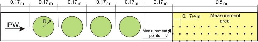
As stated in the introduction, the evaluation of the five than FDTD and MS. Furthermore, for larger scatterer
numerical methods considered is based on the knowledge of diameters, FEM shows no significant differences with
the estimated error of the global transmission coefficient as MFS or BEM. Indeed, for that case, the total number of
a function of the memory usage involved. And the varia- elements of BEM (or collocation points in MFS) required
tions of both, memory usage and estimated error is defined to discretize each scatterer is larger, and thus leads to a
for a particular range of variation of the main control larger memory usage. By contrast, for these larger diameter
parameter associated to each method. For the estimated scatterers, domain discretization methods such as FEM or
error of sound insulation in this final evaluation, we have FDTD benefit from a small reduction in mesh size (due to
obtained sj,conv as the average of the convergence transmis- the larger void in the mesh corresponding to the scatterers),
sion coefficients of the five methods. Figure 4 represents the and thus have improved performance.
estimated errors versus the memory usage for each diameter A deeper analysis shows that BEM and MFS methods
and method considered. As expected, the higher the offer very similar behaviour, as can be seen in the three
memory usage, the lower the estimated error. This trend graphs of Figure 4 and the convergence value of DLSI
is broken in the case of data with higher memory usage, (Tab. 2). Furthermore, in the case of d = 0.25 a there is
since the reference value for the error estimation has been almost an overlap of BEM and MFS curves, whereas in
obtained as the average of all the methods, so that no error d = 0.5 a and d = 0.75 a this overlap is only for small mem-
smaller than the estimated error between methods can be ory usages. Although this difference could seem to indicate
found. For the highest memory usage, the estimated error an irregular behaviour of one of these two methods, it is
values achieved are around one hundredth of a decibel. indeed due to the fact that the reference value for the error
As an objective evaluation criterion, the best results are estimation has been obtained as an average from several
those that offer the least estimated error involving lowest methods. Thus, the method whose convergence value of
memory usage. In other words, representing the estimated DLSI is closer to the average of the values of convergence
error as a function of the memory usage, the best methods will present a curve that converges better. In fact, for all
are those whose curves are closest to both axes. In some methods, the shape of the curve depends on the difference8 M.P. Peiró-Torres et al.: Acta Acustica 2021, 5, 28
(a) (b)
(c)
Figure 4. Estimated error of the global transmission coefficient s versus memory usage for all the studied methods: (a) d = 0.25 a;
(b) d = 0.5 a; (c) d = 0.75 a.
between the convergence DLSI value of each method and
the average of values of convergence, so their accuracy is
affected by the inaccuracy of the other methods.
It is also interesting to note that FEM performs better
when the scatterers diameter is larger, as the graph for
d = 0.75 a in Figure 4c shows. This may be due to the
way the mesh is defined. As it is the usual practice, a trian- Figure 5. FEM triangular flat mesh with a high growth factor
gular flat mesh has been used, which adapts to the geometry adapted to the scatterers geometry.
and has a growth function in order to achieve the desired
average size, being larger size in the areas far from the scat-
terers and smaller in areas close to them (see Fig. 5). Thus, to be simulated. However, this is not reflected in other
the size gradient will be more abrupt in d = 0.25 a than in methods. In the case of FDTD, the curve that defines its
d = 0.75 a leading to worse behaviour for smaller radius, estimated error as a function of the memory usage, is shifted
either because the mesh variability is an additional difficulty in the axis of the abscissa about 2–3 orders of magnitude
for the calculation or simply because of the excess memory with respect to the methods that give better results
usage needed to create the finer meshes surrounding the (BEM and MFS). This could be due to the fact that the
smaller obstacles. For this reason, the FEM curve of mesh is Cartesian. Therefore, a large mesh size implies a
d = 0.25 a, not only presents the worst performance with poor definition of the shape of the scatterers, and a poor
respect to its counterparts of other diameters, but it is also treatment of the wave dynamics, especially of its high
the one that presents a more irregular behaviour, with some frequencies. But since the method does not make an extra
increases in estimated error when rising memory usages, in adaptation of the mesh to the geometry of the scatterers,
low memory usages ranges. However, as the memory usage its curve is not affected by the size of the scatterers.
increases, i.e., the size of the mesh elements decreases, the Regarding the difference of several orders of magnitude
representation of the elements becomes more reliable and between the memory usage of the FDTD and that of the
the results present fewer estimated errors. MFS, BEM or FEM, it does not imply such a large decrease
Thus, FEM, as a domain discretization method, varies in the quality of the method, as might be apparent when
the quality of its calculation according to the way in which observing the presented plots. It may be noted that
the mesh elements are defined to adapt them to the domain frequency methods use the memory space multiple times,M.P. Peiró-Torres et al.: Acta Acustica 2021, 5, 28 9
as many times as frequencies to be considered. In FDTD, on that have not been considered here. For instance, only
the other hand, a unique time domain simulation is FEM and FDTD methods can be straightforwardly applied
made and then, by means of a Fourier transform, the trans- to simulate heterogeneous or non-linear media.
fer function is obtained. In our case, since we have taken
6 frequencies per each of the 18 one-third octave bands, Notations
the number of repetitions performed by the frequency
methods is 108. BEM Boundary Element Method
Finally, MS shows the worse curves between frequency FEM Finite Element Method
methods, as well as the most discrepant values in the sound FDTD Finite Difference Time Domain
insulation curves at convergence, shown in Figure 3. These MFS Method of Fundamental Solutions
evidences do not directly rule out the method, it simply MS Multiple Scattering
evidences that it is the least adapted to periodic structures. NRD Noise Reducing Device
In fact, it is the only method in which we could not use PML Perfectly Matched Layer
periodic conditions. SCAS Sonic Crystals Acoustic Screens
6 Conclusion Acknowledgments
The aim of the present work is to help the researchers in M.P.P.T is grateful for the support of pre-doctoral
the task of finding a simulation tool that provides Grant by the “Ministerio de Ciencia, Innovación y Univer-
maximum precision at the lowest memory usage for the sidades. Agencia Estatal de Investigación” of Spain
simulation of the acoustic performance of periodic struc- through reference no. DI-15-08100.
tures. It is essential to have a numerical method with such This work has been supported by the Ministerio de
characteristics when carrying out an optimization process, Ciencia, Innovación y Universidades, Spain, under grant
as this process involves a large number of simulations. RTI2018-096904-B-I00.
For the particular case raised in the study, both BEM This work was developed within the scope of the
and MFS are the best methods for performing optimization project with reference POCI-01-0247-FEDER-033691 –
processes and determining the acoustic performance of HLS – Hybrid Log Shield, supported by FEDER funds,
these periodic structures. Comparing the results offered through Portugal-2020 (PT2020) Programme, within
by FDTD and FEM, both volumetric methods but with the scope of SII&DT System, and by POCI Programme.
different calculation philosophy – since one is based on time This work was partly financed by FCT / MCTES through
domain and the other on frequency domain – we appreciate national funds (PIDDAC) under the R&D Unit Institute
that FEM effectively gives more accurate results requiring for Sustainability and Innovation in Structural Engineer-
less computational cost, but as explained above, this may ing (ISISE), under reference UIDB / 04029/2020.
be due to the parameter chosen by the authors to estimate
it, i.e. memory usage. If other parameters such as computa-
tional time had been taken into account, the results would Conflict of interest
have been different. As mentioned above, in that case the
type of implementation and the hardware used would have Author declared no conflict of interests.
been determinant.
The option of using calculation time to evaluate the per-
formance of methods was discarded because the calculation
References
time depends strongly on the particular code implementa- 1. R. Martínez-Sala, J. Sancho, J.V. Sánchez-Pérez, V. Gómez, J.
tion of the method and the particular computer on which Llinares, F. Meseguer: Sound attenuation by sculpture. Nature,
it is run. For further research, it is proposed to evaluate London 387 (1995) 241.
not only the memory usage, but also the computational 2. Y.Y. Chen, Z. Ye: Theoretical analysis of acoustic stop bands
time. Shorter calculation times would shorten the iteration in two-dimensional periodic scattering arrays. Physical
time in optimization processes, leading to greater efficiency Review E 64, 3 (2001) 036616.
of these processes and allowing them to be used as compet- 3. M.S. Kushwaha: Stop-bands for periodic metallic rods:
sculptures that can filter the noise. Applied Physics Letters
itive design tools. It could also be interesting to include in 70, 24 (1997) 3218–3220.
the simulation processes absorbent materials and resonant 4. J.V. Sánchez-Pérez, C. Rubio, R. Martínez-Sala, R. Sánchez-
cavities in the acoustic scatterers, which will improve the Grandia, V. Gómez: Acoustic barriers based on periodic
acoustic performance of the device. arrays of scatterers. Applied Physics Letters 81 (2002) 5240.
It could be premature to extrapolate the results 5. M.P. Peiró-Torres, M.P. Navarro, M. Ferri, J.M. Bravo, J.V.
obtained and discussed in this work to other geometries Sánchez-Pérez, J. Redondo: Sonic crystals acoustic screens
and diffusers. Applied Acoustics 148 (2019) 399–408.
since each of the methods considered has its own peculiari-
6. EN 1793–2:2018: Road traffic noise reducing devices – Test
ties, and therefore can be better adapted to particularities method for determining the acoustic performance – Part 2:
such as resonant cavities or absorbents. This may make Intrinsic characteristics of airborne sound insulation under
one method or another more suitable in other situations diffuse sound field conditions.10 M.P. Peiró-Torres et al.: Acta Acustica 2021, 5, 28
7. EN 1793–6:2018: Road traffic noise reducing devices -Test 20. F. Koussa, J. Defrance, P. Jean, P. Blanc-Benon: Acoustical
method for determining the acoustic performance – Part 6: efficiency of a sonic crystal assisted noise barrier. Acta
Intrinsic characteristics – In situ values of airborne sound Acustica United with Acustica 99, 3 (2013) 399–409.
insulation under direct sound field conditions. 21. H.F. Gao, T. Matsumoto, T. Takahashi, H. Isakari: Analysis
8. F. Zaviska: Uber die beugung elektromagnetischer wellen an of band structure for 2D acoustic phononic structure by BEM
parallelen, unendlich langen kreisylindern. Annalen der and the block SS method. CMES – Computer Modeling in
Physik 345, 5 (1913) 1023–1056. Engineering & Sciences 90, 4 (2013) 283–301.
9. W. Von Ignatowsky: Zur theorie der gitter. Annalen der 22. M. Karimi, P. Croaker, N. Kessissoglou: Boundary element
Physik. 349, 11 (1914) 369–436. solution for periodic acoustic problems. Journal of Sound and
10. V. Twersky: On scattering of waves by the infinite grating of Vibration 360 (2016) 129–139.
circular cylinders. IRE Trans. on Antennas and Propagation 23. G. Fairweather, A. Karageorghis, P.A. Martin: The method
10 (1962) 737. of fundamental solutions for scattering and radiation prob-
11. S. Guenneau, A.B. Movchan: Analysis of elastic band lems. Engineering Analysis with Boundary Elements 27
structures for oblique incidence. Archive for Rational (2003) 759–769.
Mechanics and Analysis 171, 1 (2004) 129–150. 24. M. Martins, L. Godinho, L. Picado-Santos: Numerical
12. Y.F. Wang, Y.S. Wahng, X.X. Su: Large bandaps of two- evaluation of sound attenuation provided by periodic struc-
dimensional phononic crystals with cross-like holes. Journal tures. Archives of Acoustics 38, 4 (2013) 503–516.
of Applied Physics 110, 11 (2011) 113520. 25. P.G. Santos, J. Carbajo, L. Godinho, J. Ramis: Sound
13. M. Liu, J. Xiang, H. Gao, Y. Jiang, Y. Zhou, F. Li: Research propagation analysis on sonic crystal elastic structures using
on band structure of one-dimensional phononic crystals the Method of Fundamental Solutions (MFS). CMC: Com-
based on wavelet finite element method. CMES – Computer puters, Materials & Continua 43, 2 (2014) 109–136.
Modeling in Engineering & Sciences 97, 5 (2014) 425–436. 26. L. Godinho, P. Amado-Mendes, A. Pereira, D. Soares Jr: An
14. J.V. Sánchez-Pérez, C. Rubio-Michavila, S. Castiñeira- efficient MFS formulation for the analysis of acoustic scatter-
Ibáñez: Towards the development of a software to design ing by periodic structures. Journal of Theoretical and Com-
acoustic barriers based on sonic crystals: an overlapping putational Acoustics 26, 1 (2018) 1850003–1–1850003–22.
model. Proceedings of Euronoise 2015 (2015) 2367–2371. 27. L. Godinho, J. Redondo, P. Amado-Mendes, The method of
15. K.S. Yee: Numerical solution of initial boundary value prob- fundamental solutions for the analysis of infinite 3D sonic
lems involving Maxwell’s equations in isotropic media. IEEE crystals. Engineering Analysis with Boundary Elements 98
Transactions on Antennas Propagation 14 (1966) 302–307. (2018) 172–183.
16. J.G. Maloney, K.E. Cummings: Adaption of FDTD tech- 28. EN 1793–3:1998: Road traffic noise reducing devices. Test
niques to acoustic modelling. Rev. Prog. Applied Computa- method for determining the acoustic performance. Normal-
tional Electromagnetics 2 (1995) 724. ized traffic noise spectrum.
17. Y. Cao, Z. Hou, Y. Liu: Convergence problem of plane-wave 29. J. António, A. Tadeu, L. Godinho: A three-dimensional
expansion method for phononic crystals. Physics Letters A acoustics model using the method of fundamental solutions.
327, 2 (2004) 247–253. Engineering Analysis with Boundary Elements 32, 6 (2008)
18. T. Miyashita: Sonic crystals and sonic wave-guides. 525–531.
Measurement Science and Technology 16, 5 (2005) R47. 30. T.W. Wu, Editor: Boundary element acoustics: fundamen-
19. F.L. Li, Y.S. Wang, C. Zhang, G.L. Yu: Band-gap calcula- tals and computer codes. WIT Press, Southampton, 2000.
tions of two-dimensional solid–fluid phononic crystals with 31. Y.Y. Chen, Z. Ye: Theoretical analysis of acoustic stop bands
the boundary element method. Wave Motion 50, 3 (2013) in two-dimensional periodic scattering arrays. Physical
525–541. Review E 64, 3 (2001) 036616.
Cite this article as: Peiró-Torres M.P, Ferri L.M, Godinho L.M Amado-Mendes P, Jose Vea Folch F, et al. 2021. Normal incidence
sound insulation provided by Sonic Crystal Acoustic Screens made from rigid scatterers – assessment of different simulation
methods. Acta Acustica, 5, 28.You can also read