Nortec SE-Series Installation and Operation Manual - Condair
←
→
Page content transcription
If your browser does not render page correctly, please read the page content below
Important: Read and save these instructions. This guide to be left with equipment.

                                                Nortec
                                              SE-Series
                                                        Installation and
                                                      Operation Manual
                                                        Includes installation, operation,
                                                      maintenance, and troubleshooting
                                                             information for your indoor
                                                       Nortec SETC B+ and Nortec SEP
                                                             steam exchange humidifier

2552940-F | 31/MAY/2021
Thank you for choosing Condair.

 INSTALLATION DATE (MM/DD/YYYY)

 MODEL #

 SERIAL #

Proprietary Notice
This document and the information disclosed herein are proprietary data of Condair LTD. Neither this
document nor the information contained herein shall be reproduced used, or disclosed to others without the
written authorization of Condair LTD., except to the extent required for installation or maintenance of
recipient’s equipment. All references to the Condair name should be taken as referring to Condair LTD.
Liability Notice
Condair does not accept any liability for installations of humidity equipment installed by unqualified personnel
or the use of parts/components/equipment that are not authorized or approved by Condair.

Copyright Notice
Copyright 2021, Condair LTD. All rights reserved.
Contents

      1 Introduction                        43Operation
2    Receiving and Unpacking           44   Nortec SETC LED Status Lights
3    Humidifier Components             44   Nortec SEP LED Status Lights
5    Nortec SETC/P Models              45   How the Humidifier Works
6    Options and Accessories           49   Nortec SETC Humidifier Configuration
      9 Installation                   60   Nortec SEP Humidifier Configuration
10   Typical Humidifier Installation        63Maintenance and
11   Location                               Servicing
12   Mounting                          64   Required Maintenance

14   Plumbing                          65   Maintenance Schedule

15   Boiler Steam and Boiler           69   Maintenance Shutdown and
     Condensate Return                      Extended Shutdown

17   Steam Lines and Condensate        70   Maintenance Checklist
     Returns                                71Troubleshooting
22   Electrical                        73   General Troubleshooting

23   External Controls                 76   Nortec SETC Warnings and Faults

32   Options and Accessories           82   SEP Faults
      33Start Up                       83   Wiring Diagrams
34   Installation Check                   85Spare Parts
35   Nortec SETC User Interface        96 Warranty
36   Start Up Procedure
37   Status Screens
39   Digital Controls
41   Start Up Checklists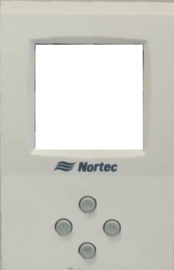
Introduction

          CAUTION: Servicing
          •   Disconnect main power before any servicing.
          •   Shut off pressurized steam supply and ensure steam pressure is safely relieved
              before any servicing of pressurized steam components.
          •   The electrical compartment contains high voltage components and wiring. Access
              should be limited to authorized personnel only.
          •   During and following operation of the humidifier, the steam and components in
              contact with the steam such as the tank, blower pack, steam lines, steam
              distributors, and condensate lines can become hot and can burn if touched.
          •   Condair does not accept any liability for installations of humidity equipment
              installed by unqualified personnel or the use of parts/components/equipment
              that are not authorized or approved by Condair.

          CAUTION: Electrical
          •   All electrical work should be done according to local electrical code.
          •   Electrical connection to be performed by a licensed electrician.

          CAUTION: Plumbing / Steam Lines
          • Plumbing to be performed by a licensed plumber.
          • Pressurized steam line installation to be performed by a qualified installer.
          • Drain water from humidifier can be very hot. Do not drain to public sink.
          • All plumbing and pressurized steam supply line work should be done according to
            local plumbing code.

          CAUTION: Installation
          •   Do not mount on hot surfaces
          •   Do not mount in area where freezing can occur
          •   Do not mount on vibrating surface
          •   The Nortec SETC/P produces steam at atmospheric pressure no devices which
              could block steam output should be connected to the steam outlet.
          •   Steam output lines must be installed so that no restriction can produce
              backpressure in the humidifier.
          •   Regardless of selecting On/Off or modulating control method, Condair humidifiers
              must have a closed circuit across its On/Off security loop control terminal to
              operate. Condair highly recommends the use of a high limit humidistat and an air
              proving switch in series for this function.
          •   Unit damage caused by water quality outside of the specified ranges is not
              covered under warranty.

1 | Introduction
Receiving and Unpacking
1 Check packing slip to ensure ALL material has been delivered.
2 All material shortages are to be reported to Condair within 48 hours from receipt of goods.
Condair assumes no responsibility for any material shortages beyond this period.
Note: A steam valve, actuator, and wye strainer are shipped along with the SETC/P
humidifier but in separate small boxes.
3 Inspect shipment for damage and note damages on shipping waybill accordingly.
4 After unpacking, inspect equipment for damage and if damage is found, notify the shipper
promptly.
5 All Condair products are shipped on an FOB factory basis. Any and all damage, breakage
or loss claims are to be made directly to the shipping company.
Before Installation
1 Ensure that available voltage and phase corresponds with humidifier voltage and phase as
indicated on humidifier’s specification label.
2 If steam supply is from a Medium or High Pressure boiler ensure supply steam line includes
a relief valve to prevent supply pressure from exceeding 15 psig.
3 Ensure means for returning boiler steam condensate to boiler at atmospheric pressure are
available.
4 Ensure sufficient clearances will be available as described in Location on page 11.
5 Ensure steam lines can be routed to distributor SAM-e manifold or blower pack as described
in Steam Lines and Condensate Returns on page 17.
6 Report any discrepancy immediately to the site engineer.
Figure 1: Specification Label Location
Introduction | 2Humidifier Components
Float Chamber Display and Keypad Control Terminal Strip
Tank
On/Off Switch
Clean Out
Port
Remote Relay
Heat Board
Exchanger
Gasket
Driver Board
High Voltage
Terminal Block
Base
Manual Drain Switch Transformer
Heat Steam Outlet Vacuum Break
Exchangers Fill Box
(Faceplate) Steam Inlet
Total Controller
(Boiler Steam)
Actuator
Wye Strainer
CV Valve
Fill Valve
Drain Outlet
P Trap
Condensate Drain
(Boiler Steam)
Auxiliary Drain
Outlet
Drain Pump
Steam Trap Mixing Box
Figure 2: Nortec SETC Humidifier Components
3 | IntroductionDescription of Components
Table 1: Humidifier Components
Component Function of Component
Actuator Opens and closes the CV valve in proportion to demand for steam.
Auxiliary Drain Drains water from tank in case of pump failure.
Outlet
Base Provides an integrated floor support for the humidifier.
Clean Out Port Provides access to clean scale from the tank and heat exchanger.
Condensate Drain Drains condensate formed from boiler steam in the heat exchanger(s)
Control Terminal Terminal strip for connecting external controls and blower pack to
Strip humidifier.
CV Valve Controls the amount of steam allowed into the heat exchanger which in
turn controls the output of the humidifier.
Display and Keypad User interface for configuring the humidifier.
Drain Outlet Drain port used for draining water from the humidifier tank.
Drain Pump Drains water from humidifier.
Driver Board Provides input and output connections to humidifier components.
Fill Box Provides an air gap for backflow prevention.
Fill Valve Controls flow of water into humidifier.
Float Chamber Measures water level in the humidifier tank.
Gasket Seals heat exchanger face plate and clean out port cover to tank.
Heat Exchanger(s) Exchanges energy from boiler steam to the tank water to produce steam
for humidification. The faceplate mounts the heat exchanger to the tank.
High Voltage Primary power connection from remote disconnect to humidifier.
Terminal Block
Manual Drain Switch Manually activates pump to drain water from the tank.
Mixing Box Blends hot tank water with cool fill water to provide drain water cooling.
On/Off Switch Turns power On/Off to humidifier controller. Note: Turn off humidifier
disconnect to shut off primary power to the humidifier.
P Trap Prevents steam from flowing out the drain outlet.
Remote Relay Provides a terminal strip to dry contacts which open/close to indicate the
Board humidifier is on, humidifying, needs service, or is in a fault condition.
Steam Inlet Connection for boiler steam, it is connected to the heat exchangers.
Steam Outlet Connect to steam line with steam hose.
Steam Trap Drains condensate from the heat exchanger without letting boiler steam
escape to drain.
Tank Holds the water used to generate clean steam for humidification.
Total Controller Controls all functions of the humidifier’s operation and provides user
interface for configuration of the humidifier.
Transformer Steps primary voltage down to 24 VAC for the controller and internal
components such as the fill valve and drain valve.
Vacuum Break Prevents a siphon from occurring when the drain pump is stopped.
Wye Strainer Protects CV valve and other system components from dirt and rust in the
piping system.
Introduction | 4Nortec SETC/P Models
The Nortec SETC with its Total Controller and state-of-the-art features and options is the most
advanced steam exchange humidifier available. The base model Nortec SEP provides steady
and reliable humidification using the same proven heat exchanger technology as the
Nortec SETC. The Nortec SETC/P is available in capacities ranging from 50 lb/hr (23 kg/hr) to
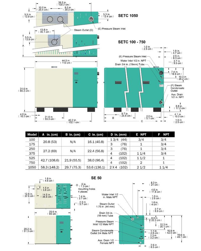
1050 lb/hr (475 kg/hr). Nortec SETC/P humidifiers are packaged in five different cabinets
depending on their capacity. Figure 3: Nortec SETC/P Models shows the configuration and
relative size of the five different cabinets. Table 3 provides specifications for the
Nortec SETC/P product line.
SETC50 Note:
SE 750 has
2 steam outlets SE 525-750
SE 100-175
SE 1050
SE 250-375
Figure 3: Nortec SETC/P Models
The Nortec SE 50, 100, 175, 250, and 375 all have a single heat exchanger. The Nortec SE
525 and 750 have two heat exchangers. The Nortec SE 1050 has three heat exchangers. All
models have a single pressurized steam inlet and condensate drain with internal manifold
connecting separate heat exchangers if they are present.
5 | IntroductionOutdoor Model (Nortec SETC Only)
The outdoor model of the Nortec SETC provides a weatherproof enclosure that allows the Nortec
SETC to be installed on rooftops in moderately cool climates. Refer to the Nortec SETC
installation manual that is provided with the outdoor model to insure proper installation.
Options and Accessories
Condair provides a complete line of options and accessories for every humidification application.
The following options and accessories are available and may have been delivered with your
Nortec SETC/P humidifier. Refer to the installation instructions that came with the accessories
for their proper installation and operation.
Table 2: Options and Accessories
Option / Accessory Used For
Freeze Protection Package Emptying the tank in case of fault or power failure to prevent
(Nortec SETC Only) freezing. (Factory installed)
Floor Stand Supporting the humidifier 27 inches above the floor (height can be
reduced by cutting legs of floor stand). (field assembled)
Ceiling Mounting Kit (Nortec SE50 Only) Providing a drain pan and support brackets for mounting an
Nortec SE50 unit from the ceiling.
Steam Distributors Adding steam into air ducts
Remote Blower Pack Adding steam into a space remote from the humidifier.
SAM-e Steam Distribution Manifold Adding steam into air ducts where short absorption is required.
Digital or Analog Control Humidistats Controlling the output of the humidifier based on sensed RH (can
be mounted in the space being humidified or in the duct).
Digital RH Transducers Communicating RH in a space or duct to the humidifier
Digital or Analog High Limit Humidistats Preventing over humidification in a duct by shutting down or
throttling down the humidifier when duct RH gets high.
Air Proving Switches Insuring humidification only occurs when air is moving in a duct.
Condair LINKS 2 (Nortec SETC Only) Connecting the humidifier to a building management interface.
hardware allows control of the humidifier via BACnet, Lonworks,
Johnson N2, or Modbus.
Condair OnLine (Nortec SETC Only) User and factory monitoring and configuration of the humidifier via
the internet.
Introduction | 6Table 3: Nortec SETC/P Specifications
Nortec SETC SEP CV CV Valve, Cond- Net/Full Required Required Electrical
Model Part No Part No. Valve Steam ensate Weight fill line Drain
Inlet, Wye Port lb (kg) flow capacity
Port (NPT) (NPT) gal (l) gal (l)
/min /min
125/180 Voltage
50 2552765 2520383 2.8 1/2 3/4
(57/82) 110-120
100 2550073 2525132 5.5 3/4 3/4 267/423 Phase
175 2550074 2525133 10 1 3/4 (121/192) 2.6 (10) 5.2 (20) 1
250 2550075 2525134 12 1 3/4 355/599 Amps
375 2550076 2525135 20 1 1/4 3/4 (161/272) 1.25 A
Power
525 2550077 2553312 28 1 1/2 1 529/992
0.15 KW
750 2550078 2553313 40 2 1 (240/450)
Max
703/1384 4.5 (17) 8 (29) Disconnect
1050 2550080 2525139 77 2, 2 1/2, 1 1/4 (318/628)
2 1/2 15 A
Table 4: Nortec SETC/P Capacities and Water Consumption
Nortec *Supply *Max Output Approximate **Water **Drain Volume
Model Steam lb/hr (kg/hr) Boiler Steam Consumption gal (l) /hr
Pressure Consumption gal (l) /hr
(psig) lb/hr (kg/hr)
5 13 (6) 15 (7) 2.3 (9) 0.8 (3)
50 10 32 (14) 36 (16) 5.7 (21) 1.9 (7)
15 50 (23) 58 (26) 9.0 (34) 3.0 (11)
5 26 (12) 30 (14) 4.7 (18) 1.6 (6)
100 10 63 (29) 72 (33) 11.3 (43) 3.8 (14)
15 100 (45) 115 (52) 18.0 (68) 6.0 (23)
5 46 (21) 52 (24) 8.2 (31) 2.7 (10)
175 10 110 (50) 127 (58) 19.8 (75) 6.6 (25)
15 175 (80) 201 (91) 31.5 (119) 10.5 (40)
5 65 (30) 75 (34) 11.7 (44) 3.9 (15)
250 10 158 (72) 181 (82) 28.3 (107) 9.4 (36)
15 250 (114) 288 (131) 44.9 (170) 15.0 (57)
5 98 (44) 112 (51) 17.5 (66) 5.8 (22)
375 10 236 (107) 272 (123) 42.5 (161) 14.2 (54)
15 375 (170) 431 (196) 67.4 (255) 22.5 (85)
5 137 (62) 157 (71) 24.5 (93) 8.2 (31)
525 10 331 (150) 380 (173) 59.5 (225) 19.8 (75)
15 525 (239) 604 (274) 94.4 (357) 31.5 (119)
5 195 (89) 224 (102) 35.1 (133) 11.7 (44)
750 10 473 (215) 543 (247) 84.9 (321) 28.3 (107)
15 750 (341) 863 (392) 134.8 (510) 44.9 (170)
5 273 (124) 314 (143) 49.1 (186) 16.4 (62)
1050 10 662 (301) 761 (346) 118.9 (450) 39.6 (150)
15 1050 (477) 1208 (549) 188.7 (714) 62.9 (238)
* Supply steam pressure must be present at the CV valve to achieve rated output
** At maximum output , 25% blow down, and with drain water cooling activated
7 | InstallationNortec
Nortec
Nortec
Installation | 8Installation
10 Typical Humidifier Installation
11 Location
12 Mounting on Optional Stand
13 Ceiling Mounting (Nortec SE50 Only)
14 Plumbing
15 Boiler Steam and Boiler Condensate Return
17 Steam Lines and Condensate Returns
22 Electrical
23 External Controls
23 Control Wiring
23 Control Location
24 On/Off Control Wiring
25 Modulating Control Wiring
27 Transducer Control Wiring
28 Optional Outdoor Temperature Reset
29 CV Valve Actuator Wiring
30 Remote Relay Board Wiring
31 Staged Modulation Wiring (Nortec SETC Only)
32 Options and Accessories
32 Remote Blower Pack
9 | InstallationTypical Humidifier Installation
SAM-e Distribution Manifold
1ft (30 cm)
2 in
(5 cm)
min.
36 in (91 cm) min.
Steam Top Clearance
Distribution (0 in SE 50)
Pg 17 30 in 30 in 30 in
(76 cm) (76 cm) (76 cm)
Min. Min. Side Min. Front
SE 1050 Clearance Clearance
Pressurized steam
Location supply
1 ft (30 cm) min.
Mounting
Pg 11
Water supply
30-80 psig
Plumbing Air gap
Pg 14
Boiler
Steam Tank drain
Pg 15
Condensate return to boiler
Modulation
Controls On/Off 1- 24VAC
2- On/Off Loop Dedicated Circuit Breaker or
Controls
Ground
3- Ctrl Ground Disconnect
4- Control Signal
Controls
L1
5- Limit Signal
N
Pg 23 6- 5 VDC
7- Ground SETC/P
8- Tank Blow Down
9- Ground
EXT
10- Actuator
11- Actuator
12- 0-10 VDC Out
EXT
SETC/P
Electrical
Pg 22
Figure 5: Typical Humidifier Installation
Installation | 10Location
The Nortec SE series humidifiers are designed to be either floor mounted or stand mounted
(stand optional). Nortec SE 50 models can also be ceiling mounted with the optional ceiling
installation kit, part number 2520345.
• Install only in areas with ambient temperature 41-104 °F (5 – 40 °C) relative humidity 5 -
95% (non condensing).
• Ensure mounting surface is strong enough to support the full weight of the humidifier and
accessories (see Table 3: Nortec SETC/P Specifications).
• Install in location where electrical power, boiler steam, and drain can be connected to the
humidifier.
• When possible install below the steam distributor. If mounted above the steam distributor
take care to provide proper steam line routing and proper condensate traps.
• DO NOT locate the humidifier any further then absolutely necessary from the steam
distributor location as net output will be reduced as a result of heat loss through the steam
line.
• Condensate drain is located close to the bottom of the humidifier. Locate the unit so that
condensate line slopes down to boiler or use pump (by others) to lift to boiler. Use stand if
necessary.
• Avoid mounting humidifier on combustible surfaces including (but not limited to) carpet, tile,
or certain insulating materials.
• Clearance dimensions shown are for reference only and are the minimum required for
maintenance of the humidifier. Consult local and national codes before final location and
installation. Condair does not accept responsibility for installation code violations.
Note:. Condensate drain line must be sloped downward to boiler condensate return.
Use pump (by others) or stand (optional) if necessary.
As Close as
Possible to Steam 36 in. (91 cm) Min.
Distributor Top Clearance
5-95% (0 in. for SE50 only)
Mount
Humidifier Level
30 in. 30 in. 30 in.
(76 cm) (76 cm) (76 cm)
Min. Min. Side Min. Front
SE 1050 Clearance Clearance
only
Condensate drain
line must be
sloped down, do
not use to lift
condensate
Figure 6: Installation Location / Clearance
11 | InstallationMounting on Optional Stand
The optional Nortec SE floor stand positions the Nortec SE humidifier at a convenient working
height and provides additional clearances for sloping drains. The stand must be assembled
at site.
• Assemble the stand according to the instructions that are provided with it.
• Ensure the stand and humidifier are installed on a level surface
• Permanently secure the stand to the floor via the holes in the leg support plates following
any local codes or regulations.
Mount stand on level surface
Ensure humidifier is Level
Fasten Nortec SE humidifier
to stand with bolts, lock
washers, and nuts provided.
Tighten
to 200 in-lb (22.6 Nm).
Note: Center support only
present on Nortec SE
525 and larger.
Secure stand to floor
four places. (hardware by
others)
Figure 7: Mounting on Optional Stand
Note: The humidifier must be secured to the stand (hardware provided) and the stand
must be secured to the floor (hardware by others).
Installation | 12Ceiling Mounting (Nortec SE50 Only)
Note:. The Nortec SE50 requires regular maintenance including removal of scale
from the heat exchanger and tank. Make sure it is installed in a location where
the maintenance can be performed.
12.8 in.
(32.6 cm)
Anchor 3/8 in (M10)
support rods to ceiling
(by others)
Sloped drain
1/2 in. pipe
(by others)
Support rods and hardware
(by others) must not extend
below support bracket flange.
Figure 8: Ceiling Mounting the Nortec SE50
Condair offers an optional ceiling mounting kit (part number 2520345) which allows the Nortec
SE50 to be ceiling mounted with zero clearance to the ceiling. Follow the following guidelines
for installation.
• Follow the instructions provided with the ceiling mounting kit.
• Install in a location where regular maintenance can be performed. Provide clearance as
shown in Figure 6: Installation Location / Clearance.
• The Nortec SE50 weighs 180 lb (82 kg) when filled with water and without any
accessories or piping. It is the installer’s responsibility to calculate the total weight
which must be supported, to ensure the ceiling structure is adequate, and to install
support rods and to connect drain pan per local codes and regulations.
• The humidifier cannot be used as a structural member. All piping connected to the unit
must be supported independently.
• A drain line emptying into an open drain must be connected to the ceiling kit drain pan.
Condair recommends a 1/2 in. pipe with sufficient slope to ensure any water collected in
the pan will drain from it.
13 | InstallationPlumbing
0.75 in. (19 mm). OD
un-threaded drain outlet
Connect with hose cuff
and hose clamps.
1/2 in. NPT
Use union to connect
supply pipe to unit.
Always install a water
shut-off valve.
Air gap required.
2 1/2 in. to 1 1/4 in. copper
reducer is ideal.
Hose/line must not touch
the bottom of the funnel.
Min. 1 1/4 in. OD drain line.
Slope down. Increase size
if combining multiple drains.
Axillary drain, 1/2 in. female NPT
For draining tank without pump. Leave
valve closed except if freeze protection is installed.
*Pipe, unions, and water shut-off valve not supplied by Condair.
Figure 9: Water Supply and Drain Connection
Note:
• Drain Water is very hot, do not use plastic pipe for drain or condensate lines, do not
drain to public sink. Route to floor drain or equivalent.
• Supply cold potable water, deionized water or reverse osmosis water at 30 - 80 PSIG.
Hardness 5-7 grain or 90 – 120 mg/l (as Ca+2 as CaCO3)
Total Dissolved Solvents (TDS) 0.5-3 mg/l or Conductivity 1 to 70 mho/cm
Chlorides 0-25 ppm PH 7.2-8.5 Alkalinity 30-130 mg/l (as CaCO3)
• All water supply and drain line connections must be installed in accordance with local
plumbing codes.
• See Table 3 and Table 4 on page 7 for supply water flow requirements.
• Install water shut off valve and union before humidifier to facilitate servicing.
• Insure drain line is adequately sized to provide free and easy draining and that an air gap is
installed as shown. See Table 3 and Table 4 on page 7 for flow requirements.
• Auxiliary drain connection with manual shut off valve is recommended for all units. Valve to
be left closed on units without freeze protection option installed. Valve to be left open on
units with freeze protection option installed except during servicing.
• High hardness or silica content supply water may require increased maintenance.
• Unit damage caused by water quality outside of the specified ranges is not covered under
warranty.
Installation | 14Boiler Steam and Boiler Condensate Return
Note:.
• Pressurized steam line installation to be performed by a qualified installer.
• Damage to Nortec SE heat exchanger will occur if it is exposed to pressure above
20 psi.. A safety relief valve must be installed to prevent the Nortec SE from being
exposed to pressure in excess of 15 psi when the Nortec SE is connected to a
medium or high pressure boiler via a pressure reducing valve.
• The steam supply line must be designed to provide design pressure at the CV valve
when there is 100 % demand (CV valve completely open). Pressure losses in the
steam supply line will reduce Nortec SE output.
• Condensate must be drained to a non-pressurized boiler condensate return line.
Boiler steam supply
6 in. line. Max 15 psi, Min 5 psi
(15 cm)
measured at CV Valve
Max
Actuator
Boiler steam
inlet port location
on Nortec SE 1050 CV Valve
(see table 3) Pressure
gauge (optional)
F&T Trap
Wye Strainer Isolation Valve
Boiler steam
inlet port
(see table 3)
Condensate Drain
Port (see table 3)
Condensate drain line.
Gravity feed to boiler.
Use pump if condensate
must be lifted.
Note: Condair supplies CV valve, Not pressurized Pressurized condensate
actuator and wye strainer. All other condensate header header
components and fittings by others. (slope down)
Figure 10: Nortec SE Boiler Steam and Condensate Connection
15 | InstallationCondair supplies a CV valve, actuator and wye strainer with each Nortec SE humidifier. The port
sizes of the CV valve, boiler steam inlet port, and condensate drain port are given in Table
3: Nortec SETC/P Specifications on page 7. Follow the following guidelines for installation.
• All steam line connections must be installed in accordance with local codes.
• Install the CV valve actuator following the procedure in Figure 11: CV Valve Actuator
Installation after the CV valve is installed on the steam line. Wire the actuator as described
in CV Valve Actuator Wiring on page 29.
• Boiler steam supply line design is the responsibility of the installer. The boiler steam supply
line must be designed so that that design pressure is present at the CV valve when the CV
valve is completely open (100% demand). The diameter of the supply line up to the wye
strainer may have to be oversized to insure proper steam pressure.
• The Nortec SE will operate on supply steam pressures between 5 and 15 psi measured at
the CV valve. Lower steam supply pressures will result in lower output. See Table
4: Nortec SETC/P Capacities and Water Consumption on page 7 for capacities at different
supply pressures.
• If condensate cannot be gravity fed to the boiler then a pump must be used to lift the
condensate. See Spirax Sarco (www.spiraxsarco.com) and others for pumps and additional
information on condensate management.
Caution: Condensate leaves the steam traps inside the Nortec SE under slight pressure.
Steam flash could occur in the condensate drain line.
• The boiler steam and condensate connections are independent. Boiler steam condensate
should be returned to the boiler and should not be mixed with water from the tank drain.
• The steam supply pressure can be entered into the Nortec SETC control software to provide
display of unit output. See Pressure Based on page 56.
2 turns then
push in and
Actuator 1/8 turn to lock
Install jam nut Install stem
and lock washer extension
Raise valve
stem to full up
1/2 in. (1.2 cm)
min.
Install and
tighten
mounting nut
CV Valve
Turn stem
extension
until holes Insert Tighten jam nut
line up connecting against stem extension
pin
Figure 11: CV Valve Actuator Installation
Installation | 16Steam Lines and Condensate Returns
MAIN RULES FOR ATMOSPHERIC STEAM LINES
• Slope the steam lines.
• Trap condensate (Use full size ‘T’ for Traps).
• Steam lines must not have any restrictions which could cause back pressure.
• Insulate with 1.0 in. (2.5 cm) pipe insulation.
• Follow recommended materials, size and length see tables.
Use Appropriate Slope Insulate Pipe
10 Degrees
2 in.
(5 cm)
1 ft (30 cm)
2 Degrees
Steam Direction
0.5 in. 1 in. (2.5 cm) pipe
(12 mm) 1ft (30 cm) insulation
Figure 12: Main Steam Line Requirements
Table 5: Recommended Steam Line Material
Steam Line Steam Line Length
Material Lb/hr (kg/hr) ft m Steam Line Description
0-100 (0-45) 0-90 0-27 1 1/2 in. MED-L Tubing (1.625 in. OD)
Copper Tube 101-250 (46-113) 0-180 0-54 3 in. MED-L Tubing (3.125 in. OD)
251-650 (114-295) 0-260 0-79 **4 in. MED-L Tubing (4.125 in. OD)
0-100 (0-45) 0-90 0-27 1.75 inch Tube x 0.065 inch thick wall
*Stainless Steel
101-250 (46-113) 0-180 0-54 3 inch Tube x 0.065 inch thick wall
Tube
251-650 (114-295) 0-260 0-79 **4 inch Tube x 0.065 inch thick wall
Condair Hose 31-100 (14-45)**Table 6: Maximum Recommended Length of Steam Line
Unit Size Steam Output Steam Outlet Maximum Possible Loss Possible Loss atLoss at
Possible
and Line Size Length Max. Length
Max. length
lb/hr (kg/hr)
lb/hr (kg/hr) copper (SST) ft (m) lb/hr/ft (kg/hr/m) lb/hr (kg/hr)
50 50 (23) 1 1/2 (1 3/4) 37 (11) 0.11 (0.16) 4 (2)
100 100 (45) 1 1/2 (1 3/4) 90 (27) 0.11 (0.16) 10 (4.5)
175 175 (80) 3 (3) 90 (27) 0.16 (0.24) 14 (6.5)
250 250 (114) 3 (3) 180 (55) 0.16 (0.24) 28 (13)
375 375 (170) 4 (4) 180 (55) 0.22 (0.33) 39 (18)
525 525 (239) 4 (4) 220 (67) 0.22 (0.33) 48 (22)
750 750 (341) 2X 4 (4) 260 (79) 0.44 (0.66) 114 (52)
1050 1050 (477) 2X 4 (4) 260 (79) 0.44 (0.66) 114 (52)
NOTE: See Table 7 for equivalent length of common fittings.
Table 7: Equivalent Length of Some Common Fittings
Tube Diameter 90 Degree 45 Degree Elbow Side Outlet Tee Gate Valve GlobeValve
Control Valve
in. Elbow ft (m) ft (m) ft (m) ft (m) ft ft
(m)(m)
1 1/2 or 1 3/4 3.5 (1) 1.75 (0.5) 7 (2.1) 0.8 (2.4) 34 (10)
3 5 (1.5) 2.5 (0.75) 11 (3.3) 1.1 (3.1) 54 (16)
4 8 (2.4) 4 (1.2) 15 (4.5) 1.6
4 8 (2.4) 4 (1.2) 15 (4.5) 1.6 (0.5) 80 (24)
Tee is same size
Use a full size tee, not a 90
as steam line
degree elbow for vertical
to horizontal transitions.
12 in. (30 cm)
min drop to
top of ‘P’ Trap
‘P’ Traps Use:
- Condair 0.375 in condensate hose .
P Trap - 1/4 in Med-L copper tubing, or
min 8 in. - 0.375 in stainless steel tubing
(20 cm)
plus duct
static pressure
Condensate drains must be sloped down.
Route
Figure to humidifier fill
13: Condensate cup if possible.
Traps
Note: Condensate should not be routed to a sink used frequently by personnel. Route to
a floor drain or equivalent. Condensate normally cools in traps but is still hot. A SAM-e or
larger steam line generates more condensate and water may not cool in the trap. A drain
water cooler option may be installed if required by code.
Installation | 18Calculated absorption
distance to any obstruction
or 8-10 ft (2.4 - 3 m)
if unknown
2 x duct
height min.
2/3 Duct
height
12 in.
(30 cm)
min.
Mount distributor
to side of duct
Figure 14: Distributor Location in Duct
Note:
Refer to distributor or SAM-e installation manuals for detailed installation instructions.
Hose cuff
with clamps
Insulated copper
steam line. Support 1 ft (30 cm)
so weight is not on
steam outlet. 2 in. (5 cm)
min.
Condensate line
1 ft (30 cm)
min. before
anybend ‘P’ Trap
To drain
Use steam hose between
steam outlet and steam line.
Figure 15: SAM-e/Steam Distributor Above Humidifier (Copper Steam Line Shown)
19 | InstallationHose will soften
over time
proper support
Min 12 in. Is necessary
(30 cm)
radius
Support Brackets
Install Condensate Tee
Before Distributor
1 ft (30 cm)
min. Before
any bend
1 ft (30 cm)
‘P’ Trap min.
‘P’ Trap
To drain
To drain
Figure 16: Steam Distributor/SAM-e Below Humidifier (Hose Shown)
1 ft (30 cm)
0.5 in. (1.2 cm) min.
1ft (30 cm)
min. before
any bend
Obstruction
1 ft (30 cm)
min.
Use full size condensate tee ‘P’ Trap
at low point. Slope lines up
to “T” and immediately after it. ‘P’ Trap
To drain To drain
Figure 17: Steam Under Obstruction (Copper Steam Line Shown)
Installation | 20Method for Longer Runs With Limited Vertical Space
Condensate
1 ft (30 cm) tee every Install condensate tee
min before turn before distributor
15-20 ft
(4.5 - 6 m)
1 ft (30 cm)
min.
Condensate
tee at low Individually trap multiple condensate To Drain
points returns before joining on common line.
Figure 18: Long Steam Run
21 | InstallationElectrical
Caution:
• Wiring to be performed by a licensed Electrician.
• All SE humidifiers operate on 120 VAC, single phase, 60 HZ power. Refer to
specification label for power requirements.
Knockouts provided
in top and bottom panels.
Install strain relief (by others)
High voltage
terminal block
Note: Nortec SETC / P Primary Power
1 Dedicated external fused
disconnect must be installed.
Fusing must not exceed max Single Phase Supply
circuit protection as indicated Ground Ground
on the specification label. L1
L1
Neutral
2 Ensure that adequate power is Neutral
available to carry full humidifier E I
Dedicated circuit
amp draw as indicated on the breaker or fused
X N
T T
specification label. disconect.
3 All wiring to be in accordance
with national and local electrical
codes.
Figure 19: Primary Power Connection
Installation | 22External Controls
Control Wiring
Controls are available from Condair as accessories. If controls were not ordered with humidifier
they must be supplied by others. The following information is relevant to all controls, factory
supplied or otherwise. For wiring use minimum of 18 AWG and keep as short as possible.
The Nortec SETC humidifier can be operated with two modulating inputs. The Nortec SEP has one
modulating input which can be used for a duct high limit or humidity control. Both the
Nortec SETC and Nortec SEP can be operated as On/Off. See Control Setting on page 53 for
Nortec SETC configuration and On/Off or Modulating Control (J10) on page 61 for Nortec SEP
configuration.
Caution: Failure to wire the humidifier in accordance with the wiring instructions could
cause permanent damage. Such errors will void the warranty.
Control Location
10 ft min.
1 2 3
Air Duct High Humidity
Proving Limit Control
Switch (return air
duct or
in room)
Figure 20: Control Location
1 Air Proving Switch
• Locate so that it can sense air flow or lack of it.
2 Duct High Limit
• Nortec SETC can be modulating, On/Off, or a humidity sensor. Nortec SEP can be modulating or On/Off.
• Locate at least 10 feet from steam distributor or far enough that under normal conditions
steam is fully absorbed.
3 Humidity Control
• Nortec SETC can be Modulating, On/Off, or a Humidity Sensor. Nortec SEP can be modulating or On/Off.
• Can be located either in return air duct (preferred) or in room being humidified.
• Mount in area representative of room humidity (draft, doorways, sunlight, or overhang such
as a shelf can affect reading). Avoid placing near discharge diffuser of humidified air.
Note: Regardless of selecting on/off or modulating control method, Condair humidifiers
must have a closed circuit across their on/off security loop control terminal to operate.
Condair highly recommends the use of a high limit humidistat and an air
proving switch in series for this function.
23 | InstallationOn/Off Control Wiring
Air Proving Duct High Limit Humidity Control
Switch 2548732 - On/Off 2548731 - On/Off
Duct Humidistat Wall Humidistat
Humidifier Terminal Strip
Note: 1 Humidifier will run when circuit between
terminal 1 and 2 on humidifier is closed.
2 Terminal 1 is 24VAC Hot, turn unit off to
avoid shorting while wiring.
3 Digital Humidistats require 24 VAC power
from terminals 1 and 3 of humidifier.
4 Humidity Control can be wall mounted
as shown or return air duct mounted.
Knockouts provided
in top and bottom panels.
Install strain relief (by others)
Figure 21: On/Off Controls
Air Proving Switch Duct High Limit Humidity Control
Wire to make when 2548732 - On/Off Duct Humidistat 2548731 - On/Off Wall Humidistat or,
sensing air flow Wire to make on drop in humidity 2548732 - On/Off Duct Humidistat
NTC Sensor
NTC Sensor
Digital Out
Fan Relay
Fan Relay
NTC Sensor
NTC Sensor
Common
24 VAC
Ground
Digital Out
Fan Relay
Fan Relay
Common
24 VAC
Ground
Com
N/O
1-
3-
2-
4-
5-
6-
7-
8-
1-
3-
2-
4-
5-
6-
7-
8-
OR
E S
X E
T
1- 24 VAC
2 - On/Off Loop
3 - Ground
4 - Control Signal
5 - Limit Signal (SETC only)
6 - 5 VDC
Connect 24 VAC , 7 - Ground
term inal 1 of hum id ifie r to 8 - Full Tank Blow Down
term inal 2 of controllers. 9 - Ground
10 - Actuator power
11 - Actuator power
12 - 0-10 VDC Out
Figure 22: Digital On/Off
Installation | 24Modulating Control Wiring
Air Proving High Limit Humidistat
Switch
Control Humidistat
Humidifier Terminal Strip
Note: 1 Install On/Off controls or jumper between
terminal 1 and 2 of humidifier in order to run.
2 Terminal 1 is 24 VAC Hot, turn unit off to
avoid shorting while wiring.
3 High Limit Humidistat must be duct mounted.
It can be On/Off or modulating.
4 Control Humidistat can be mounted in space
or in return air duct and can be On/Off or
modulating.
5 The Nortec SEP can only accept one
modulating signal.
Knockouts provided
in top and bottom panels.
Install strain relief (by others)
Figure 23: Modulating Controls
2520266 - Digital Duct Humidistat 1510142 - Digital Wall Humidistat
Package
8 - Temperature
8 - Temperature
6 - Analog Out
6 - Analog Out
7 - Analog In
2 - 24 VAC
2 - 24 VAC
1 - Ground
1 - Ground
Insert On/Off
controls or jumper
Analog Out - 3 between 1 and 2
24 VAC - 2
Ground - 1
1- 24 VAC
2 - On/Off Loop
3 - Ground
4 - Control Signal
5 - Limit Signal (SETC only)
6 - 5 VDC
7 - Ground
Connect 24 VAC, terminal 1 of
8 - Full Tank Blow Down
Nortec SETC/P to terminal
9 - Ground
2 of controllers.
10 - Actuator power
11 - Actuator power
12 - 0-10 VDC Out
E S
X
Figure 24: Digital Modulating Humidistats T E
25 | InstallationAir Proving Duct High 2520261 - Digital
Switch Limit Wall W/O Sensor 1509858 - Wall
Sensor
Humidifier Terminal Strip
2520261 - Digital Wall W/O Sensor
+
1509858 - Wall Sensor
Wire wall sensor to digital display as shown
below, wire digital display to humidifier as shown
for 1510142 - Digital Wall Humidistat.
Knockouts provided
in top and bottom panels.
Install strain relief (by others)
Figure 25: Digital Wall Humidistat – Remote Wall Sensor
8 - Temperature
6 - Analog Out
6 - Analog Out
7 - Analog In
1509858 - Wall
2 - 24 VAC
2 - 24 VAC
1 - Ground
1 - Ground
2520261 - Digital
Sensor
Wall W/O Sensor
1- 24 VAC
2 - On/Off Loop
3 - Ground
- Control Signal
- Limit Signal (SETC only)
- 5 VDC
- Ground
Connect 24 VAC, terminal - Full Tank Blow Down
1 of SETC/P to terminal 9 - Ground
2 of controllers. 10 - Actuator power
11 - Actuator power
12 - 0-10 VDC Out
Figure 26: Remote Wall Sensor Wiring
Installation | 26Transducer Control Wiring (Nortec SETC Only)
Air Proving Duct High Limit
Switch 1509857 - 2-10V Humidity Control
Duct Humidity 1509858 - 2-10V Wall
Transducer Humidity Transducer
Humidifier Terminal Strip Note: 1 Install On/Off controls or jumper between
terminal 1 and 2 of humidifier .
2 Terminal 1 is 24 VAC Hot, turn unit off to
avoid shorting while wiring.
3 Duct High limit can be duct humidity
transducer as shown or duct On/Off
humidistat.
4 Humidity Control can be wall humidity
transducer as shown, duct humidity
transducer, or On/Off humidistat.
Knockouts provided
in top and bottom panels.
Install strain relief (by others)
Figure 27: Transducers
1509857 - 2-10V Duct Humidity 1509858 - 2-10V Wall Humidity
Transducer Transducer
3 - Analog Out
6 - Analog Out
2 - 24 VAC
1 - Ground
2 - 24 VAC
1 - Ground
Insert On/Off
controls or jumper
between 1 and 2
E S
X
T E
1- 24 VAC
2 - On/Off Loop
3 - Ground
4 - Control Signal
5 - Limit Signal (SETC only)
6 - 5 VDC
Connect 24 VAC , 7 - Ground
terminal 1 of SETC to 8 - Full Tank Blow Down
terminal 2 of controllers 9 - Ground
10 - Actuator power
11 - Actuator power
12 - 0-10 VDC Out
Figure 28: Digital
27 | InstallationOptional Outdoor Temperature Reset
Figure 29: Outdoor Temperature Reset
• Each digital controller is equipped with an integrated reset function that can reduce the
setpoint during cold weather operation. This will prevent condensation on windows and
building structures. The above graph illustrates how the setpoint reset feature operates.
• On modulating humidistats this feature is enabled by removing the jumper from terminals 8
and 1 on the humidistat and wiring the outdoor temperature sensor to these terminals. On
On/Off humidistats this feature must be activated with the humidistat’s keypad.
• When the outdoor temperature setback feature is in effect, the humidistat will normally
display the calculated setpoint limit based on the outdoor air temperature. A snowflake will
also be displayed to indicate cold weather operation. When any key on the controller is
pressed, the LCD screen will display the customer specified setpoint for a short duration.
2548731 - On/Off Wall Humidistat or, 2520263 - Outdoor Temperature
2548732 - On/Off Duct Humidistat Sensor
2 - Temperature
NTC Sensor
NTC Sensor
Digital Out
Fan Relay
Fan Relay
1 - 24 VAC
Common
24 VAC
Ground
1-
2-
3-
4-
5-
6-
7-
8-
OR
E S
X E
Note: T
1- 24 VAC
1 The Temperature sensor is 2 - On/Off Loop
intended for duct mounting. 3 - Ground
2 Locate the temperature sensor 4 - Control Signal
near the fresh air intake. This Insert Other
On/Off 5 - Limit Signal (SETC only)
will ensure accurate representation 6 - 5 VDC
of the outdoor air temperature. controls
in series 7 - Ground
Connect 24 VAC, terminal 8 - Full Tank Blow Down
1 of humidifier to terminal 9 - Ground
2 of controllers. 10 - Actuator power
11 - Actuator power
Figure 30: Outdoor Temperature Sensor (Modulating Control)
12 - 0-10 VDC Out
Installation | 282520263 - Outdoor Temperature 1510142 - Digital Wall Humidistat or,
Sensor 2520266 - Digital Duct Humidistat Package
2 - Temperature
8 - Temperature
6 - Analog Out
1 - 24 VAC
2 - 24 VAC
1 - Ground
Insert On/Off
Note: controls or jumper
1 The Temperature sensor is between 1 and 2
intended for duct mounting. E S
2 Locate the temperature sensor X E
near the fresh air intake. This T
1- 24 VAC
will ensure accurate representation 2 - On/Off Loop
of the outdoor air temperature.
3 - Ground
4 - Control Signal
Connect 24 VAC, terminal 5 - Limit Signal (SETC only)
1 of SE to terminal 6 - 5 VDC
2 of controllers. 7 - Ground
8 - Full Tank Blow Down
9 - Ground
10 - Actuator power
11 - Actuator power
12 - 0-10 VDC Out
Figure 31: Outdoor Temperature Setback (On/Off Control)
CV Valve Actuator Wiring
Nortec Nortec
SE 50 - 750 SE 1050
Actuator Actuator
Nortec SE 1050 low
voltage terminal strip
Bk 9 - Ground
R 10 - Actuator 24 VAC
Note: 1 Wire the CV valve actuator to
the humidifier’s low voltage Gr 11 - Actuator Ground
terminal strip. Y/Bk 12 - 0-10 VDC Out
2. Use minimum of 18 AWG wire SE 50 - 750 Terminal Strip
9 - Ground
and keep as short as possible .
3. After installation and powering R 10 - Actuator 24 VAC
humidifier verify that travel of Bk 11 - Actuator Ground
actuator at full demand is to the Y/Bk 12 - 0-10 VDC Out
fully open position.
Figure 32: CV Valve Actuator Wiring
29 | InstallationRemote Relay Board Wiring
The Nortec SETC (not SEP) remote relay board provides the output signal for the CV Valve
Actuator and includes 4 relays that can provide remote status indication. The remote relay
board is located as shown in Figure 33: Remote Relay Board Wiring. The PCB with the relays
includes markings which indicate the function of each terminal on the board. The relays
indicate the following status;
1 Unit On – The normally open relay is closed when the humidifier has power and the On/Off
switch is set to on.
2 Steam – The normally open relay is closed when the control board sends a signal to the CV
valve actuator to open the CV valve and steam is being produced.
3 Service – The relay can be wired to open (NC) or close (NO) when a warning is displayed on
the humidifier display and the yellow service LED is illuminated.
4 Error – The relay can be wired to open (NC) or close (NO) when a fault is detected by the
humidifier controls.
Unit ON
Service
Steam
Error
COM
COM
COM
COM
NO
NO
NO
NO
NC
NC
Figure 33: Remote Relay Board Wiring
Installation | 30Staged Modulation Wiring (Nortec SETC Only)
• Connect up to 10 units (equivalent of 10,500 lb/hr (4,770 kg/hr)) using 18-24 AWG multi-
strand, twisted pair, shielded cable.
• Connect humidistats/transducers and On/Off safety loop to master unit only.
• See Multi Mode on page 54 and Multi Unit Op. Range on page 56 for software configuration.
Slave 1 Slave X
Master
Note:
Do not reverse polarity.
Do not connect to pole 1 or 4.
Figure 34: Staged Modulation Wiring
31 | InstallationOptions and Accessories
Note:
For installation of options and accessories follow the instructions that are provided with
them.
Remote Blower Pack
Remote blower packs are available for the Nortec SETC/P for applications where steam for
humidification must be introduced directly into the space being humidified. For instructions on
installing the remote blower pack refer to the installation instructions supplied with it. The
steam line and condensate return instructions provided in this manual are also applicable to
remote mounted blower packs.
The blower packs include a safety relay which should be used to prevent the humidifier from
operating if the blower packs do not have power. Wire humidifier security loop in series through
all blower packs and other On/Off controls.
Drain Water Cooling (External)
Pneumatic and electric drain water coolers are available from Condair for installation outside
the humidifier or on condensate drains from steam traps, distributors, and SAM-e headers. If
condensate cannot be routed back to the humidifier tank via the humidifier’s fill cup then an
external drain water cooler may be required to meet regulations restricting the temperature of
hot water that can be fed to drain. The external drain water cooler is only available for field
installation.
Installation | 32Start Up
34 Installation Check
35 Nortec SETC User Interface
35 Manual Drain Switch
36 Start Up Procedure
37 Status Screens
39 Condair Digital Controls
40 Staged Modulation (Nortec SETC Only)
40 LINKS 2
40 Condair ONLINE
41 Nortec SETC/P Pre-Start Up Checklist
42 Nortec SETC/P Start Up Checklist
33 | Start UpInstallation Check
Before turning on power to the Nortec SE, inspect the installation to insure that it was carried out
correctly. Refer to Figure 35: Installation Check, to the Nortec SETC/P Pre-Start Up Checklist on
page 41, and to the chapter on Installation that starts on page 9.
Min 10 ft (3 m)
2 x duct height
from fan or Calculated absorption distance
transition to any obstruction or 8 - 10 ft
(2.4 - 3 m) if unknown.
On/Off Controls
(Air Proving)
in series between
terminal 1 and 2
Steam Line
- Adequate slope P Trap(s) with 12 in . High Limit
(30 cm) min. drop(s) - Wired to terminal 5
- No restrictions
- On/Off in series
- No kinks (hose)
Boiler Steam between terminal
- Condensate traps - Max 15 psi 1 and 2
on long runs Actuator, - Safety valve if from
Disconnect - Opens CV Valve med. or high press.
Correct voltage, fully at 100% boiler.
amps, phase demand - Design pressure Control
- Closes fully at 0%. at 100% demand. - Wired to terminal 4.
- On/Off in series
between terminal
1 and 2.
- In return duct or
location which
1/2 in line min represents humidified
30-80 PSI space (no drafts,
Air gap not by door, not
by diffuser).
Spec label
Not plastic drain,
Not to sink.
Boiler Condensate
Mounting - Gravity fed to boiler
- Unit level or lift pump
- Service clearance
- Properly anchored
if on stand
Figure 35: Installation Check
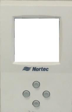
Start Up | 34SETC User Interface
LCD Display and
Input Buttons
(Buttons used to navigate .
status screens and
configure the humidifier,
correspond to icons on
the display)
Status LEDs
Software Drain Button
(Initiates a software
controlled drain)
On/Off Switch
(Turns humidifier On/Off)
Figure 36: Nortec SETC User Interface
Manual Drain Switch
The Nortec SETC/P has a manual drain switch that can drain the tank even if software is not
functioning. To drain the tank put the switch into the drain position. For normal operation the
switch should be in the off position.
Manual
drain
switch
Figure 37: Manual Drain Switch
35 | Start UpStart Up Procedure
1 Examine the humidifier and installation for damage and or improper installation.
Warning: Damaged units or improperly installed units must not be operated. Damaged or
improperly installed units may present a danger to persons and property.
2 Open the supply water shut off valve. If the auxiliary drain valve is installed ensure it is
closed.
3 Slowly open boiler steam isolation valve to allow boiler steam into the steam supply line up
to the CV valve.
4 Turn on the main power using the installed disconnect then turn the On/Off switch on the
front of the humidifier to On.
Request – xx% The LCD display will illuminate and the humidifier will perform
a self-diagnostic sequence during which the LED’s and
Idle 0 lb/hr internal components will be momentarily activated. The
Nortec SE will then begin filling with water. The fill time is
04/30/09 14:25:22
between 10 and 30 minutes depending on the size of the
Security loop: Closed
unit.
Menu
5 Once the water level is close to the top of the tank the LED
lights on the SE’s float chamber will light up and indicate the water level. On start up the
Nortec SE will perform a float and drain pump test by first filling until just the green LED is lit
and then draining until just the red LED is lit. After the float and drain test the humidifier is
in normal operation mode.
Note:
• Pressing the ESC key on the keypad will interrupt the float and drain test and the
humidifier will go straight to normal operating mode.
• If an error is detected during the self-diagnostic sequence a Fault will be displayed.
See troubleshooting section for information on diagnosing and correcting faults.
• Nortec SEP does not have an LCD display. The information on the Nortec SETC’s
LCD depends on the Nortec SETC’s configuration and actual operating conditions.
It may vary from display shown.
6 If On/Off or a control humidistats have been installed check and adjust the control setpoint
on the control and high limit humidistat (see Nortec Digital Controls on page 39). If
transducer controls have been installed then adjust the humidity setpoint using the keypad
and display (see Transducer Control on page 39)
7 When either the external humidistat or internal controller generate a demand for humidity
higher than 15%, the security loop is closed, and the float chamber indicates the tank is full
the SE will transmit a signal to the CV valve to open. Steam will flow into the SE’s heat
exchanger(s) and the SE will heat the water in its tank.
Note: on initial startup with cold water in the Nortec SE’s tank it may take 5 to 15 minutes
(depending on unit size) for the Nortec SE to reach a full boil and produce its rated steam.
Start Up | 368 The green humidifying LED on the front of the humidifier will light up and the display will
indicated “Humidifying” and the amount of steam being produced (Nortec SETC only).
Request – 100%
Idle 750 lb/hr
04/30/09
Security loop: Closed
Menu
Status Screens
In addition to the main status screen the Nortec SETC includes several status screens which
provide additional information about the humidifier. The additional screens can be reached by
pressing the buttons corresponding to the left and right arrow key on the LCD display.
Request – xx% Main Status Screen
This screen reports the current request for humidity, status,
output, date and time, and security loop status. If status is not
Idle 0 lb/hr
04/30/09 14:25:22
idle or humidifying the left arrow key becomes a “?”. If the button
Security loop: Closed corresponding to the arrow key is pressed the display will give
additional information on the status of the humidifier.
Menu
Control Information Screen
CONTROL CONTROL
Output is the lb/hr steam output of
Man Cap. : 100% Man Cap. : 100%
Demand : 55% RH CNT : 55% the unit. Man Cap is the user
Limit : 80% CNT Set-Pt : 50% configured capacity limitation.
Output : 0 lb/hr RH Limit : 100% Depending on the control
LIM Set-Pt : 70% configuration the screen also reports
Output : 0 lb/hr
the current inputs of channel
1 and 2. If the unit is configured for
internal control it also provides the
current humidity and setpoints.
Caution:
• Improper control configuration can result in over humidifying which can result in
damage to property.
• See Advanced Control Configuration if the controls displayed in the control
information screen do not match those connected to the humidifier.
HUMIDIFIER Humidifier Information Screen
Model : SETC 750 Model is the humidifier model type.
Capacity : 750 lb/hr Capacity is maximum output if the unit is supplied 15 psi steam.
Multimode : StandAlone
REG Mode : Demand
Multimode indicates if the humidifier is operating as part of a
Software : XVXX group controlled by a single control signal
Press. In : 15 psi REG Mode is the configured control method.
Software is the installed software version.
Press. In is the boiler steam supply pressure.
37 | Start UpAnalog Output Analog Output Information
Output Signal : X.X VDC Output Signal is the signal currently being output to the actuator.
Capacity : xxx lb/hr Capacity is maximum output based on actual boiler steam press.
Total O/P : xxx lb/hr
Total O/P is the current output of the humidifier.
Tank Monitor : On/Off
Quick Warm : On/Off Tank Monitor indicates if tank monitoring is On/Off.
Press. Base : On/Off Quick Warm indicates if Quick Warm is On/Off.
Press Base indicates if output is based on actual steam pressure.
TANK STATUS Tank Status
Fill Valve : ON/OFF Fill Valve indicates if the fill valve is open or closed.
Drain Pump : ON/OFF Drain pump indicates if the drain is on or off.
Float Level 5 Float level indicates the current float level.
Run Time : xxx hr
Run Time is total weighted operating hours since last service.
Serv. Time : xxx hr
Serv Due : xxx hr Serv Time is the service interval set for the humidifier
Serv Due is the time remaining before service is required.
SENSOR INPUTS Sensor Inputs
Sec. Loop : Closed Sec. Loop indicates if the security loop is open or closed.
Tank Temp. : Closed Tank Temp indicates if the tank is cold (open) or hot (closed)..
FEATURES LIST Features List
Idle Mode : Idle Drain Idle Mode indicates what the humidifier is configured to do when
FTBD : On/Off there is no demand.
Time Prop. : On/Off FTBD indicates if full tank blow down is enabled.
BD Rate : 25%
Drain Cool :On/Off/Smart
BD Rate indicates water drained for scale control as % of output
Float Check : On/Off Drain Cool indicates configuration of drain water cooling feature
Float Check indicates if the humidifier will perform float checks.
FEATURES LIST Operational Hours
Idle Mode : Idle Drain Total indicates the number of hours the humidifier has been
FTBD : On/Off producing steam.
Time Prop. : On/Off
BD Rate : 25% Weighted indicates the total amount of steam the humidifier has
Drain Cool :On/Off/Smart produced expressed as number of hours running at 100% output.
Float Check : On/Off
100% Trend Graph
This graph provides a history of the humidifiers output for the past
4 hours. It displays a percentage of full output which corresponds
to the demand signal. The current demand signal is displayed at
0%
the bottom of the screen.
Start Up | 38Digital Controls
Condair provides optional On/Off, Modulating Control, or Transducer digital controls. Figure 38
and Figure 39 show the function and meaning of the Digital Control’s display and buttons. All
controls are available either wall mounted or with a remote sensor for duct mounting.
Humidity (RH %)
Output signal is shown on
modulating controller
proportional to the demand.
Indicates the
humidistat is on. State of On/Off humidistat
A half moon
indicates it is off.
Snowflake indicates the Setpoint (RH%)
setpoint is being
overridden by outdoor
temperature. Option button accesses
sensor calibration.
See troubleshooting
Power button turns
off the humidiistat if Increase / Decrease Setpoint
pressed for 2 seconds
Figure 38: Modulating and On/Off Digital Control Operation
Modulating Control
The modulating controls use a PI control algorithm to transmit a 0-10V control signal to the
humidifier. Adjust the setpoint to the desired setting by using the up/down arrow buttons on
the controller.
On/Off Control
The On/Off controls use a PI control algorithm to open and close a relay that opens and closes
the humidifier’s On/Off loop. Adjust the setpoint to the desired setting by using the up/down
arrow buttons on the controller.
Transducer Control
The transducer controls transmit a 2-10V control signal proportional to the sensed relative
humidity to the humidifier. Humidity setpoint is not set at the transducer. The setpoint is set on
the Nortec SETC’s display and keypad.
Note: It is possible to field calibrate Condair Digital controls if the displayed humidity is found to
be different than a known trusted source. See Digital Humidistat on page 75 of chapter
on Troubleshooting.
39 | Start UpHumidity (RH %)
Option button accesses
sensor calibration.
See troubleshooting
Adjust calibration
while in calibration
mode
Power button will
display “NO” if an
attempt is made to
turn off the transducer.
Figure 39: Transducer Control Operation
Staged Modulation (Nortec SETC Only)
Start up of each humidifier configured and installed for Staged Modulation is the same as
starting up standalone humidifiers with the exception that for the humidifier to fill and produce
steam the demand to the master unit must be greater than the Multi Unit Op. Range setting of
the unit being started. (Example for a slave unit configured to operate between 20 and 30% the
demand to the master must be greater than 22%)
Each unit connected in a staged modulation system will display its demand as a percentage of
the range for which it is configured. Example, a slave unit configured to operate between 20
and 30% demand will display a demand of 50% when demand to the master is 25%.
Note: See Multi Mode on page 54 and Multi Unit Op. Range on page 56for software
configuration. See Staged Modulation Wiring on page 31 for control wiring of humidifiers
in a Staged Modulation system.
LINKS 2 (Nortec SETC Only)
LINKS 2 is an option that can be integrated with the Nortec SETC. It allows a Building
Management System to monitor and / or control the humidifier. For complete information about
LINKS 2 and its operation and configuration, go to www.condair.com and look up the LINKS 2
manual.
Condair ONLINE (Nortec SETC Only)
Condair ONLINE is an option that can be integrated with the Nortec SETC. It allows a user to
monitor their unit from any computer with an internet connection by logging in to
www.condaironline.com.
It can also be configured to send service reminders and fault warnings when they occur.
Start Up | 40You can also read