NOVA Voyager DVR Drill Press - Teknatool
←
→
Page content transcription
If your browser does not render page correctly, please read the page content below
NOVA

                                      OPERATION MANUAL
Voyager DVR
            ™
Drill Press

                        Publication: 123-0121-019
                        Date: 19. Jan. 2021

                        Models:
                         58000 - USA
                         58001 - NZ/Australia
                         58003 – Europe
                         58006 – Canada
         123-0121-019
                                                         1
CONTACT

New Zealand and Rest of the World
Teknatool International Ltd
Phone: (+64) 9 477 5600
Email: service@teknatool.com
Website: www.teknatool.com

United States
NOVA Innovation and Customer Care Center
Phone: 727-954-3433
Email: service@teknatool.com
Website: http://www.teknatool.com

Or you can contact the retailer where you purchased your NOVA Voyager DVR Drill Press, for the contact details please see our
website www.teknatool.com

                                                         123-0121-019
                                                                                                                                2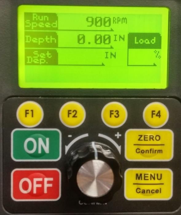
TABLE OF CONTENTS
CONTACT...................................................................................................................................................................................................................................................... 2
TABLE OF CONTENTS.................................................................................................................................................................................................................................... 3
GENERAL SAFETY RULES ............................................................................................................................................................................................................................... 4
ADDITIONAL SAFETY RULES FOR DRILL PRESSES .......................................................................................................................................................................................... 5
INVENTORY .................................................................................................................................................................................................................................................. 6
DVR MOTOR AND CONTROLLER................................................................................................................................................................................................................... 7
Overview ....................................................................................................................................................................................................................................... 7
DVR MOTOR Specifications and Features ...................................................................................................................................................................................... 7
NOVA VOYAGER Specifications and Features ................................................................................................................................................................................ 7
SETTING UP YOUR WORKSHOP .................................................................................................................................................................................................................... 8
Workshop Requirements............................................................................................................................................................................................................... 8
ASSEMBLING THE NOVA VOYAGER DVR DRILL PRESS .................................................................................................................................................................................. 8
Unpacking and Preparing the Drill Press ....................................................................................................................................................................................... 8
Assembling the Column to the Base .............................................................................................................................................................................................. 8
Mounting the Table Bracket and Rack ........................................................................................................................................................................................... 9
Mounting the Headstock ............................................................................................................................................................................................................... 9
Final Assembly Steps ................................................................................................................................................................................................................... 10
Connecting to Power ................................................................................................................................................................................................................... 11
USING THE NOVA VOYAGER DVR DRILL PRESS ........................................................................................................................................................................................... 11
Voyager Operation Basics ............................................................................................................................................................................................................ 12
Mounting and Using the 2MT Keyed Chuck ................................................................................................................................................................................ 15
Positioning the Table ................................................................................................................................................................................................................... 16
Tilting the Table ........................................................................................................................................................................................................................... 16
Quill Lock ..................................................................................................................................................................................................................................... 16
Using the Mechanical Depth Stop ............................................................................................................................................................................................... 16
HMI (HUMAN MACHINE INTERFACE) LAYOUT ........................................................................................................................................................................................... 17
Running the Drill press ................................................................................................................................................................................................................ 17
User Interface Menu ...................................................................................................................................................................................................................... 17
Sensor Guard ............................................................................................................................................................................................................................... 23
Attaching the guard to the drill press .......................................................................................................................................................................................... 24
Adjusting the Sensor Guard ............................................................................................................................................................................................................ 25
Sensor Guard Operation ................................................................................................................................................................................................................. 27
MAINTAINING THE VOYAGER DRILL PRESS ................................................................................................................................................................................................ 27
TEKNATOOL WARRANTY ............................................................................................................................................................................................................................ 29
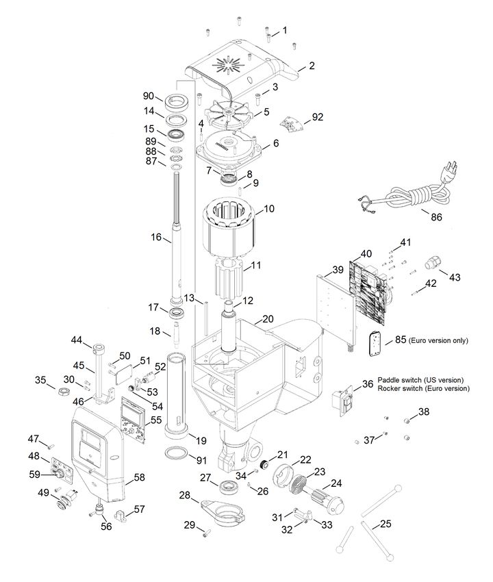
833 Voyager Drill Press Headstock Breakdown .......................................................................................................................................................................................... 30
833 Voyager Drill Press Stand/Table Breakdown ....................................................................................................................................................................................... 31
833 Voyager Drill Press Chuck Guard Breakdown and Parts List ................................................................................................................................................................ 32
833 Voyager Drill Press Parts List ............................................................................................................................................................................................................... 33
833 Voyager Drill Press Wiring Diagram..................................................................................................................................................................................................... 34
© Copyright 2001 -2021 by Tek natool Inter nat iona l; All R ights Reserved.
NOVA is a trademark of Tekna tool Internat iona l Ltd.
DVR is a trademark of DVR Te chnology Developments Ltd.
The inf ormation and spec if ica tions c onta ined herein are su bject to change. Teknato ol is not responsib le for errors or omissi ons
herein or for inc identa l d amages in connect ion with the fur nishing or use of th is in formation.
123-0121-019
3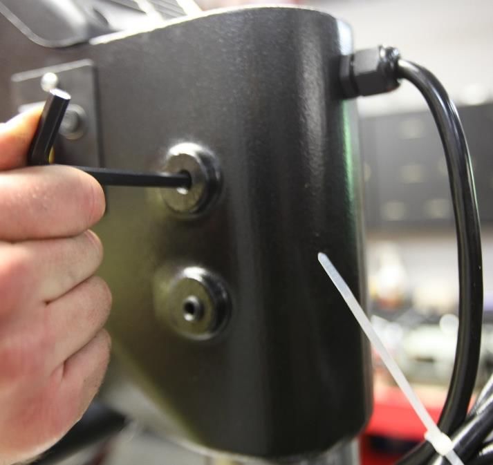
GENERAL SAFETY RULES
                WARNING! Failure to follow these rules may result in serious personal injury or death.
                IMPORTANT: Before switching the drill press on, ALWAYS check the machine for the correct setting and
                speed, as well as ensuring the Chuck Key is removed.

1.    FOR YOUR OWN SAFETY, READ THE MANUAL BEFORE                    14. KEEP GUARDS IN PLACE and in working order.
      OPERATING THE TOOL. Learn the machine’s application            15. USE CORRECT TOOLS. Do not use a tool or attachment to
      and limitations, plus the specific hazards particular to it.         do a job for which it was not designed.
2.    ALWAYS USE A FULL FACE SHIELD-Strongly                         16. USE RECOMMENDED ACCESSORIES. The use of improper
      recommended (must be ANSI approved) Everyday                         accessories may cause hazards.
      eyeglasses usually are only impact resistant and safety        17.   DON’T FORCE THE TOOL. It will do the job better and be
      glasses only protect eyes. A full face shield will protect           safer at the rate for which it was designed.
      the eyes and face. Also use face or dust mask if cutting
                                                                     18.   MAINTAIN TOOLS IN TOP CONDITION. Keep tools sharp
      operation is dusty.
                                                                           and clean for best and safest performance. Follow
3.    WEAR PROPER APPAREL. Do not wear loose clothing,                     instructions for lubricating and changing accessories.
      gloves, neckties, rings, bracelets or other jewelry which
                                                                     19.   NEVER STAND ON TOOL. Serious injury could occur if the
      may get caught in moving parts. Non slip footwear is
                                                                           tool is tipped or if the cutting tool is accidentally
      recommended. Wear protective hair covering to
                                                                           contacted.
      contain long hair.
                                                                     20.   REMOVE ADJUSTING KEYS AND WRENCHES. Form a habit
4.    USE EAR PROTECTORS. Use ear muffs for extended
                                                                           of checking to see that keys and adjusting wrenches are
      period of operation. Use muffs rated to 103 DBA LEQ (8
                                                                           removed from tool before turning it on.
      hour).
                                                                     21.   DON’T OVERREACH. Keep proper footing and balance at
5.    DON’T USE IN DANGEROUS ENVIRONMENT. Don’t use
                                                                           all times.
      power tools in damp or wet locations, or expose them
      to rain. Keep work area well lighted. The NOVA Voyager         22.   DIRECTION OF FEED. Feed work into a blade or cutter
      DVR Drill press is intended for indoor use only. Failure             against the direction of rotation of the blade or cutter
      to do so may void the warranty.                                      only.
6.    KEEP WORK AREA CLEAN. Cluttered areas and benches              23.   PAY ATTENTION TO WORK. Concentrate on your work. If
      invite accidents. Build-up of sawdust is a fire hazard.              you become tired or frustrated, leave it for a while and
                                                                           rest.
7.    KEEP CHILDREN AND VISITORS AWAY. The Nova
      Voyager DVR is not recommended for children and                24.   SECURE WORK. Use clamps or a vice to hold work when
      infirm persons. Such personnel and onlookers should be               practical. Severe injury or death can occur if an object
      kept a safe distance from work area.                                 comes free as it can become a dangerous projectile.
8.    MAKE WORKSHOP CHILDPROOF with locks, master                    25.   CHECK DAMAGED PARTS. Before further use of the tool,
      switches, or by removing starter keys.                               any part that is damaged should be carefully checked to
                                                                           ensure that it will operate properly and perform its
9.    GROUND ALL TOOLS. If the tool is equipped with a
                                                                           intended function. Check for alignment of moving parts,
      three-prong plug, it should be plugged into a three-hole
                                                                           binding of moving parts, mounting, and any other
      electrical receptacle. If an adapter is used to
                                                                           conditions that may affect its operation. Any damaged
      accommodate a two-prong receptacle, the adapter plug
                                                                           part should be properly repaired or replaced.
      must be attached to a known ground. Never remove
      the third prong.                                               26.   DRUGS, ALCOHOL, MEDICATION. Do not operate machine
                                                                           while under the influence of drugs, alcohol, or any
10.   MAKE SURE TOOL IS DISCONNECTED FROM POWER
                                                                           medication.
      SUPPLY while the motor is being mounted, connected,
      or reconnected.                                                27.   DUST WARNING. The dust generated by certain woods
                                                                           and wood products can be harmful to your health. Always
11.   DISCONNECT TOOLS FROM WALL SOCKET before
                                                                           operate machinery in well-ventilated areas and provide
      servicing and when changing accessories such as bits,
                                                                           means for proper dust removal. Use wood dust collection
      cutters and fuses etc.
                                                                           systems whenever possible.
12.   AVOID ACCIDENTAL STARTING. Make sure switch is in
                                                                     28.   DO NOT MODIFY OR USE DRILL PRESS FOR USES OTHER
      the “Off” position before plugging in power cord.
                                                                           THAN FOR WHICH IT WAS DESIGNED.
13.   NEVER LEAVE MACHINE RUNNING UNATTENDED. Do
      not leave machine unless it is turned off and has come
      to a complete stop.

                                                              123-0121-019
                                                                                                                                      4
ADDITIONAL SAFETY RULES FOR DRILL PRESSES
            WARNING! Failure to follow these rules may result in serious personal injury.

1.   SEEK INSTRUCTION. If you are not thoroughly                    12. DO NOT OPERATE DRILL PRESS IF DAMAGED OR FAULTY.
     familiar with the operation of drill press, obtain                 If any part of your drill press is missing, damaged or
     advice from your supervisor, instructor, or other                  broken, in any way, or any electrical component fails, shut
     qualified person. Instruction from a qualified person              off the drill press and disconnect the drill press from the
     is strongly recommended.                                           power supply. Replace missing, damaged, or failed parts
2.   DO NOT OPERATE DRILL PRESS until it is completely                  before resuming operation.
     assembled and installed. Follow instructions and               13. ADDITIONAL SAFETY INFORMATION regarding the safe
     recommendations.                                                   and proper operation of this product is available from the
3.   FOLLOW ELECTRICAL CODES. Make sure wiring                          National Safety Council, 444 N. Michigan Avenue, Chicago,
     codes and recommended electrical connections are                   IL 60611 in the Accident Prevention Manual of Industrial
     followed and that the machine is properly grounded.                Operations and also in the Safety Data Sheets provided by
                                                                        the NSC. Also refer to the American National Standards
4.   WHEN REPLACING THE FUSE (on relevant models),                      Institute ANSI 01.1 Safety Requirements for Woodworking
     completely isolate power when removing the fuse. It                Machines and the U.S Department of Labor OSHA
     is imperative the plug is removed from the power                   1910.213 Regulation.
     supply before the fuse is removed. Replace fuse cap
     before reconnecting to power.
5.   DO NOT OPEN THE SWITCH AND REAR COVERS.
     Components can carry dangerous voltages even
     when isolated from mains power.
6.   KEEP WORK AREA CLEAN. Do not turn the drill press
     on before clearing the drill press of all objects (tools,
     scraps of wood, etc.). Keep the nearby area and floor
     clear of debris.
7.   CHECK SET-UP with spindle off. Examine the set-up
     carefully and rotate the work piece by hand to check
     clearance and check speed is correctly selected
     before turning on spindle.
8.   DO NOT MAKE ADJUSTMENTS when the drill press
     spindle is turning. Make all adjustments with power
     OFF.
9.   TIGHTEN ALL CLAMP HANDLES on the drill press
     before operating drill press.
10. ALWAYS CHECK CORRECT SPEED IS SELECTED
     BEFORE SWITCHING ON DRILL PRESS.
11. OPERATE AT RECOMMENDED SPEED. Always
     operate the drill press at the recommended speeds.
     Consult the built in speed chart on the drill press for
     suggested speeds.

                                                               123-0121-019
                                                                                                                                      5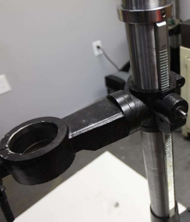
INVENTORY
Use Figure 1 and the inventory list below to inventory your drill press parts:

                         No    SKU                    Description                                Qty
                          1    8338055                Headstock Assembly                          1
                          2    8338028                Column                                      1
                          3    8338025                Base                                        1
                          4    8338046                Table                                       1
                          5    8338054                Table Support Assembly                      1
                          6    8338036                Handle Arm                                  1
                          7    8338032                Lock Handle                                 2
                          8    8338009                Down feed Handle                            3
                          9    AK3, AK4, AK5, AK6     3mm, 4mm, 5mm and 6mm Allen keys            4
                         10    8338037                Handle                                      1
                         11    8338048                17mm/10mm/27mm open and close end wrench    1
                         12    8338049                Chuck drift                                 1
                         13    8338051                Drill Chuck                                 1
                         14    8338052                Chuck Key                                   1
                         15    8338004                Arbor                                       1
                         16    55407                  Firmware Upgrade Cable                      1
                         17*   8338062                Telescopic Chuck Guard                      1

                                                Figure 1 - Voyager Drill press box inventory

Note:

Telescopic chuck guard (shown in figure 1 as #17) is only included in the EU model (58003)

                                                              123-0121-019
                                                                                                       6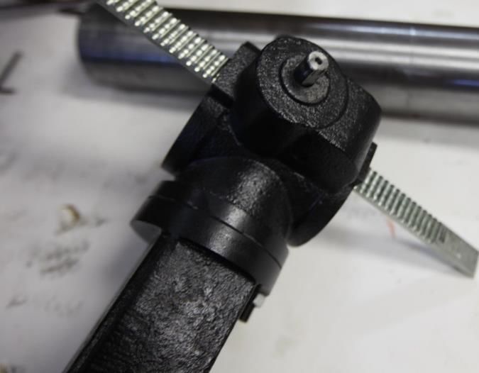
DVR MOTOR AND CONTROLLER
Overview
The DVR Motor drive is a unique type of motor and controller where the motor and controller interact. The motor provides data to
the controller on its position and load conditions. The controller uses this data to handle all the timing and power management to
ensure an energy efficient and powerful motor.
The DVR integrated motor drive system contains four main parts, the DVR Motor (stator and rotor built into the headstock), the Rotor
Position Sensor (RPS), the drive control board and the human-machine interface (HMI). The control board, RPS and HMI make up the
electronic control system of the drive. The control board receives the commands from the user through the keypad and the HMI board,
and it provides useful feedback information to the user such as the running speed and load on the motor. The information is displayed
to the user via the LCD display.

DVR MOTOR Specifications and Features
    •   Type of motor: Switched Reluctance Motor
    •   Rated power output: 1250 W, 1.75 HP
    •   Speed range: 50 – 5500 rpm
    •   Default Speed: 900 rpm
    •   Rotation direction: Bidirectional (FWD & REV)
    •   Power supply range: 115 V – 240 V, 50 Hz – 60 Hz
    •   Power Factor: PF ≥ 0.95
    •   Speed controller: PI speed regulation with adaptive control coefficients
    •   Three pre-set PI coefficient curves: Soft, Normal and Hard
    •   Work piece inertia measurement for PI speed controller adaptive control
    •   Torque and speed ramp functions
    •   Overload protection
    •   Under voltage protection
    •   Control board over-heat protection

NOVA VOYAGER Specifications and Features
    •   Overall Height: 70 5/8” (1794 mm)
    •   Overall Base Width: 17 5/8” (448 mm)
    •   Overall Base Depth: 22 3/4” (578 mm)
    •   Spindle to Table Min Distance: 6 1/8” (155 mm)
    •   Spindle to Table Max Distance: 28 1/2” (724 mm)
    •   Spindle to Base: 48” (1220 mm)
    •   Class F Winding Insulation. Industrial spec for long life
    •   Swing: 18”
    •   Spindle Travel: 6”
    •   Number of Spindle Speeds: Variable
    •   Speed Range: 50-3000rpm is default (option in settings to increase to 5500rpm)
    •   Spindle Taper: MT-2
    •   Table Size (wood working)(L x W): 16 1/2" x 16.1/2” (419mm x 419mm)
    •   Table Tilt (Deg.): -45° to +45°
    •   Table Rotation (Deg.): 360°
    •   Chuck Size: 5/8” (3-16mm)
    •   Column Diameter: 3.62” (92mm)
    •   Base Size (L x W): 22 1/4” x 17 1/2" (565mm x 445mm)

                                                           123-0121-019
                                                                                                                                   7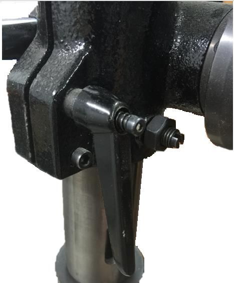
SETTING UP YOUR WORKSHOP
Workshop Requirements

        Consideration               Recommendation
          Drill Press location      Locate the NOVA Voyager DVR Drill Press close to a power source in an area with good
                                    lighting. Leave enough clearance on all sides of the drill press, and be sure to allow for
                                    clearance when the table is swiveled. Other machines in your shop should not interfere
                                    with the operation of the drill press.
                Lighting            Your shop should have adequate lighting. The work area of the drill press should be well
                                    lit; there should not be shadows cast on your work. If possible, locate near a window. A
                                    portable spotlight may be helpful.
               Electrical           The NOVA Voyager DVR Drill Press requires the appropriate power outlet nearby to
                                    power the motor. Wiring and outlets should adhere to local electrical codes. If in doubt,
                                    seek advice from an electrician. Minimize use of extension cords. See "Connecting to
                                    Power" section for extension cord and surge protector requirements.
              Ventilation           Your shop should be adequately ventilated. The degree of ventilation needed will vary
                                    based on the size of the shop and the amount of work done. The use of dust collectors
                                    and filters will minimize risks to your health.

ASSEMBLING THE NOVA VOYAGER DVR DRILL PRESS
                WARNING! Seek help when moving the NOVA Voyager DVR Drill Press and its heavier components to help
                avoid risk of injury. Read and understand the contents of this manual and recommended procedures before
                attempting to assemble or operate the drill press or its parts.
                DO NOT CONNECT POWER ON DRILL PRESS UNTIL FULLY ASSEMBLED.

Unpacking and Preparing the Drill Press
   1.   Open shipping container, remove all components and set aside shipping materials. Keep all materials until drill press is
        assembled and ensured to be operational.
   2.   Arrange all components on the ground to prepare for order of assembly from bottom to top of drill press, making sure to
        use a protective layer to prevent the press from scratches and other damage.

Assembling the Column to the Base
   3.   Place the base in the desired location of the drill press, making sure to put it on a level floor. It can be secured to the floor
        with lag screws (not provided) through the four corner holes in the base.
        NOTE: Do not use a mobile base with this machine.
   4.   Align the column holes with those in the base, and thread the 4 included hex cap bolts onto the base with a 17mm wrench.
        Tighten firmly.

                                                                                                                            17mm
                                                                               27mm                                   7mm

                                                                       •    The 27mm closed end section is for the table support arm bolt.
                                                                       •    The 17mm is for column mounting bolts.
                                                                       •    The 7mm section is for tightening the downfeed handles.

        Figure 2 - The assembled column on the base
                                                             123-0121-019
                                                                                                                                        8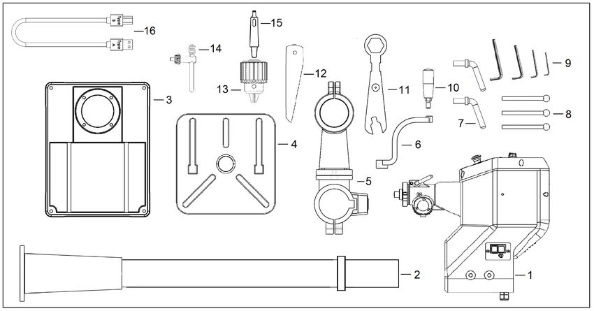
Mounting the Table Bracket and Rack
    5.   Insert the shaft of the worm through the table bracket from the inside as shown below, while mating the worm threads
         with the preinstalled gear. Make sure to insert fully so the maximum shaft is exposed for later steps.
    6.   Insert the rack into the table bracket as shown below, mating the rack teeth with the worm gear. Pay attention to the teeth
         angle with respect to the table bracket orientation. Position the bracket partway on the rack.

                                            Figure 3 - Mounting the table bracket and rack 1/2

    7.   Slide the rack and bracket assembly down over the column and insert the bottom of the rack into the mating groove in the
         sleeve on the bottom of the column.
    8.   Slide the top collar down and over the rack, ensuring that the grooved end of the collar is on the bottom to properly guide
         the rack around the column (see below). Tighten set screw to secure in place.

                                            Figure 4 - Mounting the table bracket and rack 2/2

Mounting the Headstock
      Caution! Be sure to use proper lifting technique to avoid injury or damage to the drill press. Be sure to plan
           the method of attaching the headstock to the column before lifting. Only lift the headstock by the casting to
           avoid damaging more fragile components. Applying lubrication to the column will ease the installation.

                                                             123-0121-019
                                                                                                                                       9
9.   Slide the headstock down over the column, taking care to align the sides of the headstock with the sides of the base.
       Tighten set screws to secure in place.

                                                  Figure 5 - Mounting the headstock

Final Assembly Steps
  10. Attach Table Vertical Adjustment Lever to the lifting mechanism, making sure set screw is fully tightened to flat spot on
      shaft.
  11. Lock the table bracket handle (lock handle behind the column) and insert the table into the table bracket.
  12. Loosen the table release set screw to allow proper locking against table rotation.

                                                       Figure 6 – Table release set screw

  13. Install the 3 handles for raising and lowering the quill assembly.
      Note: Do Not Over Tighten.

                                                           123-0121-019
                                                                                                                                  10
Connecting to Power
WARNING! Improper connection of the motor can result in a risk of electrical shock.
1. The supplied power cord will have a three-prong plug with a grounding prong.
The plug must be plugged into a matching outlet that is properly installed and
grounded in accordance with local electrical codes.
• FOR 115V ONLY: A temporary adapter can be used to plug into a two-
Ground tab
pole outlet if a three-prong outlet is unavailable. The ground tab on the
connected to
adapter must be connected to the screw on the outlet for proper
outlet screw.
grounding. This adaptor should only be used until a qualified electrician
can install a properly grounded outlet.
If it is necessary to use an extension cord, the cord should be grounded and in good
condition. Use an extension cord with a heavy enough gage and to avoid power loss and over-heating, and it is not recommended to
use a long extension cord.
NOTE: Ground Fault Interrupters (GFI's) are generally not compatible with Variable speed motors. If you wish to use a GFI or RCD,
select a unit that is confirmed for use with a Variable speed motor using capacitor charge.
IMPORTANT: A Surge Protection Device must be used, rated to at least 15 amps (for 115V countries, USA and Canada)
or 10 or 15 amps (230V countries). This is to
protect the DVR motors electronics from electrical spikes or surges.
USING THE NOVA VOYAGER DVR DRILL PRESS
Figure 7 - Front view of headstock
123-0121-019
11Voyager Operation Basics
NOTE: For more a more in-depth description on the DVR Drive setup, settings, and features, please refer to section “Running the Drill
Press” in this manual.
When the NOVA Voyager DVR Drill Press has just been powered up, the product name and logo will be displayed on the LCD,
followed by warning messages.
Height Sensor Calibration
The first time the drill press is turned on, the drill press will prompt the user to calibrate the height sensor. To calibrate the sensor,
follow the on-screen prompts and make sure to carefully position the quill height at a consistent spot for each inch interval. If the
consistency of marking each inch isn’t accurate enough, the calibration will have to be redone.
The default home screen will show as follows:
Default Run Speed (Fav. Speed #2D)
Depth displays current vertical position of the quill
Set Depth will display the current User Set Depth (blank when off)
Rev will be displayed at top right only when running in reverse
Load % shows the current load on the motor
Key Description
ON Start key / Reset value in select menus
OFF Stop key / Return to main screen from menu
Menu/Cancel Open menu / Back one level in menu / Cancel
Zero/Confirm Set new zero location / Menu confirm
123-0121-019
12F1 Favorite Speed #1 / Scroll up in menu / Custom function
Favorite Speed #2D / Scroll down in menu / Custom function
F2
Note: #2D is the default start up speed
F3 Favorite Speed #3 / Custom function
F4 Favorite Speed #4 / Custom function
1. GREEN ON – Press to start drill press at the current set speed – always check that the speed has been selected correctly. When
the computer is first switched on it is set at a default speed of #2D (900 rpm by default). Remember that whenever the
computer is switched off at the wall or at the incoming power supply switch, the computer will restart at the default setting. The
spindle cannot restart until “ON” button is depressed.
Ensure that the work piece is secure and the appropriate speed is selected before starting drilling. When the ON button is
pressed, the screen will display the set speed and direction for 2 seconds before switching to the current running speed.
2. RED OFF KEY. Pressing this key will stop spindle rotation and reset the HMI (Human Machine Interface).
The ON / OFF keys in the above panel only switch the motor on and off. The selected speed will remain until adjusted or until
the computer is switched off.
3. RPM KNOB. Rotate the knob clockwise to increase speed and rotate the knob counter-clockwise to decrease speed. The speed
can be adjusted with the drill press running or stopped.
Speed Dial Action Description
Short Press ( Menu Confirm )
Turn Clockwise Increase Speed - Coarse Adjustment / ( Menu Scroll Down )
Turn Counter-Clockwise Decrease Speed - Coarse Adjustment / ( Menu Scroll Up )
Press and Hold In
+ Increase Speed - Fine Adjustment
Turn Clockwise
Press and Hold In
+ Decrease Speed - Fine Adjustment
Turn Counter-Clockwise
The speed is programmed to change with coarse and fine adjustments in increments shown in the following table:
123-0121-019
13Speed Range (rpm) Fine Adjustment Coarse Adjustment
Less than 200 5 rpm 20 rpm
200 – 499 5 rpm 50 rpm
500 – 999 5 rpm 100 rpm
1000 – 2999 10 rpm 200 rpm
3000 and over 20 rpm 500 rpm
4. ZERO/CONFIRM KEY. Pressing this key will set the current drill height as zero, and also will confirm selections in menus or on
screen prompts.
5. MENU/CANCEL KEY. Pressing the Menu key will bring up the user interface menu where the user is able to view and modify
settings on the drill press. For more information on the menu system, see the “User Interface Menu” section. Pressing this key
will also return one level back in the menu.
6. F1 to F4 KEYS. The F1 to F4 keys can be used to set the target speed to favorite speed #1 to #4 respectively. They can also be set
in the menu to perform other functions. Changes to frequently used settings can be made very easily with this feature. This can
be achieved by going to the Menu > Edit F Shortcuts and select the desired function from the list.
Auto safety -- If the power is lost to the machine, when power is restored the computer will reboot but the machine will not start
until the ‘ON’ switch is pressed. Remember to correctly select speed if different from Default speed.
WARNING! Do not push several keys together as special coded combinations of keys open diagnostic and service
functions. Some of these disable control and protection functions. If an unfamiliar screen is displayed, switch off the computer and
leave for one minute before rebooting.
NOTE: If the machine hasn’t been used for some period (over one month) it is helpful to switch the power to the unit on 30 – 60
minutes before use.
123-0121-019
14Mounting and Using the 2MT Keyed Chuck
Figure 8 - Chuck components
1. Before mounting the chuck, be sure to fully clean the 2MT tapered of arbor without lubrication or debris.
Figure 9 - Seating arbor into drill chuck (left) & Seating arbor and chuck into spindle (right)
2. Slide the arbor into the spindle socket while slowly rotating the drill chuck. The Seating arbor into the drill chuck (left)
shown in Figure 9.
3. Insert the arbor and the chuck into the spindle until it stops.
4. If the arbor and the chuck do not fully insert: while applying light upward force, rotate the chuck until it aligns and inserts
fully into the spindle.
5. With the chuck jaws fully retracted, arbor and chuck upward with a hammer on a wood block or a soft hammer to fully seat
the arbor and the chuck. The Seating arbor and chuck into spindle (right) shown in Figure 8.
Caution! DO NOT use a steel hammer on the drill chuck to seat the arbor into the spindle. You will
damage the chuck and/or spindle, which may make them unusable or unsafe.
123-0121-019
15Positioning the Table
The table height and rotational position can be adjusted using the handle on the column:
1. Loosen the locking handle on the rear of the table bracket.
NOTE: It is important to unlock this handle before adjusting the table
2. Rotate the crank handle attached to the rack to raise/lower the table to desired height.
3. Swing the table about the column to the desired position.
4. Retighten the locking handle, and ensure table is securely locked in place before drilling.
Tilting the Table
To tilt the table:
1. Loosen the bolt underneath the table using included 27mm closed end wrench.
2. Loosen set screw underneath the previous bolt using 5mm Allen key.
3. Tilt table to desired angle.
4. Retighten bolt and set screw, and ensure table is securely locked in place before drilling.
Quill Lock
1. To lock the quill at a certain depth, pull the quill lever down to the desired level and turn the quill lock handle clockwise and
tighten firmly.
Figure 10 - Quill lock
2. If the quill lock handle is not fully tightened when it reaches its limit:
a. Pull the handle out along the screw so it freely rotates
b. Rotate back counter-clockwise
c. Set handle fully back down in place on screw
d. Tighten further until snug and quill is locked in place
Using the Mechanical Depth Stop
1. Press the button on the front of the quick release nut to quickly change the height of the nut.
2. For fine adjustment of the height, the nut can be rotated along the threads.
123-0121-019
16HMI (HUMAN MACHINE INTERFACE) LAYOUT
Running the Drill press
Once in idle mode, the LCD will display the information such as the set speed, current run speed, direction and current depth,
depending on the settings.
When the HMI displays that the drill press is ready to run, press the key to start the motor.
The key can be used to stop the motor and reset the HMI into the idle mode.
To set a new zero “Depth” position for the drill press, press the key.
The electronic “Set Depth” can be accessed in the menu to set the drilling depth; press the button to access this “User
Set Depth” setting in the menu and more.
User Interface Menu
The HMI has been programmed with a user interface menu. The menu can be used to configure and view the parameters of the drill
press. The user can access the HMI Menu by pressing the key when the motor is idle or running.
Navigating the Menu
● To cancel or exit the menu, the user can press the key until the HMI returns to the main idle screen.
● To select an item in menu, press the key.
● To move the cursor UP the operator must turn the Speed Dial counter-clockwise OR press the key.
● Similarly, to move the cursor DOWN the operator must turn the Speed Dial clockwise OR press the key.
Menu List
Speed Chart User Set Depth Self-Start Advanced Modes
Edit F Shortcuts Edit Favorite Speeds FWD/REV Configuration
123-0121-019
17Speed Chart
The NOVA Voyager DVR Drill Press includes a built-in speed guide for drilling. The main benefit of the speed chart is the ability to input
the type of drill bit, the drill bit size, and the work piece material, and the drill press will then set the speed to the recommended value.
NOTE: The speed chart is available in both metric and imperial units. This option can be changed in Configuration>Drill Settings.
To use the speed chart:
1. Go to the Menu > Speed Chart.
2. Select the type of drill bit.
3. Select the drill bit size.
4. Select the work piece material.
5. Confirm the new set speed.
6. The display will return to the default screen with the new speed selected.
NOTE: The speed chart is only used to give an approximate of the speed that should be used. The actual drilling speed should be
selected based on the experience of the operator.
User Set Depth
The “User Set Depth” feature allows the user to quickly set the drilling depth. This is essentially an electronic depth stop that will
give warning beeps when approaching the set depth and stop the motor when the depth has been reached.
To activate the User Set Depth feature, simply select the feature in the menu and set a depth to drill. The drilling depth can be set
using the / keys or Speed Dial. Pressing will reset the value to OFF. Press the button to save the
depth selection and return to the main screen, or press to cancel any changes. For blind holes of a certain depth, it is
recommended that the drill bit “Depth” is set to Zero on the surface of the workpiece.
When the “User Set Depth” is activated, the current set depth will show on the main screen. When the feature is disabled, the value
will be blank. When drilling to the set depth, the machine will start beeping at 0.5” (or 10mm in Metric mode), and the beeping will
become more rapid as the drill gets closer to the set depth. The motor will finally turn off once the set depth has been reached and
the machine will revert to idle.
To turn off the “User Set Depth”, press the button followed by the button.
Self-Start
The “Self-Start” feature enables a one-handed drilling operation by automatically turning on and off the motor at pre-determined
start depths. The motor will start running at 0.29”/7mm and stop once it returns to 0.24”/6mm.
For reference, the programming includes the following characteristics:
a. After this feature has been turned on, the handle must be raised to the top of the quill stroke before the first "self-
start" can begin.
b. If the user is in the menu while the machine is idle, the self-start will not START, but it will STOP if the machine is
running with the quill extended, the feature is activated, and the handle is raised to the stop point.
c. By default, the safety feature including warning sounds and a delay before the motor self-starts is turned OFF. This
setting can be accessed through the following menu path: Menu>Configuration>Drill Settings>Sounds/Warnings.
123-0121-019
18Advanced Modes
Pilot Hole
The “Pilot Hole” feature enables the user to skip the separate operation of drilling a pilot hole (in most cases) for locating a larger
drill bit. Using this feature, the machine will begin drilling at a slower speed, and once the bit is seated and grabs enough material,
the machine will sense this and ramp up to the set run speed. The machine determines this by sensing the load placed on the motor
and responding when load threshold (this value is determined by the selected material) has been reached.
To enable the “Pilot Hole” feature, simply toggle “Slow Start” to ON, set the start speed (250 by default), and select
Other/Metal/Wood. Metal will set the load threshold the highest, followed by Wood and then Other requires the smallest increase
in load to ramp up.
IMPORTANT: Once the drill begins running after “Pilot Hole” is turned on, the display will first show “Pilot Initialize” at the bottom
and then change to “Pilot Ready” when fully initialized. Allow the machine to reach the pilot speed and fully initialize before
drilling. If drilling begins prematurely, the load sensing will not calculate correctly, and the drill likely will not ramp up to full speed at
the appropriate time.
Tapping Mode
The tapping feature has two options for programmed cycles for tapping. Both modes require the user to manually feed the tap during
tapping and should only be used when starting the drill in the Forward direction.
1. Load Sense – This mode will use the load sensor to determine when it has started tapping and enter a chip breaking cycle. This cycle
uses the load sensor to determine when the drill needs to switch to reverse to chip break for a fixed amount of time, and then returns
to forward to tap again. This repeats until the drill press senses the tapping is complete via the load OR if the user presses the
button.
NOTE: Recommended for through-hole tapping only.
2. Chip Breaker – This mode will use the load sensor to determine when it has started tapping and enter a chip breaking cycle. This cycle
uses a fixed amount of time before switching to reverse to chip break for a fixed amount of time, and then it returns to forward to tap
again. This repeats until the drill press senses the tapping is complete via the load OR if the user presses the button.
NOTE: The tapping function is recommended for 5/16" (or M8) taps and above. The smaller sized taps may break under high torque
from the motor therefore the user should take care when using the tapping mode on smaller sized taps.
Power Spindle Hold
Power is applied to the DVR motor once this function is activated. This will produce a force which will lock the spindle in place,
allowing to tighten the keyless chuck by hand.
To activate the power spindle hold function (from the home screen):
2. Press
3. Navigate to “Advanced”
4. Navigate to option “Pwr Spindle Hold” and enter function
5. Press to activate the spindle hold function.
NOTE:
The spindle hold function will commence for 30seconds.
It is highly recommended that both hands are used to twist the chuck for final tightening of the chuck to ensure that the drill bit is
held with sufficient force.
Edit F Shortcuts
The to keys can be used to quickly modify a large variety of settings while the motor is idle or running. To set the alternate
functions, go to Menu > Edit F Shortcut. There it will show the current functions for each button. Selecting one of these list items will
open up the list of settings available for each F button. These custom F button functions will be stored permanently in the memory
until a factory reset is performed.
123-0121-019
19Edit Favorite Speeds
The favorite speed function has traditionally been a feature in the DVR motors. The favorite speeds allow the user to quickly switch
between a set of predefined or user defined speeds. The favorite speeds can be accessed by pressing the to keys to select
Fav. Speed #1 to #4 respectively.
The predefined favorite speed values are listed below:
Key Favorite Speed # Speed (rpm)
#1 250
#2D (Default) 900
#3 1600
#4 3000
To modify the preset values follow the steps below:
1. the user can go to Menu > Edit Fav Speeds
2. Select the favorite speed to modify
3. Modify the speed using the / keys or Speed Dial
4. Press to save the new speed
5. Press again to confirm the value and save to memory
NOTE: When confirming the new Favorite Speed value, the new speed is automatically saved to memory. This value will be stored
permanently in the memory until a factory reset.
NOTE: When setting a new Favorite Speed #2D, this changes the default speed of the machine until a factory reset.
Direction: FWD/REV
This menu item strictly toggles the drill rotation direction between Forward and Reverse. The drill must be stopped in order to
change directions.
Configuration
Interface Settings
• Units – Toggles between the units being displayed on the interface
- Imperial decimal
- Imperial fraction
- Metric millimetre
• SET Mode – This allows the user to control the increments when setting the depth for the depth set function.
The table below shows the increments of each modes:
Standard Mode Precision Mode
FINE ± 1mm ± 0.1mm
Metric
COARSE ± 20mm ± 10mm
± 0.05” ± 0.005”
FINE
Imperial ( ± 1/20” ) ( ± 1/200” )
(Decimal) ± 0.5” ± 0.25”
COARSE
( ± 1/2” ) ( ± 1/4” )
Imperial FINE ± 1/16 ” ± 1/64 ”
(Fraction) COARSE ± 1/2 ” ± 1/4 ”
123-0121-019
20IMPORTANT NOTE: The accuracy of the digital read out is heavily dependent on the user calibration process and
how the drill press is used. The precision mode only allows the user to adjust the digital depth stop at smaller
increments. The actual accuracy of the hole drilled is affected by many other factors.
• Fraction Display – This allows the users to select their preferred measuring divisions (When drill press set to
imperial fraction)
- Main division
o Increments of 1/8th, 1/16th, 1/32th, and 1/64th
- Main rounding
- Sub division
o Increments of 1/8th, 1/16th, 1/32th, 1/64th and OFF
- Sub rounding
-
Both the “main” and “sub” display can be set with “Rounding” parameter which simplifies the fraction (e.g. A depth reading
of 12/64th [Rounding OFF] will be display as 3/16th [Rounding ON])
NOTE: If the main display is set in a finer increment than the sub or vice versa, the number displayed will be rounded
towards 0. For example, if the main setting reads 5/32”, the sub display will only display 2/16” (if set to 1/16 increments)
and 1/8” (in 1/8 increments).
• Digital Depth Stop – Toggle between the options of the behaviour of the machine when it reaches the set
depth.
- Do nothing
- Stop motor
- Stop and reverse (2 sec)
- Stop and reverse (6 sec)
- Stop and reverse (to TOP)
• Calibrate Depth – Activates the depth sensor calibration function. Follow on screen instructions to calibrate
• Idle/ Run Display – The rounding option of the numerical value displayed on the LCD screen.
- Speed Rounding: When enabled, this rounds the running speed displayed to the “set speed” if the running speed is
within +/- 10rpm, this reduces the amount of flickering on the screen but can be turned OFF if the user wishes to see
accurate speed feedback
- Load Display: If the user does not wish to see the power output of the motor (load on the machine), this option can be
turned OFF. All load related function will still work if the load display is turned OFF.
- Show Shortcuts: The F button shortcuts at the bottom of the display can be turned OFF for a minimal drill press
interface experience.
• Sound/ Warnings – Option to enable sounds on the HMI for the named action
- Self-start (Default: OFF)
- Set depth (Default: ON)
- Key press (Default: ON)
• Language – Toggle between the languages integrated in the drill press firmware.
- English
- German
- French
123-0121-019
21Motor Performance Settings
To enter the motor performance settings: Menu > Configuration >Motor Performance
• Max Speed – The max speed which the motor will run at (3500rpm, 5000rpm or custom)
Note: Custom speed can set by pressing and holding the speed dial for 3 seconds while the cursor is pointing at the “Max
Speed”
To return to the standard speed limit, the user would simply quick press the speed dial or button.
• Power Output – The amount of power which the motor will exert
1. Low: Predefined power limit of 20%
2. Med: Predefined power limit of 50%
3. High: Predefined power limit of 70%, this is the default value
• Braking – Toggle between braking ON and braking OFF
• Load Sensor - This toggles various settings of the load sensor.
o Jam Detect – This setting detects if the drill bit gets jammed and shuts off the motor. (Default: ON)
o Spike Detect – This detects if the load on the motor spikes abnormally and shuts off the motor. (Default: ON)
o Spike Threshold – This is the load threshold which constitutes a load spike.
• Vibration Sensor – This changes the vibration sensor sensitivity. The vibration sensor will automatically detect vibrations in
the drill press and shut off if the safety threshold has been reached (e.g. if a workpiece has been caught and is spinning
around). There are 4 sensitivity settings: DISABLED / LOW / MEDIUM / HIGH. (Default: Disabled)
Motor Parameters
The DVR motor has built in motor characterizations (speed control profiles), each with slightly different PI controller coefficients and
performance characteristics:
• SOFT - For light drilling. The controller will less aggressively add power to the motor to maintain speed
• NORMAL (default) - Suitable for most work and is the default setting
• HARD - For heavy drilling. The controller will more aggressively add power to the motor to maintain speed.
NOTE: The parameters Kprop and Kint cannot be saved into the EEPROM memory because it is based on the speed profile
parameter.
Parameter Description Default Value
Profile Motor speed control profile Normal
Kprop / Kint PI speed controller coefficients Varies
V kprop / V kint PI voltage controller coefficients 2000 / 9000
Vd DC Bus Motor phase DC bus voltage 360v
T Heatsink Temperature of the controller heatsink -
T Threshold Temperature threshold for current reduction 60ºC
Spd Err Difference between SET and RUN speed -
123-0121-019
22WARNING! Extreme changes to these parameters can result in undesirable and
potentially unsafe motor behavior. Call the NOVA Customer Care Center if you have any
questions on what effects your changes will make.
Set Password
This setting allows the drill press to be locked upon startup, requiring a password to access or run it. If the password is forgotten,
performing a factory reset will clear the password.
Upgrade FW (Firmware)
The HMI plays an important role in the control and functionality of the NOVA Voyager DVR Drill Press, and the HMI firmware version
controls the features and performance of the drill press. The firmware version of the HMI can be upgraded via USB cable accessory
and a PC with internet access. Be sure to check www.teknatool.com periodically for firmware upgrades for your machine, which may
allow new features or software improvements that could enhance the performance of the drill press.
Email service@Teknatool.com for firmware update software and procedure.
Version Info
The current version of the HMI and the main control board can be displayed on the LCD screen.
Factory Reset
If the user is experiencing problems with the NOVA Voyager DVR Drill Press, then it is advised for the user to perform a factory reset.
To perform a factory reset:
1. Press key.
2. Select the Configuration menu item.
3. Select the Factory Reset menu item.
4. Press .
5. Turn off the power to the NOVA Voyager DVR Drill Press. Wait for 5 minutes for the circuitry to completely discharge.
6. Turn the power on and the LCD should display “Warning! – EEPROM Reset”.
7. Turn off the power to the Drill press again and wait 5 minutes.
8. Power up the NOVA Voyager DVR Drill Press again, and the default parameters will be restored to the firmware memory.
Sensor Guard
The NOVA Voyager now comes equipped with a sensor guard which disables the drill press from turning on when the
guard is in the “Open” position.
The sensor guard functionality is included on firmware version R2P05x
Important Note:
The chuck sensor guard will be included in the package only in the EU model (58003). Chuck sensor guard will be sold
separately through all other models (NZ/ AU, Canada and USA). Ask your local NOVA dealers for the purchase of the
sensor chuck guard outside of the EU region.
123-0121-019
23Attaching the guard to the drill press
Guard mounting hardware comes pre-assembled in the package for the EU model.
Remove the top screw (and nut) on the guard.
1.
Slide the guard into the locking boss
2.
Replace the screw and nut removed on (1)
3.
123-0121-019
24Screw the locking knob in to lock the guard into
4. position.
Attach the telescopic guard extension to the
5. guard by using 2 locking knobs included in the
package.
Connect the cable from the chuck guard switch
6. to the connector of the interface panel.
Adjusting the Sensor Guard
Position of the sensor guard can be adjusted vertically to cover a range of different sized chucks and tools.
To adjust the sensor guard height, simply loosen the locking knob on the side to free the plastic guard. Once the guard is
loosened, the vertical position can easily be adjusted by hand. After adjusting the vertical position of the guard, tighten
the locking screw back to lock it into place.
123-0121-019
25Turn the locking knob to release the The guard can be slid up or down when the lock knob is
chuck guard released
Adjusting the telescoping extension
The telescopic extension of the chuck guard can be adjusted prove extra length to the cover chuck guard in order to cover the entire
chuck body.
The extension can easily be adjusted by releasing the knobs located on the side.
Loosen the circled extension lock knobs to release Adjust the chuck guard telescoping extension to the desired length and lock
the extension it into position by tightening the extension lock knob.
Ideal position of the guard:
The guard should always be positioned so it can cover the entire chuck body.
Good Example Bad Example
• The entire chuck body is covered by the • Chuck is exposed from the chuck guard
chuck guard panel therefore posing safety hazards to the
user.
Safety warning
If the guard is not positioned in the correct position, the drill press will always have a potential safety hazard of having
any object flying out towards you or getting anything caught in the moving part of the drill press.
123-0121-019
26Sensor Guard Operation
The sensor guard will stop the motor from running when the guard is opened and it will inhibit the motor from running
until the guard is closed again. If the guard is opened while the motor is running, the motor will stop running and brakes
will be engaged to bring the drill press into a stationary state. The user will not be able to start the motor again until the
guard is returned to the closed position again.
No operation is required on the HMI when the sensor guard is opened. The drill press will automatically detect when the
guard is opened or closed to know when to start and stop the motor.
Chuck guard in the closed position Chuck guard in the open position
MAINTAINING THE VOYAGER DRILL PRESS
WARNING! Always isolate from power supply (unplug) before carrying out any maintenance
Interval Maintenance
After each use Clean the work area and drill press. Vacuum shavings and dust from the headstock,
table, and base.
Monthly Wax exposed cast iron parts with a good quality paste wax. Buff out the wax
thoroughly.
Check tightness of nuts and bolts.
Clean all tapers to ensure a secure fit.
6 Months Lubricate the gear and the rack in the table elevation mechanism and the splines
(grooves) in the spindle with a #2 tube grease.
Lubricate the teeth of the feed shaft assembly and quill shaft with one or two drops of
light-weight oil.
123-0121-019
27TROUBLESHOOTING GUIDE
Problem Possible Cause Solution
1. Work piece is not secure or held tightly 1. Check work piece mounting.
Excessive vibration. enough.
2. Drill press incorrectly bolted to base.
3. Non-stock stand or bench is not well
constructed, too light, or not level on
the floor. Make sure stand is solidly
constructed. Use sandbags to weigh
down the stand.
4. Drill piece is blunt or damaged.
5. Incorrect speed setting.
The optical sensors that give the spindle First, spin the spindle by hand to create a
RP State position feedback (‘Rotor Position’ State) are draught through the sensors. Re-try the motor.
Error obscured, damaged or have been disconnected. If the error remains, with the power switched
Dust over a long period of time may have off and disconnected, remove the upper-rear
settled on the sensors. guard and remove any wood dust with a
vacuum cleaner. Avoid getting the nozzle too
close to the electronics. After this step, dust
may fall into the Headstock, so suck the dust
out through the vent at the front of the
Headstock under the spindle. Do this sequence
a few times. Try blowing if available with
Vacuum or Air gun. Replace guard.
Display screen shows The computer has built in voltage condition and
temperature sensors. If this message appears,
PFC check the temperature of the lower section of
Corrector the headstock. If it is very hot, switch off the
master switch and leave the machine to cool
down for a period. If the headstock is relatively
cool, the computer may have detected an
under and over voltage from the mains power.
Switch off and try rebooting. The DVR has a
high level of protection and is intelligently
checking conditions all the time.
123-0121-019
28You can also read