Wireless, battery-free, and fully implantable electrical neurostimulation in freely moving rodents - Nature
←
→
Page content transcription
If your browser does not render page correctly, please read the page content below
Burton et al. Microsystems & Nanoengineering (2021)7:62
                                    https://doi.org/10.1038/s41378-021-00294-7
                                                                                                                                                               Microsystems & Nanoengineering
                                                                                                                                                                                                www.nature.com/micronano

                                     ARTICLE                                                                                                                                                    Open Access

                                    Wireless, battery-free, and fully implantable
                                    electrical neurostimulation in freely moving
                                    rodents
                                    Alex Burton1, Sang Min Won 2, Arian Kolahi Sohrabi3, Tucker Stuart1, Amir Amirhossein1, Jong Uk Kim4,
                                    Yoonseok Park 4, Andrew Gabros3, John A. Rogers 4,5,6,7,8,9 ✉, Flavia Vitale10 ✉, Andrew G. Richardson 3 ✉ and
                                    Philipp Gutruf 1,11,12 ✉

                                      Abstract
                                      Implantable deep brain stimulation (DBS) systems are utilized for clinical treatment of diseases such as Parkinson’s
                                      disease and chronic pain. However, long-term efficacy of DBS is limited, and chronic neuroplastic changes and
                                      associated therapeutic mechanisms are not well understood. Fundamental and mechanistic investigation, typically
                                      accomplished in small animal models, is difficult because of the need for chronic stimulators that currently require
                                      either frequent handling of test subjects to charge battery-powered systems or specialized setups to manage tethers
                                      that restrict experimental paradigms and compromise insight. To overcome these challenges, we demonstrate a fully
                                      implantable, wireless, battery-free platform that allows for chronic DBS in rodents with the capability to control
                                      stimulation parameters digitally in real time. The devices are able to provide stimulation over a wide range of
                  1234567890():,;
1234567890():,;
                  1234567890():,;
1234567890():,;

                                      frequencies with biphasic pulses and constant voltage control via low-impedance, surface-engineered platinum
                                      electrodes. The devices utilize off-the-shelf components and feature the ability to customize electrodes to enable
                                      broad utility and rapid dissemination. Efficacy of the system is demonstrated with a readout of stimulation-evoked
                                      neural activity in vivo and chronic stimulation of the medial forebrain bundle in freely moving rats to evoke
                                      characteristic head motion for over 36 days.

                                    Introduction                                                                                        and, more importantly, removes the need for tethers to
                                      Wireless battery-free investigative tools for targeted                                            enable experiments in naturalistic environments3. Recent
                                    neurostimulation of the brain have become important to                                              examples include the first demonstration of neuromodu-
                                    expand neuromodulation to freely moving small animal                                                lation in freely flying birds6 and in multiple socially
                                    subjects1–5. Continuous wireless power transfer (WPT) to                                            behaving rodents4, both of which would be difficult or
                                    the implants enables ultrathin platforms that are fully                                             impossible to achieve with standard tethered approaches.
                                    subdermally implantable, which reduces infection risk                                               These current demonstrations utilize optogenetic stimu-
                                                                                                                                        lation, which is a powerful tool for exploratory research
                                                                                                                                        because of cell-type-specific modulation capabilities and
                                    Correspondence: John A. Rogers (jrogers@northwestern.edu) or                                        minimal electronic hardware requirements, which enable
                                    Flavia Vitale (vitalef@pennmedicine.upenn.edu) or                                                   subdermal embodiments that are scalable and feature
                                    Andrew G. Richardson (Andrew.Richardson@pennmedicine.upenn.edu) or
                                                                                                                                        small footprints. While optogenetics informs translational
                                    Philipp Gutruf (pgutruf@arizona.edu)
                                    1
                                     Department of Biomedical Engineering, University of Arizona, Tucson, AZ                            approaches7, direct translation is difficult because of the
                                    85721, USA
                                    2
                                                                                                                                        lack of opsin expression in human subjects.
                                     Department of Electrical and Computer Engineering, Sungkyunkwan
                                                                                                                                          Current clinical neuromodulation therapies, such as
                                    University (SKKU), Suwon 16419, Republic of Korea
                                    Full list of author information is available at the end of the article                              deep brain stimulation (DBS) for movement disorders,
                                    These authors contributed equally: Alex Burton, Sang Min Won

                                    © The Author(s) 2021, corrected publication 2021
                                                        Open Access This article is licensed under a Creative Commons Attribution 4.0 International License, which permits use, sharing, adaptation, distribution and reproduction
                                                        in any medium or format, as long as you give appropriate credit to the original author(s) and the source, provide a link to the Creative Commons license, and indicate if
                                    changes were made. The images or other third party material in this article are included in the article’s Creative Commons license, unless indicated otherwise in a credit line to the material. If
                                    material is not included in the article’s Creative Commons license and your intended use is not permitted by statutory regulation or exceeds the permitted use, you will need to obtain
                                    permission directly from the copyright holder. To view a copy of this license, visit http://creativecommons.org/licenses/by/4.0/.
Burton et al. Microsystems & Nanoengineering (2021)7:62                                                                                 Page 2 of 12

                   a                                                                                       b
                                         Copper                                          PI
                    Components

                                                                   Pt                               PI
                             Polyimide                                        Au

                         Copper                   Probe                        W
                                                                                                                               5 mm

                   c                  Red LED                                       Magnetic
                         Electrode              Control                             Resonant
                                                           LDO
                                                                                    Coupling

                                                                  13.56 MHz

                                                                                    13.56 MHz
                                                                                     Antenna
                                                                   Antenna
                                                µC
                                                                                                 RF
                                                                                                power
                        Electrode
                       Brain tissue             Timing         Energy                             Power
                        stimulation        and control      harvesting                           supply                       300 μm

                   d                                                                                       e        Rostral
                   Program                                                                      RF tuner                      Screws
                    device

                     RF
                    power                                              Antenna
                                                                                   Rat                     Device
                    Pulse
                    train
                                                                                                            5 mm              Caudal

 Fig. 1 Device overview and summary of operation. a Exploded view illustration of the brain stimulation device (left) and electrode inset.
 b Photograph of the wireless brain stimulation device with an inset of a micrograph of the probe tip. c Block diagram of circuit function. d Mode of
 operation during experimental paradigms used in this work. e 3D µCT reconstruction of the implanted device in a rat

utilize electrical stimulation. A key challenge in DBS is                            these issues. However, technological hurdles have, up to
identifying appropriate stimulus parameters and dosing8,                             this point, prohibited such a device due to requirements
resulting in up to 50% of DBS patients experiencing side                             for pulse timing, voltage and current modulation, and
effects9. The need for parameter optimization and                                    biphasic stimulation, which are not easily realized in small
mechanistic insight into DBS therapies motivates the                                 footprints with commercial components that enable
demand for chronic electrical stimulation tools for small                            scalable fabrication and rapid dissemination. In this work,
animal models such as rodents. In addition to DBS,                                   we present devices that overcome these current techno-
chronic electrical stimulation is integral to emerging                               logical challenges by using digitally addressable stimula-
sensory neuroprostheses that restore sight, hearing, and                             tors that utilize off-the-shelf components with ultrasmall
the sense of touch after neurological injury or disease10.                           footprints that leverage highly optimized antenna designs
The full stimulus parameter space is rarely explored in                              and custom one-way communication protocols to enable
neuroprosthetic studies, increasing the reliance on                                  subdermally implantable wireless, battery-free neuromo-
unnatural evoked sensations. With technologies that                                  dulators with real-time voltage-controlled biphasic sti-
enable electrical stimulation in freely behaving rodent                              mulation capabilities.
models, artificial sensory encoding paradigms could be
optimized11.                                                                         Results
  Current battery powered and tethered methods for                                   Wireless DBS device
chronic stimulation in rodent models complicate studies.                               A monolithic design incorporates WPT capabilities in a
Due to the bulky nature of batteries that require frequent                           thin flexible form factor that enables full subdermal
charging between experiments and tethered approaches                                 implantation of the DBS, as shown in Fig. 1a. The flexible
requiring animal care and constant interaction with test                             serpentine structure that connects the device body and
subjects to prevent entanglement12, results in current                               the injectable stimulation probe allows for easy manip-
techniques impacting subject behaviors1. A wireless,                                 ulation of the probe during surgical procedures and
battery-free and fully implantable device would alleviate                            provides an interface that facilitates custom probe designs
Burton et al. Microsystems & Nanoengineering (2021)7:62                                                       Page 3 of 12

(Fig. 1b and Fig. S1a–c) to control impedance, depth, and      Fig. 2c. The direct use of µC IO enables high-frequency
spacing of the electrode13,14. The circuit utilizes magnetic   stimulation pulses up to 20 µs and a frequency of 50 kHz.
resonant coupling at 13.56 MHz for WPT by tuning the           Figure 2d shows corresponding current and voltage traces
device antenna with matching impedances to the oper-           with an electrode impedance of 10 Ωk at 1 kHz. Current
ating frequency of the primary antenna, which in turn also     and voltage output is stable under a wide range of loads,
operates in resonance4,6,15–19. The harvesting circuit uses    as shown in Fig. 2e. To minimize footprint, an input
a half-bridge rectifier with a Zener diode for overvoltage      voltage adjustment to the µC is used to control stimula-
protection. An adjustable low-dropout (LDO) regulator          tion amplitudes. The resulting circuit footprint (20 mm2)
controls the input voltage to the microcontroller (µC),        is >10x smaller than that of other wireless electrical sti-
which utilizes a feedback loop to adjust the stimulation       mulation tools28 and enables designs to be adapted to a
voltage. Biphasic stimulation is delivered by controlling      variety of animal models4. The voltage amplitude
the tri-state (High, Low, High Impedance) of the μC            (1.5–5.5 V) of the biphasic stimulation is controlled
input-output (IO) pins. Stimulation voltage is controlled      through an analog feedback loop (Fig. 2f) through the
by regulating the operation voltage of the digital system by   adjustable LDO, which is optimized to control the µC
changing LDO output voltage, as schematically shown in         input voltage within the voltage range of the µC supply
Fig. 1c. This method of biphasic stimulation allows charge     with up to 12 bits of resolution, as shown in Fig. 2g and
balancing of the electrode, improving stimulation              Fig. S3b. Finite element simulations of the field potential
responses20,21 and minimizing tissue damage and corro-         and current density of the electrode design with 1 mm
sion of the electrodes during chronic stimulation22,23.        spacing are shown in Fig. 2h. The results enable estima-
  Stimulation parameters are wirelessly transmitted using      tion of effective stimulation radius29,30, which, with
a custom protocol that is compatible with commercially         biphasic pulses of 5 V, elicits a response up to ~2.3 mm
available power casting systems and features 18 bits to        from the electrode sites (Fig. S3c) when considering a
control amplitude, pulse width, period, and duration by        current density stimulation threshold of >0.97 mA/cm2 31.
modulating the radio frequency (RF) power, as shown in
Fig. 1d and Fig. S2a–c. Storing these values in electrically   Wireless operation and mechanical properties
erasable programmable read-only memory (EEPROM)                  Figure 3a shows the dimensional optimization of the
allows a recall of up to 256 of these parameter spaces. The    secondary antenna that allows mounting of the device on
thin and flexible nature of the device allows conformal         the adult rat skull while maximizing its power harvesting
adhesion to the skull, allowing seamless recovery of the       capabilities. The secondary antenna utilizes a 6-turn dual-
subject after implantation. The device is operational in       layer design (70 µm trace width, 70 µm trace space) that
both magnetic resonance imaging (MRI) and micro-               optimizes power delivery while minimizing the secondary
computed tomography (µCT) systems because of careful           antenna cross-sectional dimensions (500 µm × 190 µm) to
component selection that features ferromagnetic-free           result in the smallest possible device footprint with a
materials4,17. This capability allows the rapid validation     weight of only 46 mg, which enables faster recovery and
of probe and device placement postsurgery, as shown in         easier implantation. For our experimental paradigm, the
Fig. 1e, as well as capabilities to expand experimental        device is powered in a two-turn primary antenna oper-
paradigms to stimulate electrically while imaging with         ating at 13.56 MHz, circumferentially attached to a
µCT and MRI16.                                                 28 cm × 22 cm cage at heights of 4 and 8 cm, as shown in
                                                               Fig. 3b. Experimental paradigms are not limited to this
Electrode and stimulation control                              antenna configuration. Characterization of harvesting
  The probe is comprised of multiple thin layers, with a       capabilities of the device in several experimental arenas
cross-sectional dimension of 220 µm × 200 µm (Fig. 2a), to     important for both behavioral32 and therapeutic33 studies
minimize tissue damage during insertion while main-            are shown in Fig. S4a–d and indicate ample harvested
taining mechanical support to increase targeting accuracy,     power for device operation in these experimental enclo-
improve stimulation efficacy, and ensure repeatability of       sures. Commercial power casting systems with the ability
experiments17,24,25. Monolithic fabrication of the probe       to provide up to 12 W of RF power (Neurolux Inc.) and
allows various electrode designs and the study of specific      the capability to interface with additional peripheral
neural pathways26,27. The impedance of the probe is            hardware such as levers and buttons to control stimula-
controlled with an engineered high surface roughness of        tion delivery can be used for closed-loop control during
±400 nm (Fig. S3a) of the platinum electrode material, as      behavioral experiments that study empathy, attention,
shown in the scanning electron microscopy (SEM) image          feeding, and addiction34–37. The secondary antenna
in Fig. 2b. Impedance characteristics of the electrode         design of the fully implantable device is optimized to
are tested before implantation to determine the voltage        harvest peak power (18 mW) at 5.5 V in the center of a
range needed to elicit neural activation, as shown in          28 cm × 22 cm cage, as shown in Fig. 3c, when powered
Burton et al. Microsystems & Nanoengineering (2021)7:62 Page 4 of 12
a Polyimide b
Platinum
Gold
Polyimide Electrode surface
Front PDMS
Polyimide
Back Tungsten
Cyanoacrylate glue 250 μm 5 μm
c 300 80 d 6 0.8 e 2
3k
4.7k
Impedance (kΩ)
60 3 0.4 1
Current (mA)
100
Current (mA)
Voltage (V)
Phase (θ)
8.2k
40 15k
0 0 0
22k
33k
20 –3 –0.4 –1
10
6 0 –6 –0.8 –2
10 2 10 3 10 4 10 5 0 50 100 0 0.25 0.5 0.75 1
Frequency (Hz) Time (μs) Time (ms)
f g 5.5 h Front Side
Vin 5 5
μC
Current density (mA/cm2)
Output votlage (V)
LDO 4.5
Vout 4 4
Field potential (V)
6.6 µF
2.2 μF GPIO 3.5 3 3
150 k
FB 2.5 2 2
15.3 k 3.2 k
1M 1 1
1.5
0 1024 2048 3072 4096 0 0
2.2 μF DAC value (a.u.) 500 μm 1 mm
Fig. 2 Electrode design and characterization of stimulation. a Layered construction of the stimulation probe with a photograph inset showing
the front and back side. b SEM image of the probe with a magnified inset of the electrode pad. c Electrode impedance spectra in PBS. d Stimulation
speed demonstration with sub-microsecond resolution. e Constant-voltage stimulation under varying loads. f Block diagram of the circuit used to
control voltage. g Twelve-bit control over voltage used for stimulation. h Simulation of field potentials and current density generated at the probe tip
with 3 W of RF power. This harvesting ability is sig- misalignment of the device position and angle with
nificantly greater than previous WPT designs that have respect to the cage antenna indicates stable operation of
been demonstrated with more RF input power and the device during various naturalistic motions, such as
smaller experimental arenas4,15,16. The device consumes rearing38. To accommodate these behaviors of the animal,
an average of 9.35 mW during stimulation epochs with a the device requires a minimum safety margin of 1.2,
peak consumption of 29 mW for 0.6 ms during 5 V sti- which is measured relative to the lowest power availability
mulation, as shown in Fig. 3d. Lower average power within the cage4. This device provides a safety margin of
consumption is achieved by optimizing the µC firmware ~2, enabling stable operation in a wide variety of condi-
with a 1 MHz clock speed and sleep events that suspend tions. Cage powers can be adjusted and feature a linear
peripheral components of the digital system. Three- correlation of harvested power, as shown in Fig. 3g,
dimensional mapping of power is performed at heights measured in the center of a 28 cm × 22 cm cage. This
of 5 cm and 10 cm in a 28 cm × 22 cm cage with 3 W of RF characterization can be used to estimate the power need
power, as shown in Fig. 3e, indicating sufficient power for larger experimental enclosures. This is demonstrated
throughout the experimental arena to drive stimulation. by operation in increasing cage dimensions (10–20 cm,
The effects of angular misalignments is also investigated radius) (Fig. 3h). Using a safety margin of 1.2 to provide
in the center of the 28 cm × 22 cm cage with 3 W of RF continuous device operation, RF power requirements are
power, as shown in Fig. 3f, indicating a linear reduction in calculated for various cage areas, as shown in Fig. 3i,
harvesting capabilities when the device is rotated relative resulting in a maximum arena size of 999 cm2 with 10 W
to the primary antenna. Harvesting capabilities during of RF power.Burton et al. Microsystems & Nanoengineering (2021)7:62 Page 5 of 12
a b c 20 25
20
15
Power (mW)
15
Voltage (V)
10
10
Voltage
5 Power 5
0 0
0 10 20 30
Ω)
Resistance (kΩ
d 6 e mW f 18
Stim 55
10
Harvested power (mW)
5 50
Current (mA)
Height (mm)
45 12
8
4 Sleep Sleep
40
3 6 35 6
30
2 4
0 25
20 0
10
0 2 4 6 8 10 20 10 20 0 15 30 45 60 75
0
Time (ms) Length (cm) Width (cm) Device angle (deg.)
g 70
h 103
i 18
10 cm
Harvested power (mW)
Harvested power (mW)
60 15
Required power (W)
50 2
12.5 cm
10 12
40
15 cm 9
30
101 17.5 cm 6
20
20 cm
10 3
0 100 0
2 3 4 5 6 7 8 9 10 0 4 8 12 16 300 550 800 1050 1300
Cage power (W) 2
Cage power (W) Area (cm )
°C Deformation (cm)
j Top 37.0
k 0 1 2
l 160 148+ 148+
Max 0.8
37.0 °C
36.8
0.6 120
Lifetime (days)
36.6
Stress (N)
79
0.4 80
36.4
0.2
40
36.2
0
Bottom 0 25 50 75 100 125 150
Max 0
36.8 °C 36.0 Strain (%) 43°C 60°C 90°C
Fig. 3 Power harvesting, thermal, and mechanical testing of the device. a Photograph of the device mounted on a dimensionally accurate 3D
printed adult rat skull. b Photograph of the experimental arena used for in vivo stimulation studies. c Harvesting power vs. load curve in the center of the
arena (22 cm × 28 cm) with RF input power of 3 W. d Current consumption during operation of the device during a single stimulation pulse. e Spatially
resolved energy harvesting capability at two heights of the miniaturized device in a cage with dimensions of 22 cm × 28 cm and 3 W RF input. f Harvested
power vs. angular misalignment between the device and cage antenna in the center of the arena (22 cm×28 cm) with RF input power of 3 W. g Power
harvested between RF powers of 2 W and 10 W. h Power harvested in the center of two turn circular cages with increasing cage radius. i RF power needed
for stable operation with a 20% safety factor in two turn circular cages with increasing cage radius. j Steady-state thermal impact simulation of device under
continuous operation in saline. k Mechanical characteristics of serpentine interconnect. l Accelerated rate testing of device encapsulation in PBS
Steady-state simulations of device heating resulting (PBS) solution (36 °C) under natural convective heat
from thermal losses of active and passive components in transfer during continuous operation (>500 s). The results
the circuit are investigated in a phosphate-buffered saline shown in Fig. 3j indicate a maximum increase in deviceBurton et al. Microsystems & Nanoengineering (2021)7:62 Page 6 of 12 temperature of
Burton et al. Microsystems & Nanoengineering (2021)7:62                                                                                                               Page 7 of 12

                        a                                                      c                               150
                              Sensing electrode

                                                                                   Stim-triggered Avg. (μV)
                                                                                                               100

                                                                                                                50

                                                        vM1                                                      0

                                                       vS1                                                     –50

                                                                                                              –100

                             Stimulating electrode
                                                                                                              –150
                            (3.3 V × 0.2 ms, N = 289)
                                                                                                                  –0.2      0      0.2       0.4    0.6   0.8
                                                                                                                           Time from stimulus (s)

                        b
                             vS1 stim
                                                        Superficial
                                Laminar vM1 activity

                                                        Deep
                                                                1 mV

                                                                       0.5 s

 Fig. 4 Stimulation and recording of neurological responses. a Illustration of acute experiment showing the location of wireless stimulation site
 (vibrissal primary somatosensory cortex, vS1) and wired recording site (ipsilateral vibrissal primary motor cortex, vM1) with a segment of vM1
 recording during 1-Hz vS1 wireless stimulation (indicated by red vertical lines). b Segment of vM1 recording during 1-Hz vS1 wireless stimulation
 (indicated by red vertical lines). c Stimulus-triggered average of neural activity recorded on each of the vM1 laminar probe channels. In both graphs b
 and c, the two most superficial recordings from the 16-channel array were omitted

experimental paradigms. The small size and minimal                                                                       and battery-free operation for features such as neural
footprint of the implants and the use of ferromagnetic-                                                                  recording and muscle interfaces46.
free off-the-shelf components enable compatibility with
noninvasive 3D imaging of subjects and facilitate the                                                                    Materials and methods
possibility of broad dissemination with existing scaled                                                                  Flexible circuit fabrication
manufacturing technologies. Successful chronic                                                                             Copper traces were defined on Pyralux (AP8535R; con-
experiments and scalable technologies demonstrated in                                                                    stituent layers: 17.5-µm copper, 75-µm polyimide, and
this work suggest potential for widespread adoption in                                                                   17.5-µm copper) using a UV (355-nm) laser ablation sys-
neuroscience research and will enable future studies to                                                                  tem (LPKF; Protolaser U4). The flexible circuits were
explore chronic electrode performance, stimulation-                                                                      cleaned in stainless steel flux (Superior Flux and Manu-
induced neural plasticity, and chronic closed-loop                                                                       facturing Company; Superior #71) for 2 minin an ultra-
behavioral studies in freely moving subjects. The tech-                                                                  sonic cleaner (Vevor; Commercial Ultrasonic Cleaner 2 L)
nology may also serve as a platform to enable wireless                                                                   and rinsed with deionized (DI) water. Via connections
Burton et al. Microsystems & Nanoengineering (2021)7:62 Page 8 of 12
a b c
OFF ON
Day 9 Day 15 Day 21
Post surgery
A
d Control e Hedges’ g = 0.16 f Head speed
12
Linear speed (pixels/s × 102)
8
21 days
4
0
29 days
Implanted Control Implanted
6 Hedges’ g = 0.05
Angular speed (deg/s × 103)
36 days
4 200 pixels/s
2 No
Stim
0 1 2 3 0 –0.5 0 0.5 1 1.5 2
Head speed (log10(pixels/s)) Control Implanted Relative time to stimulus onset (s)
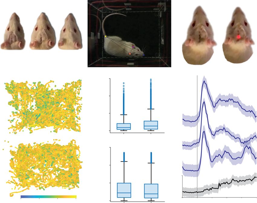
Fig. 5 Recovery and behavior of freely moving animals. a Images documenting healing of the scalp over the implant. b Example image from
overhead video used to quantify the rat’s response to wireless stimulation of the MFB. Superimposed colored circles show the pose estimates of the
deep learning model used to track movement for the nose, ears, and tail base. c Implanted device LED visible through the scalp on a video frame
immediately before stimulation (left) and at stimulation onset (right). d Tracked head position within the open field for a control rat and the
implanted rat (from 4 × 10 min sessions each). Colors of datapoints at each position indicate head speed. e Distribution of linear (top) and angular
(bottom) head speeds for the control and implanted rats. f Mean head speed (±95% CIM) relative to stimulus onset in three testing sessions (blue
traces) and relative to random times when animal was at rest in a no-stimulation control session (gray trace)
were established manually with copper wire (25 µm) and with a 3.3 kΩ current limiting resistor, controlled timing
low-temperature solder (Chip Quik; TS391LT). Combi- of electrical stimulation, and LDO output voltage. The
nations of 0201 capacitors (108 pF) were used to tune the components were reflowed with a hot air gun at 350 °C
power harvesting antenna. A half-bridge rectifier was built using a low-temperature solder (Chip Quik; TS391LT).
with low-capacitance Schottky diodes (Skyworks) and The devices were tested with a reflection bridge (Siglent;
three 0201 capacitors (2.2 µF). A Zener diode (Comchip SSA 3032X; RB3X20), and additional tuning capacitors
Technology Corporation; 5.6 V) provided overvoltage were added to provide the lowest-voltage standing wave
protection to limit the supply voltage to the adjustable ratio at 13.56 MHz. Silver particle-filled epoxy (Model
LDO (Maxim Integrated, MAX38902C) used to stabilize 8331, MG Chemicals Inc.) was used to establish an elec-
the input voltage to the µC (Atmel; ATtiny 84 A). A cus- trical connection to the probe and cured at 65 °C for
tom programmer board using Arduino as ISP was used to 30 min. The connection was mechanically joined using UV
program the µC before mounting on the circuit. The µC curable glue (Damn Good; 20910DGFL) and cured under
provided control over visual indication through a red LED a UV lamp (24 W, 10 min). A tungsten foil (Alfa Aesar,Burton et al. Microsystems & Nanoengineering (2021)7:62 Page 9 of 12
CAS# 7440-33-7) was defined through laser ablation Encapsulation
(LPKF; Protolaser U4) and mounted to the back of the The devices were rinsed with IPA for 10 min and air-
probe using cyanoacrylate as a structural support.” dried. UV curable glue (Damn Good; 20910DGFL) was
added over the components, then cured under a UV lamp
Stimulation electrode fabrication (24 W, 10 min) and degassed in an oven (100 °C, 5 min) to
Figure S7 presents a schematic illustration of the fabrica- add mechanical protection to the solder interface of the
tion and layout of the stimulation electrode. The first step surface-mounted components. The conformal coating
involves the removal of the copper layer from a flexible was achieved by Parylene-C encapsulation: the electrode
copper-clad polyimide film (AP9111R, DuPont), yielding a tip was covered with polyimide sheets on either side of the
25 µm thick polyimide with a surface roughness of ±400 nm. probe to protect the electrode surface from the coating,
This substrate served as a template to introduce the surface and the seams were held together using parafilm. The
roughness on subsequent thin-film metal layers. A photo- devices were suspended along a wire and encapsulated
lithography and lift-off process, followed by electron beam using the Parylene P6 coating system (Diener electronic
evaporation (Cr/Au/Ti/Pt, 5/100/5/100 nm), defined both GmbH, Germany) with 2 coating runs each using 5.0 g of
the stimulating metal electrode and the interconnects. A Parylene-C dimer for a total thickness of ~18 µm, cover-
coating of polyimide (PI2545, HD MicroSystems; 2 µm in ing the entire device surface conformally with Parylene-C
thickness) served as the passivation layer, opened the contact to provide a moisture barrier and a biocompatible bioin-
pad by reactive ion etching (O2, 100 mTorr, 100 W, terface. The encapsulation thickness was calculated from
20 sccm, 10 min) and exposed the platinum (area of measurements using a profilometer (Tencor P15, KLA)
130 µm × 130 µm) stimulation electrode. A 75 µm thick and subsequently controlled using Parylene-C dimer
polyimide film served as the supporting substrate for short weights (Fig. S8). Polyurethane-coated devices were
electrodes (below 4 mm), and the addition of a tungsten obtained by covering the probe tips, hanging the devices
shuttle (50 µm thickness) served as a stiffener to enable on a wire, spraying them with premium polyurethane
high-accuracy targeting. Both supporting substrates were conformal coating (4223 F, MG Chemicals Inc.), and
attached to the electrode film with an adhesive layer (poly- curing at 90 °C for at least 12 h. The devices were finally
dimethylsiloxane). The laser cutting process (ProtoLaser U4, dip coated with PDMS (SYLGARD™ 184 Silicone Elas-
LPKF) completed the formation of the electrode layout. tomer kit) and cured at 80 °C for 10 min after the excess
was removed using a syringe.
Electrode characterization
The electrical behavior of the microelectrodes was Power harvesting characteristics
studied in Dulbecco’s PBS solution (14190-136, Gibco, Voltage and power harvesting characteristics were
Life Technologies). A three-electrode electrochemical cell collected (Aneng; AN8008) using a load resistor in the
including a stimulating electrode, Pt wire, and Ag/AgCl center of a 28 cm × 22 cm arena powered with a dual
electrode (MF-2052, BAS) as the working, counter, and loop antenna with 3 W of RF power. A shunt resistor
reference electrodes, respectively, was immersed in PBS. (1.6 kΩ) was used to match the system load during
Electrochemical impedance spectroscopy (Autolab harvested power measurements in 3D maps at heights of
PGSTAT128N) was used to measure the impedance of 6 and 10 cm and with angular misalignment between the
the working electrode at frequencies ranging from 0.1 Hz cage antenna and device antenna using an oscilloscope
to 100 kHz under an applied voltage input of 5 mV. The (Siglent; SDS 1202X-E) in a 28 cm × 22 cm arena with
stimulation output of the wireless, battery-free device was 3 W of RF power. The harvested power was measured
characterized by programming commands through RF (Siglent; SDS 1202X-E) in the center of the cage with RF
modulation controlled by an Arduino Nano (Atmel; power ranging from 2 to 10 W. Current consumption
ATmega328) that communicates over a serial port to a was recorded with a modified current meter (Low-
computer. The devices were wirelessly programmed PowerLab; CurrentRanger) and acquired using an
through RF modulation with 3 pulse widths with an oscilloscope (Siglent; SDS 1202X-E). Harvested power
amplitude of 5 V. The current and voltage was recorded was measured (Siglent; SDS 1202X-E) using a shunt
with a source measure unit (Keithley, Model 2450 Sour- resistor (1.6 kΩ) in the center of a dual loop antenna
ceMeter®) with a 10 kΩ load. The device with 5 V sti- with diameters of 10 to 20 cm with varying powers and
mulation and the current was measured (LowPowerLab; linearly fit between powers of 0 to 16 W. The average
CurrentRanger) with various resistive loads. The ampli- power consumption combined with a safety factor of
tude of stimulation was wirelessly programmed and 20% was used to determine the required delivered RF
measured with an oscilloscope (Siglent; SDS 1202X-E) power for stable operation in the centers of varying sizes
with a 10 kΩ load. of circular cages.Burton et al. Microsystems & Nanoengineering (2021)7:62 Page 10 of 12
Electrical and thermal simulation placed in a stereotaxic frame. Throughout the procedure,
Finite-element simulation of field potentials and current depth of anesthesia was monitored by respiratory rate and
density was performed in COMSOL ® Multiphysics with pedal reflex and maintained at a surgical plane with
a stimulation of 5 V. Accurate probe dimensions and additional injections of ketamine as needed. A large cra-
material properties for dielectric, electrical conductivity, niotomy was performed to expose the right vS1 and vM1.
and relative permittivity was used for each material, A 16-channel laminar probe with 50 µm electrode dia-
polyimide (6.66 S/m, 3), platinum (9.4e6 S/m, 0.0039), and meters (Microprobes for Life Science) was placed in vM1
saline (1.3 S/m, 75), and analyzed during the first biphasic to record stimulus-evoked activity. The recordings were
stimulation pulse. referenced to a remotely placed subdural wire, with a 00-
Finite-element simulation of heat transfer in solids and 90 skull screw placed in the frontal bone to serve as the
fluids after 1000 s of continuous operation of the brain ground. The wireless stimulating electrode was placed in
stimulation device was performed in COMSOL ® Mul- vS1. Single electrical pulses (3.3 V × 0.2 ms) were deliv-
tiphysics. The integrated components, copper traces, and ered to vS1 at 1 Hz while recording from the vM1 array
polyimide were accurately modeled, and natural convec- using an Intan RHS system (Intan Technologies).
tion in saline with an initial temperature of 36 °C to mimic
average temperature in rats was used as starting para- Chronic implantation
meters. The heating power applied to the components The rat was anesthetized with 5% isoflurane in oxygen
was as follows: μC 8.6 mW; LDO 5 mW; rectifier 10 mW; and placed in a stereotaxic frame. Buprenorphine SR
LED 0.5 mW; LED resistor 0.5 mW. The thermal con- (1.2 mg/kg) was administered subcutaneously for long-
ductivity, heat capacity, and density of different materials acting analgesia. Throughout the procedure, depth of
were as follows: component mold compound anesthesia was monitored by respiratory rate and pedal
(0.5 W m−1 K−1, 1000 J kg−1 K−1, and 1350 kg m−3), inner reflex and maintained at a surgical plane with 1.5–2.5%
dies (130 W m−1 K−1, 678 J kg−1 K−1, and 2320 kg m−3), isoflurane. A 1.5-mm diameter craniotomy was centered
copper (400 W m−1 K−1, 385 J kg−1 K−1, and 8900 kg on a point 2.8 mm posterior to bregma and 1.7 mm lateral
m−3), polyimide (0.2 W m−1 K−1, 1100 J kg−1 K−1, and to midline. A small slit was made in the dura. Two 00-90
1470 kg m−1), and saline (0.6 W m−1 K−1, 4180 J kg−1 K skull screws were implanted anterior and posterior to the
−1, and 1000 kg m−3). craniotomy. The device was mounted on a manual
micromanipulator using a toothless micro alligator clip
Mechanical testing attached to the base of the probe. The tip of the probe was
The device was mounted on a scale (Mettler Toledo; slowly lowered to a depth of 8 mm below the dura into
AB104-S). The probe was fixed to a custom 3D printed the MFB at the level of the lateral hypothalamus40. While
slider to measure the displacement of the device as it was lowering, the device antenna was tucked underneath the
stretched using an electronic digital caliper. The serpen- scalp. After lowering, a small amount of acrylic dental
tine structure was stretched in 1 mm increments. cement was applied to bond the probe to the skull screws.
After removing the clip, more acrylic was applied to cover
Encapsulation testing the probe and screws entirely while ensuring that no
Three encapsulated devices (PDMS, polyurethane+PDMS, acrylic came into contact with the antenna or other parts
and Parylene-C+PDMS) were submerged in 0.01 M phos- of the device. The scalp was then sutured over the
phate buffer, 0.0027 M potassium chloride and 0.137 M implant. After one week of recovery, the sutures were
sodium chloride (Sigma, P4417) in sealed glass vials at 43 °C removed, and the experiments began.
and recorded daily to visually check the operation using an
indicator LED. This test was also conducted with devices Behavioral experiments and analysis
coated with Parylene-C and PDMS in PBS temperatures of Experimental sessions consisted of placing the chroni-
60 °C and 90 °C and checked daily for device operation. cally implanted rat or the control rat in the wireless sti-
mulating open field and using videography to capture the
Acute in vivo testing animal’s pose during exploration. In the case of the
Both the acute and chronic experiments were approved implanted rat, stimulation was occasionally triggered
by the Institutional Animal Care and Use Committee of manually by a battery-powered switch. To avoid an
the University of Pennsylvania. The study used three acoustic startle response, care was taken to ensure that
male Sprague-Dawley rats (Crl:SD, 275–325 g): one for there was no auditory indication of the electrical stimulus.
the acute experiment, one chronically implanted, and one Stimulation was delivered during periods of immobility to
unimplanted control. For the acute experiment, the rat more easily distinguish stimulus-evoked movement from
was anesthetized with intraperitoneal injection of keta- volitional movement. Overhead video was recorded in
mine (60 mg/kg) and dexmedetomidine (0.25 mg/kg) and 1080p HD at 30 frames/s. Data analysis began by extractingBurton et al. Microsystems & Nanoengineering (2021)7:62 Page 11 of 12
pose and stimulus timing information from the videos. GIDP, University of Arizona, Tucson, AZ 85721, USA. 12Department of Electrical
Pose estimation was performed using DeepLabCut47. A and Computer Engineering, University of Arizona, Tucson, AZ 85721, USA
convolutional neural network was trained on a GPU-
accelerated virtual machine in Google Colaboratory to Conflict of interest
The authors declare no competing interests.
track the position of the nose, ears, and tail base. Stimulus
onset was determined from the illumination status of the
implanted LED on each frame using an image processing Supplementary information The online version contains supplementary
script in MATLAB. Then, the speed of each tracked body material available at https://doi.org/10.1038/s41378-021-00294-7.
part was estimated using the finite difference approxima-
Received: 27 April 2021 Revised: 25 June 2021 Accepted: 8 July 2021
tion after removing pose estimates with likelihood scoresBurton et al. Microsystems & Nanoengineering (2021)7:62 Page 12 of 12
21. Field-Fote, E. C., Anderson, B., Robertson, V. J. & Spielholz, N. I. Monophasic and 33. Moraska, A., Deak, T., Spencer, R. L., Roth, D. & Fleshner, M. Treadmill running
biphasic stimulation evoke different responses. Muscle Nerve 28, 239–241 produces both positive and negative physiological adaptations in Sprague-
(2003). Dawley rats. Am. J. Physiol. Integr. Comp. Physiol. 279, R1321–R1329 (2000).
22. Merrill, D. R., Bikson, M. & Jefferys, J. G. R. Electrical stimulation of excitable 34. Bartal, I. B.-A., Decety, J. & Mason, P. Empathy and pro-social behavior in rats.
tissue: design of efficacious and safe protocols. J. Neurosci. Methods 141, Science 334, 1427–1430 (2011).
171–198 (2005). 35. Turner, K. M., Peak, J. & Burne, T. H. J. Measuring Attention in rodents: com-
23. Babona-Pilipos, R., Pritchard-Oh, A., Popovic, M. R. & Morshead, C. M. Biphasic parison of a modified signal detection task and the 5-choice serial reaction
monopolar electrical stimulation induces rapid and directed galvanotaxis in time task. Front. Behav. Neurosci. 9, 370 (2016).
adult subependymal neural precursors. Stem Cell Res. Ther. 6, 67 (2015). 36. Godynyuk, E., Bluitt, M. N., Tooley, J. R., Kravitz, A. V. & Creed, M. C. An open-
24. Kim, J. et al. Miniaturized flexible electronic systems with wireless power source, automated home-cage sipper device for monitoring liquid ingestive
and near-field communication capabilities. Adv. Funct. Mater. 25, behavior in rodents. eNeuro. 6, ENEURO.0292-19.2019 (2019).
4761–4767 (2015). 37. Pascoli, V. et al. Stochastic synaptic plasticity underlying compulsion in a
25. Shin, G. et al. Flexible near-field wireless optoelectronics as subdermal implants model of addiction. Nature 564, 366–371 (2018).
for broad applications in optogenetics. Neuron 93, 509–521.e3 (2017). 38. Kozler, P., Maresova, D. & Pokorny, J. Study of locomotion, rearing and
26. Huang, Y. H. & Mogenson, G. J. Neural pathways mediating drinking and grooming activity after single and/or concomitant lesions of central and
feeding in rats. Exp. Neurol. 37, 269–286 (1972). peripheral nervous system in rats. Neuro Endocrinol. Lett. 38, 495–501
27. Furlanetti, L. L., Coenen, V. A., Aranda, I. A. & Döbrössy, M. D. Chronic deep (2017).
brain stimulation of the medial forebrain bundle reverses depressive-like 39. Reichert, W. M. (ed.) In Indwelling Neural Implants: Strategies for Contending with
behavior in a hemiparkinsonian rodent model. Exp. brain Res. 233, 3073–3085 the In Vivo Environment. 33–38 (Boca Raton (FL): CRC Press/Taylor & Francis,
(2015). (2008).
28. Liu, H., Wang, C., Zhang, F. & Jia, H. An implantable device for neuropsychiatric 40. Carlezon, W. A. & Chartoff, E. H. Intracranial self-stimulation (ICSS) in rodents to
rehabilitation by chronic deep brain stimulation in freely moving rats. Neu- study the neurobiology of motivation. Nat. Protoc. 2, 2987–2995 (2007).
roreport 28, 128–133 (2017). 41. Koo, B. et al. Manipulation of rat movement via nigrostriatal stimulation
29. Patriciu, A., DeMonte, T. P., Joy, M. L. G. & Struijk, J. J. Investigation of current controlled by human visually evoked potentials. Sci. Rep. 7, 2340 (2017).
densities produced by surface electrodes using finite element modeling and 42. Ryczko, D. & Dubuc, R. Dopamine and the brainstem locomotor networks:
current density imaging. 2001 Conference Proceedings of the 23rd Annual from lamprey to human. Front. Neurosci. 11, 295 (2017).
International Conference of the IEEE Engineering in Medicine and Biology Society. 43. Talwar, S. K. et al. Rat navigation guided by remote control. Nature 417, 37–38
3, 2403–2406 (2001). (2002).
30. McIntyre, C. C. & Grill, W. M. Finite element analysis of the current-density and 44. Allen, L. M. et al. RatHat: A Self-Targeting Printable Brain Implant System.
electric field generated by metal microelectrodes. Ann. Biomed. Eng. 29, eNeuro. 7, ENEURO.0538-19.2020 (2020).
227–235 (2001). 45. Hariz, M. I. Complications of deep brain stimulation surgery. Mov. Disord. 17,
31. de Sauvage, R. C., Lagroye, I., Billaudel, B. & Veyret, B. Evaluation of the potential S162–6 (2002).
genotoxic effects of rTMS on the rat brain and current density mapping. Clin. 46. Zhao, Z., Cea, C., Gelinas, J. N. & Khodagholy, D. Responsive manipulation of
Neurophysiol. 119, 482–491 (2008). neural circuit pathology by fully implantable, front-end multiplexed embed-
32. Albani, S. H. et al. Behavior in the elevated plus maze is differentially affected ded neuroelectronics. Proc. Natl Acad. Sci USA. 118, e2022659118 (2021).
by testing conditions in rats under and over three weeks of age. Front. Behav. 47. Nath, T. et al. Using DeepLabCut for 3D markerless pose estimation across
Neurosci. 9, 31 (2015). species and behaviors. Nat. Protoc. 14, 2152–2176 (2019).You can also read