LOP-cursor: Fast and Precise Interaction with Tiled Displays Using One Hand and Levels of Precision
←
→
Page content transcription
If your browser does not render page correctly, please read the page content below
LOP-cursor: Fast and Precise Interaction with Tiled Displays
Using One Hand and Levels of Precision
Henrique Debarba∗ Luciana Nedel† Anderson Maciel‡
Instituto de Informatica (INF)
Universidade Federal do Rio Grande do Sul (UFRGS)
A BSTRACT
We present levels of precision (LOP) cursor, a metaphor for high
precision pointing and simultaneous cursor controlling using com-
modity mobile devices. The LOP-cursor uses a two levels of pre-
cision representation that can be combined to access low and high
resolution of input. It provides a constrained area of high resolu-
tion input and a broader area of lower input resolution, offering the
possibility of working with a two legs cursor using only one hand.
LOP-cursor is designed for interaction with large high resolution
displays, e.g. display walls, and distributed screens/computers sce-
narios. This paper presents the design of the cursor, the imple-
mentation of a prototype, and user evaluation experiments showing
that our method allows both, the acquisition of small targets, and
fast interaction while using simultaneous cursors in a comfortable
manner. Targets smaller than 0.3 cm can be selected by users at
distances over 1.5 m from the screen with minimum effort.
Index Terms: H.5.2 [User Interfaces]: Input devices and strategies
(e.g., mouse, touchscreen)—
1 I NTRODUCTION
With the increasing availability of larger displays – both in size and
resolution – desktop conventional interaction is no longer an effi-
cient option in a variety of use cases [15, 20]. Such larger displays
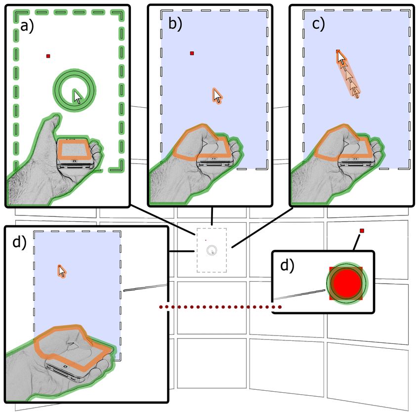
are giving rise to new working scenarios in which users are not sit- Figure 1: LOP-cursor usage to select and move objects on a tiled
ting in front of the screen nor they have a table upon which to pose display: (a) the user hovers the target neighborhoods with an arrow
their mice. A widespread example of this situation are the multi- pointer performing a 3D gesture with a mobile device in the hand;
display screens in operation centers, public spaces and scientific (b) touching the device touchscreen locks the position of a rectan-
facilities. While they offer great visualization possibilities, efficient gular control canvas; (c) fine tune and precise selecting the target
interaction with such displays is still a major challenge. object with the arrow in the control canvas is achieved moving the
thumb on touchscreen; (d) holding the control canvas locked, the
The literature is rich in direct pointing based techniques, many of
user can move the arrow cursor by touchscreen on the mobile de-
which do not necessarily rely on conventional mouse-and-keyboard
vice while moving their hand to point at a second place with a sec-
input (next section comments on a few examples). Although those ondary cursor (ring cursor) to define a destination target to the se-
usually offer fast and intuitive input for pointing tasks while inter- lected object. Green marks indicate actions made using gestures,
acting with large and distant displays, precision of pointing is lim- while orange marks point out actions done on the touchscreen. The
ited due to hand jittering. Moreover, most interaction approaches image background illustrate the LOP-cursor graphic representation
used today in this context do not offer the same resolution for inter- on a tiled display.
action input as the resolution offered by the displays. This problem
is related to input device limitations but also to the cursor metaphor
in use.
On the other hand, small multi-use devices as cell phones and, Different combinations of sensor sets enable a number of position-
more generally, smartphones with sophisticated high-resolution ing and orientation possibilities for interaction with external facil-
small screens are more ubiquitous than specific devices. Those mo- ities by means of personal mobile devices. While literature covers
bile devices are complete devices, with a number of sensors (GPS, quite well the use of camera and touch based mobile device inter-
accelerometers, gyroscope, magnetometer, multi-touch screens, action techniques [2, 8, 4, 5, 9, 17, 13], sensors of movement and
cameras, etc.) and networking capabilities (3G, wi-fi, bluetooth). their possible combinations are less explored [19, 10, 7].
In this paper we introduce the LOP-cursor, a multilevel and two-
∗ e-mail: hgdebarba@inf.ufrgs.br legged cursor for interaction with large high-resolution displays
† e-mail:nedel@inf.ufrgs.br based on a combination of 3D and 2D interaction metaphors. By
‡ e-mail:amaciel@inf.ufrgs.br freely walking in front of the display area, the user changes their
position and distance to the screen, emulating pan and scale of the
visualization in relation to himself.
LOP is a cursor metaphor in which the accurate cursor position-
ing is based on two levels of precision. The two levels are necessary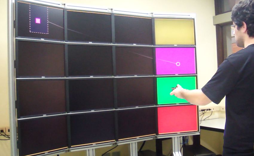
to address the lack of precision observed in many single level direct     with video to mobile devices [4]. Touch Projector uses a polygon
pointing techniques. With LOP-cursor, the user first points the de-       comparing algorithm to identify the screen where the user is aim-
vice towards the target on the screen using the laser pointing 3D         ing, thus allowing the control over multiple and spread displays.
metaphor. If higher precision is needed, the user can fine tune the       Touch Projector also suggested improvements to the video interac-
cursor position by sliding a finger on the device’s touchscreen, at       tion concept, based on mobile device specific constraints and needs.
this point using a 2D interaction technique. Figure 1(a to c) illus-      Later, Boring et al. extended Touch Projector to interact with media
trates a walkthrough on positioning the cursor as a combination of        facades [5]. LightSense [16] uses a mobile phone with a back LED
the two levels.                                                           over a semitransparent table and track its two dimensional position
    The fine tuning by touchscreen freezes a control canvas through       using an external optical tracking system. The LED diffusion over
all the duration of the touch, but does not stop the direct 3D pointing   the table is also used to distinguish across ten levels of distance
feature, which results in two simultaneous cursors under the control      between table and device.
of the user. This design allows two simultaneous pointing locations          None of the presented techniques deal with the precision issue
(the two legs of the cursor) to quickly perform composed tasks as,        at the level we are proposing. Presented pointing techniques are
for instance, selection and move. Figure 1(a, b and d) presents the       all based on camera tracking and/or ray casting with low cost ap-
walkthrough on the simultaneous use of both legs of the cursor.           proaches, thus resulting in less precision of pointing. The mo-
Ninja Cursors [11] is the only other approach that allows simulta-        tion sensors embedded in the newer smartphones allow for a num-
neous control over multiple cursors. However, it only replicates the      ber of gesture-based input modalities. Specific pointing devices
mouse movement across cursors aiming to reduce the index of dif-          (Wiimote, gyro mice...) make extensive use of these sensors, but
ficulty of selection tasks, while we aim at allowing simultaneous         generic smartphones have not been widely explored for pointing
pointing at two specific places at the same time.                         tasks. WYSIWYF [19] uses accelerometer readings and prongs
    The contributions of this paper are twofold:                          contact with a smart board to position and orient a volume cutting
                                                                          plane. Touching the smart board with the mobile device creates a
    • An approach for high resolution interaction with large high         virtual plane that starts from the contact points between the mobile
      resolution displays based on two levels of precision using 3D       device and the smart board which have the same orientation of the
      and 2D interaction metaphors                                        device. Katzakis and Hori [10] used mobile device accelerometers
                                                                          and digital compass to orient 3D objects applying a direct mapping
    • A two-legged cursor concept defining two simultaneous posi-         of orientation across them. On a comparative test, the mobile device
      tions using only one hand                                           approach performed better than mouse and touchpen input. Other
                                                                          works used movement sensors for tasks like distinguishing devices
   The remaining of the paper is organized as follows. Section 2          on a multi-touch display wall using tilt correlation [7].
summarizes related works on the use of mobile devices to interact
with large displays as well as input techniques that consider lev-
els of precision. Section 3 presents the decisions and details of the     2.2   Levels of precision input
LOP-cursor design. Section 4 describes the current state of hard-
ware technology and software implementation. In Section 5 we              Switching between absolute and relative modes of input, in some
present the evaluation of the LOP-cursor comparing it against other       sense, allows the use of more than one level of precision for inter-
selection techniques. Finally, in Section 6 we present and discuss        action. Absolute pointing is used for quick traveling long distances,
the results achieved and in Section 7 we highlight our findings and       while relative movements of the cursor are used for fine tuning, thus
suggest future developments.                                              also providing fast and high precision pointing.
                                                                             Vogel and Balakrishnan [20] explored natural input using the
2     R ELATED W ORK                                                      naked hand. The proposed technique allows switching across ab-
2.1    Mobile device control of large displays                            solute and relative input performing two different hand poses. The
                                                                          user can point to a region at the large screen performing an absolute
Ballagas assumed that the smartphone is the first really pervasive
                                                                          hand pose, and then, change the hand pose to switch to the relative
computational device [1], being an essential part of contempora-
                                                                          mode. Similar in concept, Forlines et al. also implemented an anal-
neous life and an always on pocket device. Therefore, its use as
                                                                          ogous for pen interaction with large and high resolution touch sur-
an input/output device is quite obvious. Most relevant works using
                                                                          faces [6]. Users could switch from absolute to relative input mode
mobile devices to control external large displays are based on op-
                                                                          to achieve targets out of their arms reach area. Both techniques
tical analysis, usually relying on optical flow [2, 8], pattern recog-
                                                                          rely on high cost aparatus and a prepared interaction environment
nition [2, 4, 5, 8, 9, 17], and external optical tracking of the device
                                                                          (VICON tracking system).
[16]. Other works also use mobile devices sensors on less specific
tasks [19, 10, 7].                                                           Nancel et al. [14] also proposed a technique using the VICON
   Ballagas et al. are precursors on mobile phone interaction with        system. They combine a VICON-based ray casting mode with a
large displays, introducing the Sweep and Point and Shoot tech-           precise relative pointing sliding the finger on an Apple iPod Touch
niques [2]. Sweep uses the optical flow to move a cursor on the           device touchscreen. The touch surface is divided in two areas: an
screen, with a central button as a clutching activator. Point and         upper zone for tracking, and a lower zone for clicking. Touching the
Shoot uses a quick blink of bi-dimensional tags on the controlling        upper zone switches to precise mode. Authors claim it is possible
screen synchronized with the camera capture order, allowing recon-        to select objects with 4 millimeters standing 2 meters away from
struction of camera pointing center. Jiang et al. [9] use the two last    the display, which is comparable to some results we show in this
on screen cursor positions to define a coordinate system, allowing        paper using only smartphone built-in sensors.
the cell phone to calculate the new position the cursor should as-           The ARC-Pad [13] implements an absolute plus relative cursor
sume.                                                                     controller using a mobile phone touchscreen. The movement of
   Pears and Olivier introduced a technique for registration of mo-       the finger while holding the touch triggers a relative movement,
bile phone and external displays using four square markers [17].          identical to an ordinary touchpad, but a quick tap on the screen
Registering allows direct mapping of every pixel at the large display     triggers a jump of the cursor to the location defined by an absolute
on the mobile phone screen, and thus, direct control is provided.         mapping relation with the external display. We implemented this
Boring et al. developed the Touch Projector, extending interaction        approach and further compared with LOP-cursor at the Section 5.1.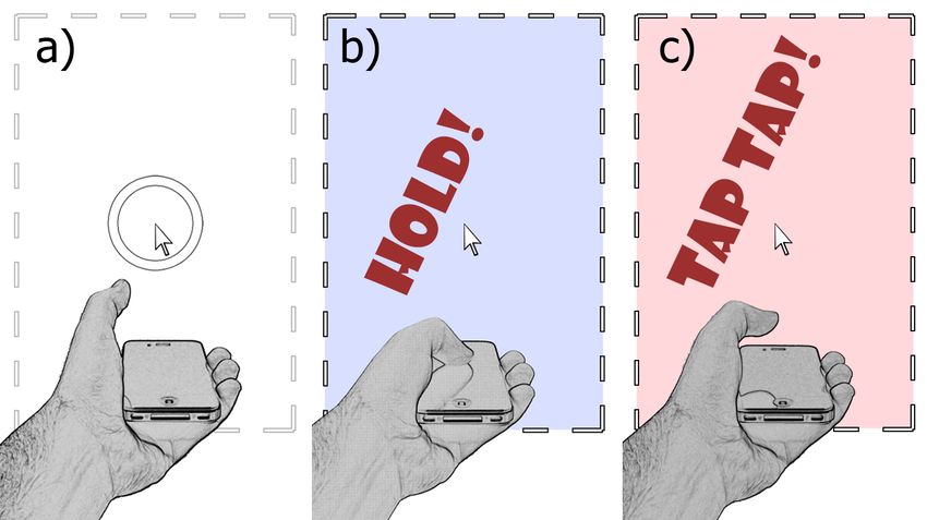
3     D ESIGN                                                                While the leg-1 of the cursor is finely controlled inside the very
3.1     The conception of the LOP-cursor                                  stable control canvas, wrist movements can still displace and rotate
                                                                          the device, giving rise to the leg-2 of the cursor. Leg-2 is then a cur-
LOP-cursor was conceived for high-precision pointing on high-             sor pointer controlled by free-pointing that can be used as a lower
resolution displays. The technique is based on two levels of preci-       precision secondary and simultaneous cursor. Interaction scenarios
sion. In the first level, the user points the device towards the target   for leg-2 are described later in this paper. Touch take-off results in
on the screen, which results in moving a rectangular control canvas       the release of the control canvas. On releasing, the control canvas
containing the cursor arrow to that location (see Figure 1a). If the      silhouette assumes the current position of leg-2, and the two-legged
user succeed on selecting the desired target with the arrow, the task     cursor reunifies, returning to the free-pointing only state.
is achieved. Otherwise, a fine tuning can be done by sliding a fin-
ger on the device touchscreen, moving the cursor arrow inside the         3.2.3    Pin-control-canvas + free-pointing
control canvas (see Figures 1b and 1c). Different from most 2 lev-        Starting from a free-pointing state, a double tap on the device touch-
els of input techniques, LOP-cursor uses absolute mapping in both         screen pins down the control canvas (Figure 2c). Pinning position
levels, ray casting for the first level, and a rectangle representing     is defined by the pointing position at the start of the first tap, which
the physical device touchscreen at the large display. During the fine     minimizes the occurrence of pinning on an undesired position due
tuning, the position of the control canvas is locked, but the coarse      to device displacement while tapping.
pointing using the ray casting metaphor remains active (see Fig-             While pinned, the touch take-off does not trigger a state change.
ure 1d). This feature – the simultaneous use of the two legs of the       The state is maintained until the user performs another double tap.
cursor – inspired the use of LOP-cursor to perform composed tasks,        This allows for a number of touchscreen actions to be performed.
as select-and-move, for instance.                                         For example, a single tap can be used for selection. Meanwhile,
                                                                          sliding a finger is used to fine pointing inside the control-canvas
3.2     Cursor States
                                                                          analogously to the hold-control-canvas state above. This state al-
The three-dimensional interaction space of our cursor metaphor            lows more stable use of simultaneous cursors.
combined with its two legs allows for an increased pointing ca-
pability. To ensure user control while keeping flexibility in this        3.3     Graphic representation
context, we defined three states of interaction for the cursor: (1)       Four complementary shapes are used to represent the LOP-cursor
free-pointing state; (2) hold-control-canvas + free-pointing state;       which are combined to maximize usability. They are described here
(3) pin-control-canvas + free-pointing state. The states are detailed     in association with the terms already used above to introduce the
below and depicted in Figure 2.                                           cursor states.

                                                                          3.3.1    Arrow: the leg-1 pointer
                                                                          To benefit from the high precision positioning capability of LOP-
                                                                          cursor, a traditional point selector over an area selector was pre-
                                                                          ferred for our main cursor design. We used the well known arrow
                                                                          shape to represent this cursor, which minimizes ambiguities. We
                                                                          believe that using the arrow to highlight the leg-1, which is the ulti-
                                                                          mate pointer in LOP-cursor, helps users to immediately differenti-
                                                                          ate it from the other shapes we used.
                                                                              The arrow opacity depends on the size of the nearest target to
                                                                          the cursor, the cursor size itself, and the distance between the target
                                                                          and the arrow center. Using adaptive opacity avoids the occlusion
                                                                          of very small targets by the arrow and allows users to keep track of
Figure 2: LOP-cursor states: (a) free-pointing; (b) holding a touch
                                                                          the target whenever it is required. Figure 3 illustrates the arrow and
leads to hold-control-canvas + free-pointing, (c) a double tap activate   its opacity function.
and deactivate pin-control-canvas + free-pointing.
                                                                          3.3.2    Rectangle: the control canvas
                                                                          A rectangle is used as the representation of the mobile device touch-
3.2.1    Free-pointing                                                    screen on the display. It defines a control canvas within which the
                                                                          arrow is. An absolute mapping is used between the device’s rectan-
This is a one-legged cursor mode (Figure 2a). While on free-              gular touchscreen and the control canvas, e.g. a touch at a location
pointing state, cursor positioning is allowed on a direct-pointing        near a corner of the touchscreen results in placing the arrow at the
only manner. In this state, our metaphor is very similar and, in av-      same corner of the control canvas. This absolute approach makes
erage, not worse than a ray casting based technique, allowing large       the rectangle a natural choice for the virtual representation of the
targets to be easily acquired. Small differences in performance can       touchscreen. More important, this approach allows for the control
appear depending on the way position and direction are gathered,          canvas representation to contain an input resolution equivalent to
and difficulties related to small targets remain an issue.                that of the device’s touchscreen sensing resolution (480 x 320 in
                                                                          our implementation). The rectangle has also the same aspect ratio
3.2.2    Hold-control-canvas + free-pointing                              of the touchscreen, making the correspondence explicit to the user.
In this state, the two legs of the cursor are active and can be defined      To allow user control over the leg1 cursor precision, pinch and
(Figure 2b). The cursor enters this state when a touch on the mo-         stretch gestures resize the control canvas proportionally to its cur-
bile device touchscreen is hold. While in hold, the control canvas        rent size. In our implementation, the default input scale is 1:2,
keeps the initial touch pointing position as its anchor, so that the      where each pixel on the touchscreen is represented by a 2x2 area
user can fine tune pointer positioning by sliding the finger on the       of pixels at the large screen. For instance, to achieve higher preci-
touchscreen. Unlike most touchpads, here touch is mapped with an          sion, the user can resize the control canvas to a 10:1 precision, and
absolute relation between the devices touchscreen and the control         thus, a 10x10 area of pixels on the touchscreen would be mapped
canvas.                                                                   to only 1 pixel of the large screen.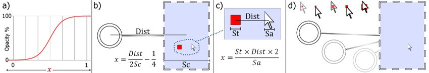
Figure 3: A logistic function maps the arrow and ring opacity according to the x variable value (a); x for the ring depends on distance between
the center of the ring and the center of the rectangle Dist, and the width of the rectangle Sc (b); x for the arrow depends on distance between
center of the target and center of the arrow Dist, and width of arrow Sa and target St (c); arrow and ring opacity sample results for a variety of
target sizes and positions, and rectangle and ring distances (d).

3.3.3    Ring: the leg-2 pointer                                            place and the rectangle (canvas) is placed accordingly to compen-
We chose a relatively large ring shape instead of an arrow for leg-2        sate the distance of the touch from the center. Although this causes
because it is subject to jittering and precision cannot be guaranteed.      a small motion discontinuity for the canvas (it is small because the
   Leg-2 indicates the physical pointing direction of the device. It        users tend to touch at the center of the device touchscreen), it was
always follows the device’s orientation, enabling the user to keep          preferred than a discontinuity of the arrow as the user focus is on
track of where they are pointing to. This is particularly relevant          the arrow.
when the control canvas is in hold or pinned and the two legs are
separate. In this occasions, when the focus of the user is on leg-1,        4     P ROTOTYPE I MPLEMENTATION
involuntary hand movements eventually take the ring to locations            We implemented the LOP-cursor in the context of an experimen-
far from the control canvas and the leg-1 arrow. After release, the         tal interface. Our prototype consists of interaction challenges that
control canvas jumps back to follow the device’s orientation and            cover many of the interaction needs when working with large high
consequently the location of the leg-2 ring pointer. Experiments            resolution displays. The challenges are simple selection, drag and
show that while this jump does not seem to upset the user, it can           classification tasks with low cognitive load. Real world applica-
cause disorientation when the ring pointer is not displayed.                tions, which can also involve 3D environments, are not addressed
   To avoid distraction caused by continuous movement of the ring           here.
near the arrow, we used an adaptive opacity factor. The ring opacity
is proportional to its distance from, and size of, the control canvas.      4.1    Hardware and Software
The nearer the ring is from the control area, more transparent it is.       Input and output hardware in our implementation consist respec-
Figure 3 illustrates the concepts above.                                    tively of a smarphone and a tiled display wall.
                                                                               Our display wall is a 16 LCD monitors tiled-display, disposed
3.3.4    Line: a bridge between leg-1 and leg-2                             on a 4 x 4 matrix. Each monitor has 1,680 x 1,050 pixels and 22
A line is used for connecting the control canvas (rectangle) and the        inches diagonal. The total pixel count is 6,720 x 4,200 = 28,224,000
leg-2 (ring). This aids the user to keep track of the relative position     pixels (≈28 megapixels). The display wall is controlled by four PC
of legs 1 and 2 and to warn where they are currently pointing to.           Core2Quad, with two NVIDIA GTX 285 each. See Figure 4 for an
The line is specially useful when the two legs are separated by a           overview photograph of the prototype in operation.
large distance. For example, while simultaneously working with                 The smartphone used in our main implementation is an Apple
the two cursor legs, the user will need to quickly switch attention         iPhone 4. An iPod Touch (fourth generation) was also used for
between them. The line guides searching direction, while the color          preliminary and comparative testing. As the smartphones used do
intensity guides on the distance between legs.                              not present a general purpose embedded back button, we adapted
                                                                            a Microsoft Wireless Mobile 3500 Mouse, which offered a reliable
3.4     Transitions between states                                          wireless communication.
While in free-pointing state, both the arrow and ring pointers follow
the mobile device pointing direction. The arrow is kept at the center       4.2    Orientation acquisition
of the ring, and a semi-transparent rectangle with dashed borders is        In our prototype, we adapted the strategy proposed by Madgwick
shown to keep the user aware of the size of the control canvas. As          [12] which combines gyroscope, accelerometer and digital compass
the control canvas and the ring cursor are superposed and move              information to gather a more robust orientation. This orientation ac-
together, the line is not visible in this mode.                             quisition method relies on the gyroscope to provide instantaneous
    When switching from free-pointing to hold-control-canvas +              orientation changes (providing 3 axes angular rate of change), and
free-pointing, or from free-pointing to pin-control-canvas + free-          gradual adjustments using two distinct vectors related to absolute
pointing, a transition effect is played to guide user attention across      frames of reference, the accelerometer and the magnetometer (re-
states. The effect renders the rectangle with more opacity, and ring        spectively related to gravity and magnetic north pole). In practice,
transparency is controlled as described in Figure 3, giving a hint of       we correct gyroscope cumulative rotational error in two axis using
switching modes. The inverse effect is played when returning to the         the accelerometer (roll and pitch) and in a third axis using the mag-
free-pointing-only state. To inform the user about the current state,       netometer (yaw).
holding fills the rectangle with a blue transparent tone, and pinning          Magnetometer readings are less precise and more error prone
fills the rectangle with a red transparent tone.                            than accelerometer readings, suffering from magnetic interference
    In preliminary tests, due to absolute pointing within the con-          from near metal structures. Raw readings from the iPhone oscillate
trol canvas, the arrow cursor often jumped when entering in hold-           within the range of 10% in our environment. Although it does not
control-canvas + free-pointing state. This caused a discontinuity           seem too much, it is crucial to understand that, as a ray is casted
that led the users to report some disorientation. To overcome this          using device orientation, any variation is greatly magnified. Be-
issue, in the final design of the LOP-cursor the arrow is kept in           cause of that, two additional steps were implemented to allow long
5 E VALUATION
We conducted two sets of user tests, both using the prototype pre-
sented in Section 4: a comparative evaluation, and a deeper ex-
ploration of the LOP-cursor capabilities.In all tests, target start and
goal positions were constrained to never intercept a monitor bezel
since, as stated by [3], this can be detrimental to some user interac-
tion aspects.
5.1 Comparative evaluation
5.1.1 Design
To validate the LOP-cursor technique, we conducted a compara-
tive evaluation on a selection task. LOP-cursor was compared to
an ARC-pad [13] implementation, and a Ray Casting using only
device orientation (ORayCasting), a technique equivalent to limit-
ing LOP-cursor to the use of the lower precision level of pointing.
Figure 4: Prototype overview. This photograph depicts a user inter- To remove subjective bias on choosing the level of precision, the
acting with the two legs of LOP-cursor. Notice that while leg-1 selects LOP-cursor implementation used for evaluation constrained users
a square on the left, the leg-2 ring indicates the location on the right to always use the two levels of precision for selections. We call
to where the square will be moved. this implementation (CLOP-cursor). CLOP is actually the same as
the original LOP but free-pointing is not effective for selection trig-
gering. Thus, with the CLOP-cursor, users had to always perform
term use of the smartphone as a pointing device. In the first step, steps a through c as described in Figure 1.
to force the magnetometer to only adjust yaw drift error, the tridi- Independent variables are: Technique: ARC-Pad, LOP-Cursor
mensional vector provided is projected into a plane orthogonal to and ORayCasting. Target Size: 0.5cm, 1cm, 2cm, 4cm. Target Dis-
the accelerometer vector. In the second, to ignore high frequency tance: 25cm, 50cm, 100cm. Dependent variables are: Time and Er-
magnetometer reading variations, instead of using a filter – which ror rate. We used a within-subject design. Technique exposure was
would result in poorer interaction due to delay – we are using a re- counter-balanced, while size and distance of target were randomly
dundancy controller based on the gyroscope updates. More specifi- presented. Pointing to a target and triggering a selection counted
cally, in this step we ignore small variations from the magnetometer as a Trial. There were a total of 10 Trials for each independent
readings whenever the gyroscope readings cannot confirm that a ro- variable combination. Each technique evaluation was divided in 5
tation actually occurred around that axis. Blocks, where a Block = Sizes x Distances x 2 Trials, giving a total
of 24 Trials per Block. The first 2 Blocks were used for practicing,
4.3 Position calibration and thus are not considered on further analysis. Participants were
As smartphones and other every-pocket mobile devices are not allowed to take a non-mandatory break between blocks.
equipped with position tracking, we used only orientation to define After the comparative evaluation, another selection test where
pointing and assumed a constant position of the user while testing the complete LOP-cursor is used was taken. In this case, subjects
our prototype. To define this position and reconstruct rotational were not constrained to always use the higher level of precision.
zero position of the device, our system uses a calibration step. No- They could decide when and if they want to use two levels of preci-
tice that this step is not necessary when position tracking is used. sion, or only one. This was intended to evaluate for which sizes of
For magnetometer calibration, the device must be placed face up target users preferred to use only the ray casting level of precision,
pointing orthogonal to the plane defined by the display. A calibra- or both of them, thus allowing us to infer if participants subjective
tion command registers an orientation offset. Next, the calculation preference match to the previously applied comparative evaluation
of approximate user position (P3 ) is achieved registering two orien- best times per size. Six target sizes were used: 0.5cm, 1cm, 2cm,
tations of the device. The user is asked to aim the device at a blue 4cm, 8cm, 16cm. Each test had 5 Blocks of 18 Trials, 3 trials per
point P1 at one corner of the screen, and then at a red point P2 at size condition. First 2 Blocks were used as training, thus being dis-
the opposite corner. This calibration method assumes that the real carded for analysis.
distance between blue and red dots is known, and that the display Active targets were drawn in red on a black background. To
is perpendicular to the world Z axis. avoid bias from visual search, the following target was shown in
The two registered orientations are used to retrieve two nor- a dark grey tone. There was an additional starting target at each
malized vectors ~v1 and ~v2 . A third vector ~v3 is calculated as Block. During all evaluation, the user was positioned centered to the
~v3 = P2 − P1 . The angles α1 between ~v1 and ~v2 , α2 between −~v1 tiled-display, at a constant distance of 150cm. Users who completed
and v̂3 , and α3 between −~v2 and −v̂3 are computed by dot product. all the evaluation were then asked for their preferred interaction
The length of the segments given by ~v1 and ~v2 , respectively, are technique (CLOP-cursor, LOP-cursor, ARC-pad or ORayCasting),
calculated as and allowed to leave general comments and observations about the
evaluation. Users were asked to favor precision over speed.
|~
v3 |sin(α2 ) |~v3 |sin(α3 )
l1 = , l2 = . (1) 5.1.2 Implementation details
sin(α1 ) sin(α1 )
Comparative tests were taken using an iPod Touch 4th generation.
Then, we estimated device positions P30 = P1 + l1 (~v1 )−1 and Orientation without the magnetometer recalibration may drift on
P300= P2 + l2 (~v2 )−1 . A mid point between P30 and P300 is used as Yaw over time (see Section 4.2), but the ray casting was too im-
the final P3 . precise when using yaw corrections because of the high variability
Limitations of this calibration approach is that significant of the magnetometer readings from the iPod. As this would put
changes in the position of the user will result in the need for a the ORayCasting technique in disadvantage relating the other tech-
new calibration, or at least some cursor offset control. Also, the niques tested we disabled yaw corrections. To limit the effect of
rotational zero will depend on which of the joints (shoulder, elbow, yaw drifting we preferred to arrange short blocks of trials (24 tri-
wrist) the user performs the rotations. als) and frequently correct any drift between blocks.The ARC-pad paper [13] does not make clear how a selection is 6 R ESULTS AND D ISCUSSION
triggered, and seems to suggest its use over a desk. Our test design, 6.1 Comparative evaluation
instead, proposes the users to stand in front of the screen, and thus
they had to hold the device with both hands to maintain consistent Eleven participants took place on this evaluation, (mean age 22, 2
aspect ratio orientation across the tiled display and the mobile de- women and 2 left handed) all of them Computer Science students
vice. Selection was implemented using a Tap gesture from the sec- (10 undergraduate, 1 master student). Most of them had previous
ondary hand while holding arrow position with the primary hand. experience with pointing devices (mostly Wii gaming), all of them
See Section 2.2 for a brief description of the ARC-pad technique. had at least some experience with a mobile device touchscreen, only
Cursor position was filtered using a dynamic low-pass filter, in- two had significant experience with very large displays.
terpolating between cutoffs of 0.2Hz and 5Hz, with 60Hz sample From the comparative test we had 2,376 total valid Trials. A
rate. Cutoff is defined according to cursor speed: when < 1cm/sec, trial was considered a false positive (accidental selection triggering)
lower cutoff is used (0.2Hz); when > 50cm/sec, higher cutoff is when selection occurred at any of the following cases: 20cm or
used (5Hz). For any speed between these, a linearly interpolated farther from the target; less then 200ms after the previous trial was
cutoff value is used. completed. CLOP-cursor, ARC-pad and ORayCastig presented 2,
6 and 9 false positives respectively. These Trials were overlooked
on further analysis.
5.2 In depth LOP-cursor evaluation All subjects completed the comparative evaluation, but three
5.2.1 Design of them could not complete the last evaluation (using the non-
constrained LOP-cursor). This was due to the long time taken by
We conducted this deeper evaluation to assess the limits of our tech-
the comparative evaluation (from 30 to 40 minutes to complete), re-
nique in terms of precision, and to initiate the study on simultaneous
sulting on schedule and fatigue issues for some subjects. This test
cursors. Experiments consisted on completing three different tasks
had a total of 432 trials, 2 of which false positives.
using LOP-cursor:
General mean time for a selection with CLOP-cursor, ORayCast-
Task 1. Pointing and selecting targets. A trial is complete when ing and ARC-pad were respectively: 2.55, 2.46 and 3.05 seconds.
the target is hit. One-way ANOVA showed that ARC-pad was significantly slower
Task 2. Pointing, selecting, dragging and docking targets. Users than CLOP-cursor (F(1.1574)=76.58, pFigure 5: Mean time spent to select targets of different sizes using CLOP-cursor, ORayCasting, ARC-pad and LOP-cursor, and their respective
standard deviations.
Figure 8: Users preferred level of precision for a variety of target
sizes when using LOP-cursor, and their respective trials mean time.
Figure 6: Error rate to select targets of different sizes using CLOP-
cursor, ORayCasting, ARC-pad and LOP-cursor.
cursor and the Ninja Cursors as their evaluation is based on a 2
screens desktop environment, while ours pursuit interaction with
much larger and higher resolution displays, away from the desktop
and with potential to interaction in 3D environments. Nevertheless
we could notice that while the performance of the LOP-cursor is
independent of screen target density, the performance of the Ninja
Cursors is significantly affected by both the number of cursors and
the target density.
Figure 7: Error rate to select targets of different sizes using LOP-
cursor, and individual error rate for each level of precision.
the 3 tasks. Notice that although the larger targets allow for faster
task completion, the time difference is always inside the standard
deviation, regardless of the huge difference (more than one degree
of magnitude) in objects size.
There were 5 false positives (incidental docking) on Task 2,
which were discarded for further results. Mean docking distance Figure 9: Mean time for completion of each trial of each task.
error is 0.17 cm, being 0.158 cm, 0.162 cm, 0.176 cm and 0.188
cm for target sizes with 0.3 cm, 0.8 cm, 1 cm, and 2 cm, respec-
tively. Docking distance error difference per size showed not to be 7 C ONCLUSIONS AND F UTURE W ORK
significant (F(3.255) =1.38, ping two locations on the screen to complete the operation (copy 28th international conference on Human factors in computing sys-
files, arrange photographs, etc.). tems, CHI ’10, pages 2287–2296, New York, NY, USA, 2010. ACM.
Concerning the devices, our pointing method requires both the [5] S. Boring, S. Gehring, A. Wiethoff, A. M. Blöckner, J. Schöning, and
orientation and position of the mobile device. Orientation is re- A. Butz. Multi-user interaction on media facades through live video
trieved using device built-in movement sensors. In our prototype, on mobile devices. In Proceedings of the 2011 annual conference
position is assumed or given by a simple calibration step. A track- on Human factors in computing systems, CHI ’11, pages 2721–2724,
ing system for position would perfectly fit and enhance our concept, New York, NY, USA, 2011. ACM.
[6] C. Forlines, D. Vogel, and R. Balakrishnan. Hybridpointing: fluid
but as tracking requires more complex equipment, we preferred to
switching between absolute and relative pointing with a direct input
keep the solution available for everyone who owns a smartphone.
device. In Proceedings of the 19th annual ACM symposium on User
We continue working on LOP-cursor, investigating the use of interface software and technology, UIST ’06, pages 211–220, New
simultaneous cursors on real life tasks and alternative screen con- York, NY, USA, 2006. ACM.
figurations. Further investigations will be held in order to determine [7] W. Hutama, P. Song, C.-W. Fu, and W. B. Goh. Distinguishing mul-
to which level users control two cursors simultaneously or one at a tiple smart-phone interactions on a multi-touch wall display using tilt
time. In addition, we want to access two-legged cursor cognitive correlation. In Proceedings of the 2011 annual conference on Human
load and determine which two-location tasks may benefit from this factors in computing systems, CHI ’11, pages 3315–3318, New York,
metaphor. We plan to apply our concept on distributed computing NY, USA, 2011. ACM.
scenarios, with many computers and screens that do not necessarily [8] S. Jeon, J. Hwang, G. J. Kim, and M. Billinghurst. Interaction tech-
respect a position pattern, but rather are distributed across the room. niques in large display environments using hand-held devices. In Pro-
Such scenarios can benefit from LOP-cursor for tasks such as file ceedings of the ACM symposium on Virtual reality software and tech-
transfer across computers, where the user can pin control canvas nology, VRST ’06, pages 100–103, New York, NY, USA, 2006. ACM.
on a high resolution display (computer 1), while controlling the file [9] H. Jiang, E. Ofek, N. Moraveji, and Y. Shi. Direct pointer: direct
destination pointing to another display (computer 2, 3, 4 ...) with manipulation for large-display interaction using handheld cameras. In
leg-2 cursor. Future works also include the study of leg-2 serving Proceedings of the SIGCHI conference on Human Factors in comput-
as a controller for another dimension, such that, its distance from ing systems, CHI ’06, pages 1107–1110, New York, NY, USA, 2006.
ACM.
(or circular movement around) the leg-1 can control selected object
[10] N. Katzakis and M. Hori. Mobile phones as 3-dof controllers: A com-
attributes(scale/depth/orientation).
parative study. In Dependable, Autonomic and Secure Computing,
Although the LOP is based on 3D interaction techniques, the 2009. DASC ’09. Eighth IEEE International Conference on, pages 345
evaluation in this paper focuses on a controlled 2D task. Neverthe- –349, dec. 2009.
less, we see a great potential for using the LOP in 3D environments. [11] M. Kobayashi and T. Igarashi. Ninja cursors: using multiple cursors to
One possibility we are investigating is to control the canvas orienta- assist target acquisition on large screens. In Proceeding of the twenty-
tion in R3 using the device’s orientation while pinned. We believe sixth annual SIGCHI conference on Human factors in computing sys-
in this approach based on works in the literature showing that users tems, CHI ’08, pages 949–958, New York, NY, USA, 2008. ACM.
quickly map 2D displacements from a given plane to any arbitrary [12] S. O. H. Madgwick, A. J. L. Harrison, and R. Vaidyanathan. Estima-
plane, as for instance, the mouse on a table to the arrow cursor on tion of imu and marg orientation using a gradient descent algorithm.
a screen. Non-desktop 3D environments, as a CAVE, could benefit In Rehabilitation Robotics (ICORR), 2011 IEEE International Con-
from the bases of LOP-cursor with some incremental development ference on, pages 1 –7, 29 2011-july 1 2011.
to add these arbitrary planes. [13] D. C. McCallum and P. Irani. Arc-pad: absolute+relative cursor posi-
We also plan to investigate how the user distance from the screen tioning for large displays with a mobile touchscreen. In Proceedings
and the screen size affects the optimal scale for the control canvas. of the 22nd annual ACM symposium on User interface software and
As stated by Peck et at. [18], users tend to interact in different scales technology, UIST ’09, pages 153–156, New York, NY, USA, 2009.
ACM.
according to their distance from screen. Naturally, when users are
[14] M. Nancel, E. Pietriga, and M. Beaudouin-Lafon. Precision Pointing
near the display, they can see and point with more precision, and
for Ultra-High-Resolution Wall Displays. Research Report RR-7624,
thus, a smaller control canvas allowing more precision would also INRIA, May 2011.
make sense (Section3.3.2). [15] T. Ni, G. S. Schmidt, O. G. Staadt, M. A. Livingston, R. Ball, and
R. May. A survey of large high-resolution display technologies, tech-
ACKNOWLEDGEMENTS niques, and applications. In Proceedings of the IEEE conference on
Virtual Reality, VR ’06, pages 223–236, Washington, DC, USA, 2006.
This work was supported by CNPq-Brazil under the
IEEE Computer Society.
projects 309092/2008-6, 483947/2010-5, 483814/2010-5 and
[16] A. Olwal. Lightsense: enabling spatially aware handheld interaction
302679/2009-0. Thanks are due to all the volunteers who kindly devices. In Proceedings of the 5th IEEE and ACM International Sym-
tested the system. posium on Mixed and Augmented Reality, ISMAR ’06, pages 119–
122, Washington, DC, USA, 2006. IEEE Computer Society.
R EFERENCES [17] N. Pears, D. G. Jackson, and P. Olivier. Smart phone interaction with
[1] R. Ballagas, J. Borchers, M. Rohs, and J. G. Sheridan. The smart registered displays. IEEE Pervasive Computing, 8:14–21, April 2009.
phone: A ubiquitous input device. IEEE Pervasive Computing, 5:70–, [18] S. M. Peck, C. North, and D. Bowman. A multiscale interaction tech-
January 2006. nique for large, high-resolution displays. In Proceedings of the 2009
[2] R. Ballagas, M. Rohs, and J. G. Sheridan. Sweep and point and shoot: IEEE Symposium on 3D User Interfaces, 3DUI ’09, pages 31–38,
phonecam-based interactions for large public displays. In CHI ’05 Washington, DC, USA, 2009. IEEE Computer Society.
extended abstracts on Human factors in computing systems, CHI EA [19] P. Song, W. B. Goh, C.-W. Fu, Q. Meng, and P.-A. Heng. Wysiwyf:
’05, pages 1200–1203, New York, NY, USA, 2005. ACM. exploring and annotating volume data with a tangible handheld device.
[3] X. Bi, S.-H. Bae, and R. Balakrishnan. Effects of interior bezels of In Proceedings of the 2011 annual conference on Human factors in
tiled-monitor large displays on visual search, tunnel steering, and tar- computing systems, CHI ’11, pages 1333–1342, New York, NY, USA,
get selection. In Proceedings of the 28th international conference on 2011. ACM.
Human factors in computing systems, CHI ’10, pages 65–74, New [20] D. Vogel and R. Balakrishnan. Distant freehand pointing and clicking
York, NY, USA, 2010. ACM. on very large, high resolution displays. In Proceedings of the 18th
[4] S. Boring, D. Baur, A. Butz, S. Gustafson, and P. Baudisch. Touch annual ACM symposium on User interface software and technology,
projector: mobile interaction through video. In Proceedings of the UIST ’05, pages 33–42, New York, NY, USA, 2005. ACM.You can also read