NQ-E7010 Input/Output Controller Configuration Manual - 2019 Bogen Communications, Inc. All rights reserved. 740-00017G 190215
←
→
Page content transcription
If your browser does not render page correctly, please read the page content below
NQ-E7010 Input/Output Controller
           Configuration Manual

                   2019 Bogen Communications, Inc.
                                All rights reserved.
                                       740-00017G
                                             190215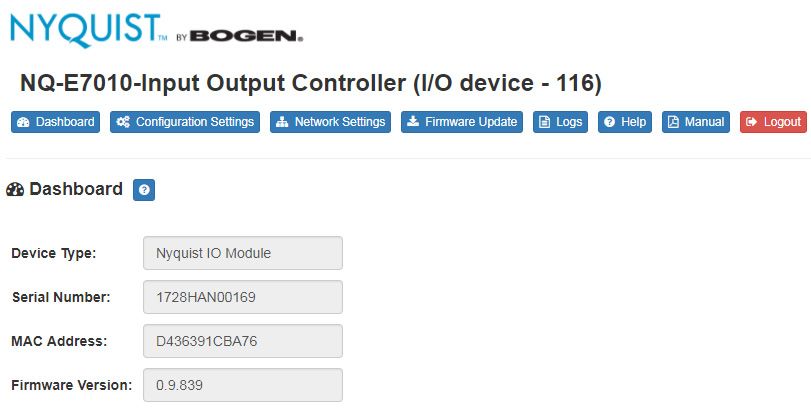
Contents
Configuring the Nyquist Input/Output (I/O) Controller .......................................... 1
                 1 Using the Dashboard...............................................................................3
                 2 Updating Firmware ...................................................................................4
                 3 Setting Network Tab Parameters ........................................................6
                 4 Setting Configuration Tab Parameters .............................................9
                 5 Accessing Log Files................................................................................ 11

                                                                                                                            i
ii
Configuring the Input/
Configuring the Nyquist
OutputNyquist Input/
(I/O) Controller
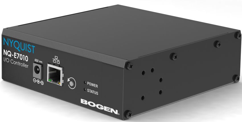
The NQ-E7010 I/O Controller allows Nyquist to recognize third-party
switch contact closures and to provide external circuits. Configuration
rules can be set for each input and output port on this appliance, so,
for example, you can set a rule that if a contact is opened than an
alarm sounds.
Contact closures can be set for specific dates and times using the
Configure Schedule button on the I/O Controller’s Edit Station page.
For example, suppose you want to schedule an output that unlocks a
door at 7:30 each weekday morning. You can set up an output con-
tact closure schedule for 7:30 am Monday through Friday. When the
Activity Time occurs, the contact is closed, which in turn triggers a 3rd
party contact switch that closes the door.
You can let the Nyquist server automatically discover and configure
the I/O Controller, or you can manually configure it through the I/O
Controller’s web-based user interface (web UI).
A short press of the appliance’s Reset button reboots the device. If
you press the Reset button for 10 seconds, the appliance returns to
the factory default configuration settings. Returning to the default
configuration settings does not change the appliance’s firmware.
The following sections describe the process for manual configuration.
For information about using Nyquist’s automatic configuration pro-
cess, refer to the Nyquist System Administrator Manual.
1To access the appliance’s UI:
Note: Do not Step 1 Access the appliance’s web UI by doing one of the fol-
use third-party lowing:
Chrome browser a On your web browser, enter the IP address for the
extensions with appliance as the URL.
the Nyquist user b From the Nyquist web UI navigation bar, select Sta-
interface. tions, select Stations Status, navigate to the device
that you want to configure, and then select the Link
icon.
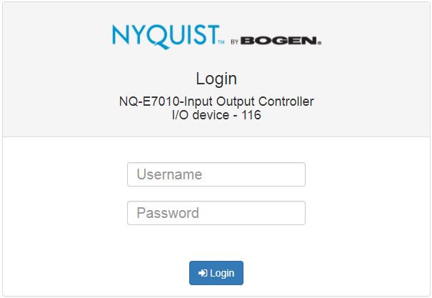
Figure 1, Nyquist Appliance Login
Step 2 At the Nyquist Appliance - Login page, enter username
and password, and then select Login.
The default username is admin; the default password is
bogen.
2The dashboard for the selected appliance appears.
Figure 2, I/O Controller Dashboard
1 Using the Dashboard
The dashboard displays the following read-only fields:
Table 1, Appliance Dashboard Read-Only Fields
Device Type Identifies the physical device used by the
station.
Serial Number Identifies the serial number for the device.
MAC Address Specifies the Media Access Control (MAC)
address, which is a unique identifier
assigned to network interfaces for
communications on the physical network
segment.
Firmware Version Provides the firmware version installed on
the station.
3The dashboard also contains the following buttons:
Table 2, Appliance Dashboard Buttons
Dashboard Refreshes the dashboard.
Configuration Set- Accesses the Configuration Settings page
tings where you can either manually set various
options, such as the SIP Username, or
select to receive configuration settings
from the server.
Network Settings Accesses the Network Settings page where
you can view and set network settings,
such as the static IP address.
Firmware Update Accesses the Firmware Update page where
you can view the current Nyquist version,
check for updates, restore factory settings,
and reboot the appliance.
Logs Accesses log files, which record either
events or messages that occur when soft-
ware runs and are used when trouble-
shooting the appliance.
Help Accesses the appliance’s online help.
Manual Displays the Nyquist I/O Controller Config-
uration Manual.
Logout Logs out of the appliance’s dashboard.
2 Updating Firmware
When you select Firmware Update from the appliance’s web UI, the
Firmware Update page appears. From this page you can determine
which Nyquist version the appliance is using and if an update is
4required. You can also use this page to restore factory settings and to
reboot the appliance.
Note: A Nyquist appliance connected to the Nyquist network receives a config-
uration file from the Nyquist server that includes the latest firmware available
from the server. If the firmware is later than the one installed on the appliance, an
automatic firmware update occurs unless the Firmware parameter for the sta-
tion is left blank. Refer to the Nyquist System Administrator Manual for more
information.
Figure 3, Firmware Update Page
To use the Firmware Update page:
Step 1 On the appliance web UI’s main page, select Firmware
Update to ensure you have the latest firmware version.
Step 2 Select Upload Firmware to upload firmware from the
server to the appliance.
If you select this option, a popup screen appears that
allows you to select the file that you want to upload.
You can navigate to the file’s location. After you select
the file, select Upload. If Nyquist discovers a new firm-
ware version, the Firmware Update page displays an
5Update Firmware button. Select this button if you
want to update the appliance’s firmware to the new
version.
Step 3 If you want to return your appliance to its original state
(undoing firmware updates), select Restore Factory
Settings.
Step 4 Select Reboot Appliance to restart your appliance.
3 Setting Network Tab Parameters
Network settings can be configured dynamically by the Nyquist
server or manually by using the appliance’s web UI.
To manually configure network settings:
Step 1 On the appliance web UI’s main page, select Network
Settings.
Step 2 Select your desired network settings.
Step 3 Select Save.
6Figure 4, Network Settings
Network settings are described in the following table:
Table 3, Network Settings
Static IP Identifies the fixed IP address assigned
to the appliance by a system administra-
tor.
Netmask Identifies the subnetwork subdivision of
an IP network.
7Table 3, Network Settings (Continued)
Gateway Identifies the address, or route, for the
default gateway.
VLAN ID Identifies the Virtual Local Area Network
(VLAN) for this appliance. Values range
from 0 to 4094.
VLAN Priority Identifies the priority of the network traf-
fic on the VLAN. Priority can range from
0 through 7.
NTP Server Identifies the IP address or the domain
name of the Network Time Protocol
(NTP) Server. This field is read only.
TFTP Server Identifies the IP address of the Trivial File
Transfer Protocol (TFTP) server. TFTP is
used by Nyquist VoIP phone and appli-
ance provisioning. A TFTP server runs on
the Nyquist server on port 69 (the stan-
dard TFTP port #).
Device provisioning files are stored on
the Nyquist server in directory: /srv/
tftp. This is the only directory
exposed by the TFTP server.
DHCP Server Over- Indicates if you want to override the
ride TFTP server information provided by the
Dynamic Host Configuration Protocol
(DHCP) via option_66.
DHCP supplies IP addresses to the
Nyquist server and associated devices. It
also supplies the TFTP server IP address
or name via option_66.
DHCP Enabled Indicates if the device is enabled to use
DHCP.
Reboot Appliance Allows you to save the network options
and reboot the appliance.
84 Setting Configuration Tab Parameters
The easiest way to configure Nyquist appliances is to obtain configu-
ration settings from the Nyquist server by selecting Get Configura-
tion From Server. However, you can manually configure an
appliance through the appliance’s Web UI.
Note: Manual configuration will be overwritten by the server once the appli-
ance is connected and discovered by the server.
To manually configure your Nyquist appliance:
Step 1 On the appliance Web UI’s main page, select Configu-
ration Settings.
Step 2 Select your desired settings.
Step 3 Select Save.
9Figure 5, Appliance Configuration Settings
The following table describes the Configuration tab settings:
Table 4, Configuration Settings
Web Username Provide a web username for this appli-
ance.
Web Password Provide a web password for logging into
the appliance.
Web Confirm Pass- Re-enter the password used to log into
word the appliance.
10Table 4, Configuration Settings (Continued)
SIP Username Provide the username used for Session
Initiation Protocol (SIP) device registra-
tion.
SIP Password Provide the password used for SIP device
registration.
SIP Confirm Pass- Re-enter the password used for SIP device
word registration.
Server Identifies the IP address of the Nyquist
server.
Local Port Identifies the local port.
5 Accessing Log Files
A log file records either events or messages that occur when software
runs and is used when troubleshooting the appliance. From the
appliance’s web-based UI, log files can be viewed directly or exported
via download to your PC, Mac, or Android device and then copied to
removable media or attached to an email to technical support.
To view a log file:
Step 1 On the appliance Web UI’s main page, select Logs.
Step 2 From the drop-down menu, select the log that you
want to view.
Multiple versions of the same log and zipped copies of
the log may be available.
Step 3 To export the file, select Export.
A link to a .txt file appears in the screen’s lower left.
11Figure 6, Logs
Available logs are described in the following table:
Table 5, Logs
Log Description
alternatives.log Contains information by the update-alternatives, which
maintain symbolic links determining default com-
mands.
auth.log Contains system authorization information, including
user logins and authentication methods that were
used.
bootstrap.log Contains information actions, errors, and warnings that
occur during booting of the appliance.
btmp Contains information about failed login attempts.
daemon.log Contains information logged by the various back-
ground daemons that run on the system.
debug Contains errors and debug information.
12Table 5, Logs (Continued)
Log Description
dmesg Contains kernel ring buffer information. When the sys-
tem boots up, the screen displays information about
the hardware devices that the kernel detects during the
boot process. These messages are available in the ker-
nel ring buffer, and whenever a new message comes,
the old message gets overwritten.
dpkg.log Contains information that is logged when a package is
installed or removed using dpkg command.
faillog Contains user failed login attempts.
kern.log Contains information logged by the kernel and recent
login information for all users.
lastlog Contains information on the last login of each user.
messages Contains messages generated by Nyquist.
php5-fpm.log Contains errors generated by the PHP script.
syslog Contains list of errors that occur when the server is run-
ning and server start and stop records
user.log Contains information about all user level logs.
wtmp Contains historical record of users logins at which ter-
minals, logouts, system events, and current status of
the system, and system boot time.
wvdialconf.log Contains basic information about the modem port,
speed, init string, and Internet Service Provider (ISP).
1314
You can also read