OG-15 and OG-20 Oxygen Generators - Installation, Operation and Maintenance Manual - OGSI
←
→
Page content transcription
If your browser does not render page correctly, please read the page content below
OG-15 and OG-20
                                            Oxygen Generators
                                     Installation, Operation and
                                           Maintenance Manual

                          Oxygen Generating Systems Intl. (OGSI)
                                Division of Audubon Machinery Corporation
                     814 Wurlitzer Drive, North Tonawanda, New York 14120USA
                  Tel: (716) 564-5165 Toll Free: (800) 414-6474 Fax: (716) 564-5173
                                     E-mail: ogsimail@ogsi.com
                                       Website: www.ogsi.com

Part # 9000000-005                                                                    US $25.00

     Effective 07/2014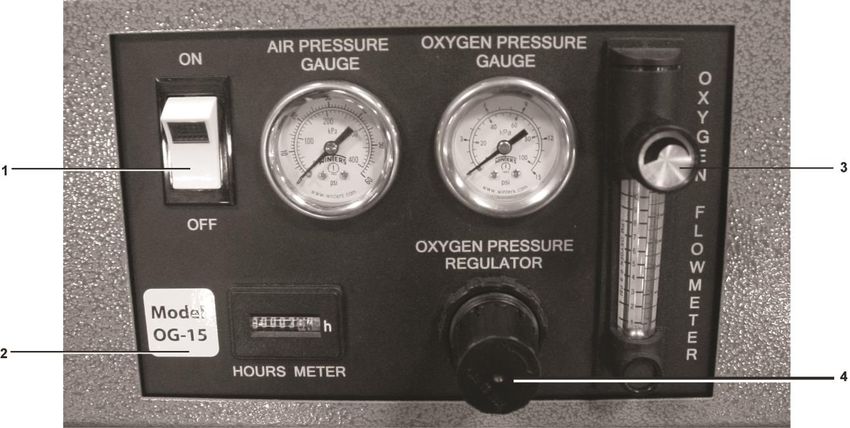
Page left intentionally blank
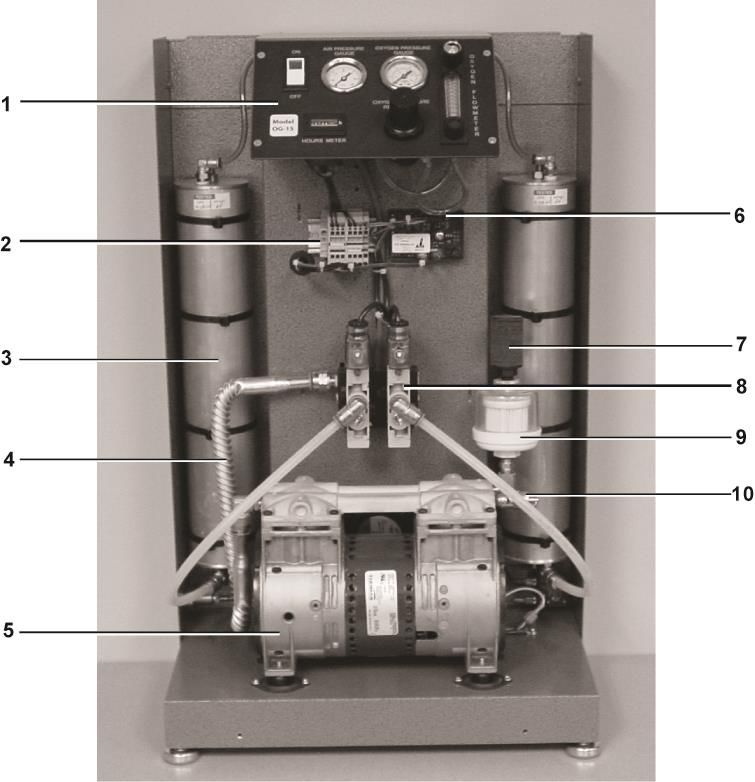
Table of Contents
Topic Page Number
Using this Manual 1
Initial Inspection 2
Warranty Information and Liabilities 3
Safety Guidelines 5-6
Unpacking 5
Operating 6
Product Information 7-32
Features and Applications 7
PSA Technology 9
Components 10
Process Flow Description 26
Specifications 27
Performance Curve 31
Safety Precautions 33
Pre – Installation 34
Required Operating Conditions 35
Set-up and Installation 36
Operating Instructions 37
Troubleshooting Guide 38
Preventive Maintenance 39
Technical Service Assistance 40
Appendix I-X
Certificate of Compliance I
Spare Parts List II
Oxygen Cleaning Procedure IV
Air Changes by Room Size VIII
Units of Measurements IX
Maintenance Log X
Effective 07/2014 Rev C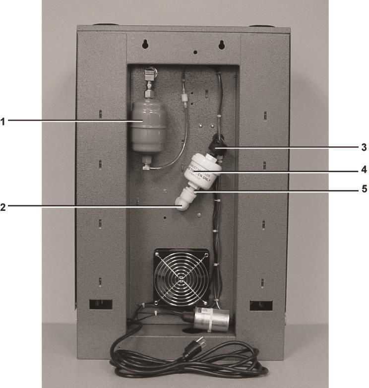
©2014, OGSI. All rights reserved. OGSI is a registered trademark.
This publication may not be reproduced in part or whole without written permission of OGSI.
Using this Manual
This manual is intended as a guide for operators of OGSI Oxygen Generators and
Oxygen Generating Systems. It includes information on our warranty policy, features,
functions, applications, proper set-up and installation, operation and preventive
maintenance of our products.

The following symbols are used throughout the manual:

              Information
              (Do not use product before                       Electrical Hazard
              reading the manual)

              Sound                                            Fire Hazard

              No Smoking                                       Warning

              No Open Flames                                   Power ON/OFF

              Flow Meter                                       Timer

              No Oil                                           Not Connected to Outlet

Effective 07/2014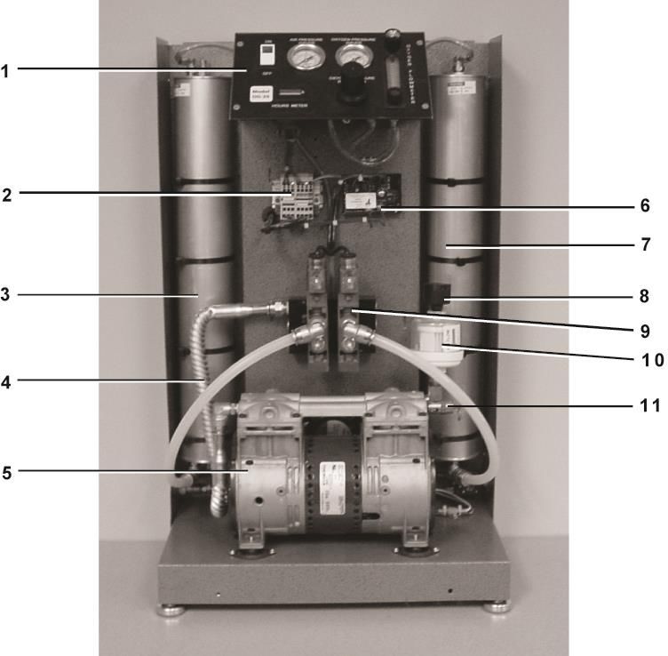
Initial Inspection
        The box should be opened and inspected immediately upon delivery. Unpack the
unit at once and perform a visual inspection to determine if it is dented, bent or scratched.
Also check to make sure the power cord is attached and that the control panel has not
been damaged in any way during shipment.
        If for any reason the unit should need to be returned in the future, the original box
is the best way to ship it back to the manufacturer. Claims of damage due to freight
handling can only be filed by you, the consignee, as OGSI shipping terms are Free On
Board (FOB), North Tonawanda, NY USA. This means that once the equipment leaves
our dock you are the owner of it. OGSI has no legal claim to make against any shipping
company for damage.
        At OGSI, we are committed to using shipping companies with good reputations for
taking care in the overall handling of freight and providing service in the event of damage.
In our experience, we have found United Parcel Service (UPS) to be a poor carrier choice
for equipment of this size and weight. Although they will accept and deliver it, we have
often encountered problems with the way they handle the systems, and recommend other
freight carriers be used. (E.g. Federal Express (FedEx) – Insured shipment)

Effective 07/2014                                                                    2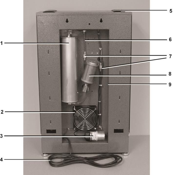
Warranty
        Oxygen Generating Systems Intl., being a division of Audubon Machinery
Corporation (hereinafter OGSI), provides a warranty on its products (the “Products”)
against defects in material and workmanship, under normal use and operation, to the
extent set forth in this Warranty.
      THIS WARRANTY IS THE SOLE AND EXCLUSIVE WARRANTY OF OGSI WITH
RESPECT TO THE PRODUCTS AND IS IN LIEU OF ALL OTHER WARRANTIES EXPRESSED OR
IMPLIED ALL OF WHICH ARE HEREBY DISCLAIMED TO THE FULLEST EXTENT PERMITTED
BY APPLICABLE LAW. WITHOUT LIMITING THE GENERALITY OF THE FOREGOING
DISCLAIMER AND EXCEPT AS OTHERWISE SET FORTH IN THIS WARRANTY, OGSI
DISCLAIMS ALL WARRANTIES OF MERCHANTABILITY WITH RESPECT TO THE PRODUCTS
AND ALL WARRANTIES OF FITNESS FOR A PARTICULAR PURPOSE. THE WARRANTY OF
OGSI AS SET FORTH HEREIN IS FOR THE BENEFIT OF THE ORIGINAL USER OF THE
PRODUCTS AND IS NOT TRANSFERABLE WITHOUT THE PRIOR EXPRESS WRITTEN
CONSENT OF OGSI.

The OGSI Warranty provides the following:

    1) OGSI shall repair or replace the Products free of charge to the original user where
       defects in the material and/or workmanship are evident at the time of delivery.
       Such replacement of the Products does not include damages incurred in shipping
       the Products. If shipping damage is evident, the original user should contact the
       shipper immediately. OGSI will pay for shipping the Products to the original user
       as well as returning damaged/defective Products to OGSI. Once the Products are
       repaired, OGSI will ship the Products back to the original user and cover all costs
       incurred in shipping.

    2) OGSI shall repair or replace the Products (excluding filter elements and sieve
       material) free of charge to the original user where defects in material and/or
       workmanship become evident between the time of delivery to the original user
       and one (1) year from the date of delivery to the original user. OGSI will pay for
       shipping the Products to the original user as well as returning damaged/defective
       Products to OGSI. Once the Products are repaired, OGSI will ship the Products
       back to the original user and cover all costs incurred in shipping. In no event
       shall OGSI have any responsibility or liability for the cost of labor for the
       removal of component parts or equipment that constitute part of the Products,
       packaging of the component parts or equipment that constitute part of the
       Products or the re-installation or replacement of the component parts or
       equipment that constitute part of the Products.

    3) The warranty provided by OGSI to the original user covers parts and equipment
       specifically manufactured by OGSI and used as components or equipment that
       constitute part of the Products. The warranty on parts or equipment manufactured
       by third parties and included as part of the Products (e.g., air dryers, air
       compressors, oxygen compressors, instrumentation, etc.) is limited to the
       respective original warranties of such third parties.

Note: A Return Authorization Number must be obtained from OGSI prior to the return
shipment of the Product or any component parts or equipment of the Products.

Effective 07/2014                                                                 3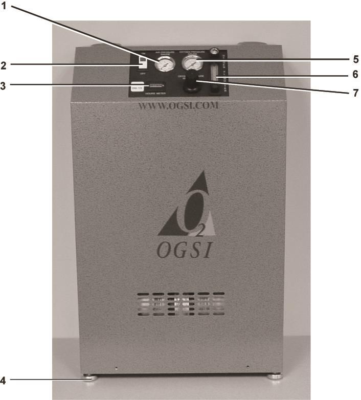
The Return Authorization Number must be visibly written on the outside of the package
of the returned Products, component parts or equipment as applicable or OGSI will not
accept the return.

Note: A Credit Certificate will be created for all Warranty Exchange transactions.
OGSI will provide the Credit Certificate with an invoice at the time of shipment to the
original user. The Credit Certificate must be included in the package to OGSI with the
returned products within 30 days of the date of the invoice. Failure to return Warranty
Exchange Products to OGSI within 30 days will make the Warranty Exchange process void
and payment for Products will be billed and due on receipt.

Note: The warranties of OGSI as set forth herein shall also become null, void and not
binding on OGSI if a defect or malfunction occurs in the Products or any part of the
Products as a result of:
    a) A failure to provide the Required Operating Conditions for the Products
       (See page 35)
    b) Repair, attempted repair, adjustment or servicing of the Products, or any
       component parts or equipment that constitutes part of the Products by anyone
       other than an authorized representative of OGSI. The authorized service
       representative must obtain prior approval from OGSI’s Service Manager before
       performing any warranty work.
    c) External Causes (e.g. flood, hurricane, tornado, fire, any natural disaster, or any
       event deemed an act of God).

Molecular Sieve Replacement:
       The breakdown of the molecular sieve inside the generator (dusting of the sieve)
only occurs if excess water/oil is entrained in the feed air stream. Under no
circumstances is the molecular sieve covered under any warranty by OGSI. If sieve
dusting occurs on your machine, check the air compressor, air dryer and filter elements.

Other Matters:
       OGSI is not liable for any special, indirect, punitive, economic, incidental or
consequential losses or damages including without limitation, loss of use, malfunction of
OGSI products, replacement oxygen charges, delays or lost savings related to the
Products or otherwise even if OGSI shall have been advised of the possibility of such
potential losses or damages.

                             Limits of Liability
        OGSI Oxygen Generator products shall not be used for breathable or medical
oxygen applications, unless they are assembled with the appropriate support equipment,
tested, and operated in compliance with either American, Canadian or ISO norms for
hospital oxygen systems.

Effective 07/2014                                                                    4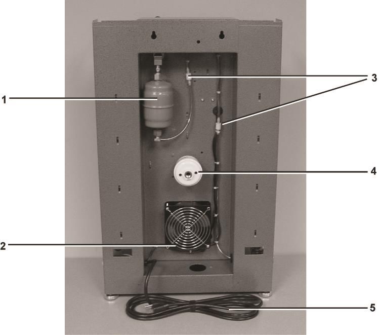
Safety Guidelines
Unpacking
ADDITIONAL PACKAGING MATERIAL INSIDE THE UNIT MUST BE REMOVED AND THE AIR INLET
FILTER MUST BE INSTALLED PRIOR TO OPERATING THE OXYGEN GENERATOR.
Ensure that the unit is NOT connected to an electrical outlet.
Remove the six (6) screws with nylon washers located on the front and both sides of the unit.
Lift the front cover up and away from chassis.
Remove packaging material from top, behind, and under the air compressor (drawing below).
Install air inlet filter (on top of the air compressor as shown below).
Install the front cover and secure the six (6) screws with nylon washers.
Air Inlet Filter
REMOVE
PACKAGING
MATERIAL.
FAILURE TO DO SO
WILL VOID YOUR
WARRANTY.
UNIT SHOWN WITH COVER REMOVED
Effective 07/2014 5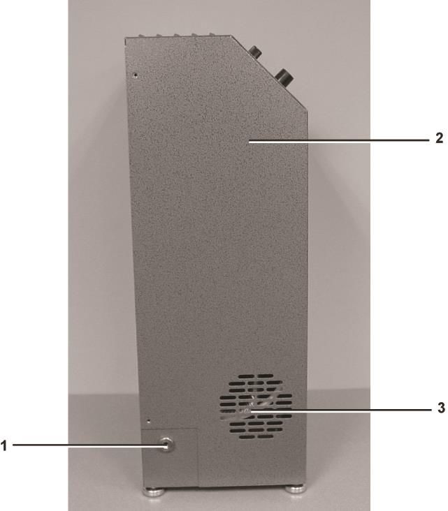
Operating

 OGSI Oxygen Generators are self-contained systems for the production of high purity
 oxygen. Although oxygen itself is not combustible, it can be very dangerous. It greatly
 accelerates the burning of combustible materials.

Precautions should be taken to avoid a fire in the area of the oxygen generator.

Smoking should not be permitted in the area where the oxygen generator is located.

All oxygen connections and hoses should be kept clean and free of grease, oil and other combustible
materials.

Valves controlling oxygen flow should be opened and closed slowly to avoid the possibility
of fires or explosions.

Do not attempt to modify or enhance the performance of an oxygen generator in any way.

When bleeding a tank or line, stand clear and do not allow oxygen to embed itself within clothing.
A spark could ignite the clothing violently.

Effective 07/2014                                                                  6
Product Information
Features and Applications
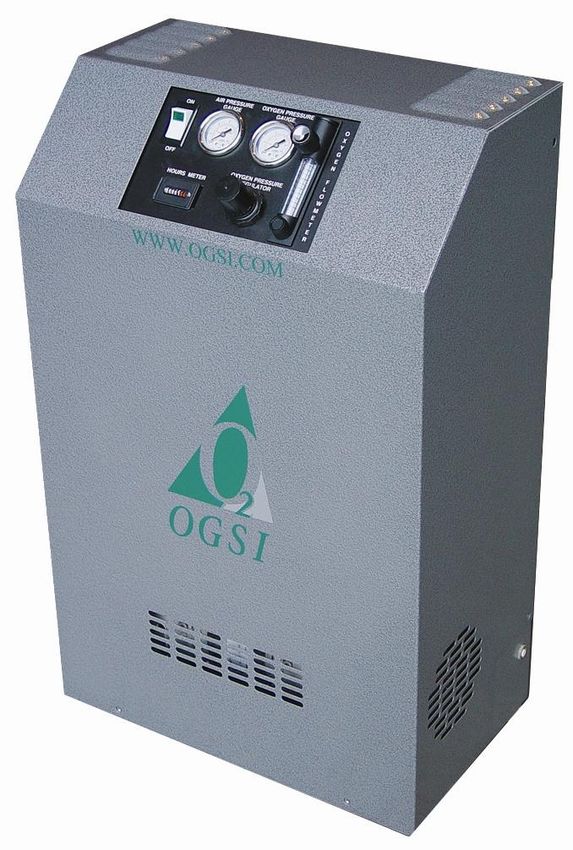
The OGSI Models OG-15 and OG-20 extract oxygen from the atmosphere using
Pressure Swing Adsorption (PSA) technology. It concentrates oxygen up to
93% (± 3%) purity which can be utilized in many applications.
Features
Easy to Use
Just connect to an electrical outlet, push the ON/OFF power switch to the ON
position and set your desired flow and pressure.
Dependable
Its internal air compressor, filtration system, Zeolite sieve, storage tank, and flow
control system are designed for 24/7operation.
Durable
Built on a powder coated steel chassis, its anodized aluminum sieve beds are
fitted with custom aluminum end caps for years of reliable service.
Portable
The OG-15 weighs 65 lb (29 kg) without cover and the OG-20 weighs
67 lb (30 kg) without cover. These units are industrial strength oxygen
generators.
Safe
A built-in oxygen pressure regulator allows you to set the delivery pressure
according to your requirements. The compressor on the OG-15 and OG-20
has 0.33 hp and has a built-in safety relief valve to prevent pressures above
55 psi (3.8 bar). The OG-15 and OG-20 units deliver an optimal flow of
oxygen up to 12 psi (0.83 bar) and 20 psi (1.4 bar) respectively.
Economical
Oxygen is free! The OG-15 and OG-20 eliminate the unnecessary costs involved
in transportation, storage and cylinder rental. The OG-15and OG-20use less than
0.7 kW of electricity to deliver up to 15 ft3and 20 ft3of oxygen per hour
respectively. This product is both cost-effective and energy-efficient.
Effective 07/2014 7Applications The OG-15 and OG-20 can be used in various applications. A few examples are given below. Hyperbaric Oxygen Therapy (HBOT) Fish Farming and Aquaculture Ornamental Glass Manufacturing Jewelry Manufacturing Bottled Water Manufacturing Waste and Water Treatment Effective 07/2014 8
Pressure Swing Adsorption (PSA) Technology
                  An OGSI Oxygen Generator is an on-site oxygen generating machine capable of
          producing oxygen on demand in accordance with your requirements. In effect, it separates
          the oxygen (21%) from the air it is provided and returns the nitrogen (78%) to the
          atmosphere through a waste gas muffler. The separation process employs a technology
          called Pressure Swing Adsorption (PSA). At the heart of this technology is a material
          called Molecular Sieve (Zeolite).This sieve is an inert, ceramic-like material that is designed
          to adsorb nitrogen more readily than oxygen. Each of the two beds that make up the
          generator contains this sieve. The process is described below.

Stage 1
                                                          Stage 2
Compressed air is fed
                                                          When the sieve in the
into the first molecular
                                                          first bed becomes full
sieve bed. Nitrogen is
                                                          of nitrogen, the airflow
trapped, while oxygen
                                                          is then directed into
is allowed to flow
                                                          the second bed.
through.

Stage 3                                                   Stage 4
As the second bed                                         Compressed air is once
separates the oxygen                                      again fed into the first
from the nitrogen, the                                    bed and the process is
first bed vents its                                       repeated continuously.
nitrogen into the                                         A constant flow of
atmosphere.                                               oxygen is produced.

                  This air separation process is reliable and virtually maintenance-free.
          The molecular sieve will last indefinitely, as long as it does not become contaminated
          with water or oil vapors. This is why regular filter element replacement is crucial to
          trouble-free operation. The filter elements are very inexpensive and require semi-annual
          maintenance.

          Effective 07/2014                                                                   9
External Components
Front View
1. Air Pressure Gauge
2. ON/OFF Power Switch
3. Hours Meter
4. Anti-vibration Feet (Optional)
5. Oxygen Pressure Gauge
6. Oxygen Flow Meter
7. Oxygen Pressure Regulator
Effective 07/2014 10Control Panel (Magnified View)
1. ON/OFF Power Switch
2. Model Number
3. Oxygen Flow Meter Knob
4. Oxygen Pressure Regulator Knob
Effective 07/2014 11Side Views
Left Right
1. Vent Hole (8” minimum clearance) 1. Oxygen Outlet
2. Cabinet 2. Cabinet
3. Reset Button 3. Vent Hole (8” minimum clearance)
4. Voltage Label
Effective 07/2014 12External Components Description
This gauge indicates the air pressure being delivered by the internal air
Air Pressure Gauge compressor to the sieve beds. It should vary between 30-45 psi (2.1-3.1 bar)
while the unit is operating.
This switch controls power to the machine. It is lighted when the machine
ON/OFF Power Switch switch is in the ON position.
The hours meter shows how long the unit has been operating. This helps
Hours Meter indicate when service intervals are due.
This gauge indicates the pressure at which the oxygen is being delivered.
The flow meter is calibrated at 12 psi (0.83 bar) for OG-15 and 20 psi (1.4
Oxygen Pressure Gauge bar) for OG-20 and the pressure must be adjusted to this level when reading
the flow meter. The oxygen regulator can adjust the pressure.
The regulator controls the oxygen delivery pressure level. To adjust the
oxygen delivery pressure level, pull the adjustment knob easily towards
you. Turning it clockwise increases the delivery pressure while turning it
Oxygen Pressure Regulator counter-clockwise decreases the delivery pressure. The oxygen pressure
gauge will indicate the level set. To lock it into place, push down the
adjustment knob.
Vent Holes These vent holes allow cooling air to enter and exit the enclosure.
The reset button is actually a circuit breaker that opens if there is an electrical
Reset Button overload in the system and/or if there is any back pressure within the air
and/or oxygen lines.
This fitting is a ‘B’ size oxygen adapter. It can be removed to expose a 1/8”
Oxygen (O2) Outlet
female NPT pipe fitting.
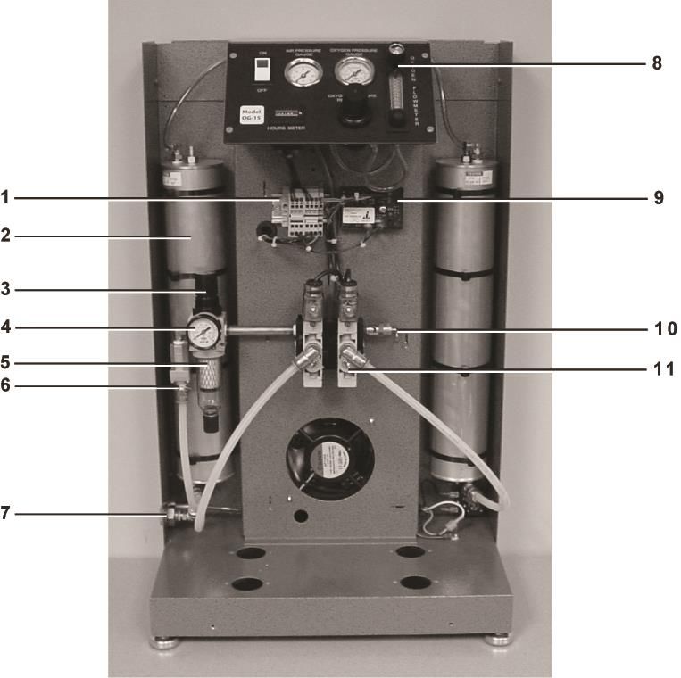
Effective 07/2014 13Internal Components (OG-15)
Front View
1. Control Panel
2. Terminal Assembly Strip
3. Sieve Bed
4. Heat Exchanger
5. Air Compressor
6. Circuit Board
7. Pre-filter
8. Valve Block (115 VAC or 230 VAC)
9. Inlet Air Filter
10. Safety Relief Valve (55 psi)
Effective 07/2014 14Back View (Standard)
1. Oxygen Receiver Tank
2. Cooling Fan (115 VAC or 230 VAC)
3. Capacitor
4. Power Cord
5. Vent Holes
6. Purge Loop
7. Check Valves
8. Exhaust Muffler
9. Serial Number Locator (Not Visible)
Effective 07/2014 15Back View (Quiet Muffler Option)
1. Oxygen Receiver Tank
2. ½” Female Elbow
3. ¼” Foam Filter
4. Exhaust Muffler
5. ½”x ¼” Reducing Nipple
Effective 07/2014 16Internal Components (OG-15E Compressor-less)
Front View
1. Terminal Assembly Strip
2. Sieve Bed
3. Regulator Adjustment Knob
4. Inlet Pressure Gauge
5. Filter Regulator
6. Inlet Check Valve
7. Compressed Air Inlet
8. Control Panel
9. Circuit Board
10. Safety Relief Valve
11. Valve Block (115 VAC or 230 VAC)
Effective 07/2014 17Back View
1. Oxygen Receiver Tank
2. Cooling Fan (115 VAC or 230 VAC)
3. Check Valves
4. Exhaust Muffler
5. Power Cord
Effective 07/2014 18Internal Components (OG-20)
Front View
1. Control Panel
2. Terminal Assembly Strip
3. Sieve Bed
4. Heat Exchanger
5. Air Compressor
6. Circuit Board
7. Sieve Bed
8. Pre-Filter
9. Valve Block (115 VAC or 230 VAC)
10. Inlet Air Filter
11. Safety Relief Valve (55 psi)
Effective 07/2014 19Back View
1. Oxygen Receiver Tank
2. Cooling Fan (115 VAC or 230 VAC)
3. Capacitor
4. Power Cord
5. Vent Holes
6. Purge Loop
7. Check Valves
8. Exhaust Muffler
9. Serial Number Locator (Not Visible)
Effective 07/2014 20Internal Components (OG-20E Compressor-less)
Front View
1. Terminal Assembly Strip
2. Sieve Bed
3. Regulator Adjustment Knob
4. Inlet Pressure Gauge
5. Filter Regulator
6. Inlet Check Valve
7. Compressed Air Inlet
8. Control Panel
9. Circuit Board
10. Safety Relief Valve (55 psi)
11. Valve Block (115 VAC or 230 VAC)
Effective 07/2014 21Back View
1. Oxygen Receiver Tank
2. Cooling Fan (115 VAC or 230 VAC)
3. Check Valves
4. Exhaust Muffler
5. Power Cord
Effective 07/2014 22Internal Components Description
Terminal Assembly The terminal strip distributes electrical power as required to the compressor and
Strip control components of the machine.
These beds contain the molecular sieve that performs the air separation process.
Sieve Beds They are spring loaded to prevent settling and should not ever need to be opened. If
the sieve becomes contaminated, the beds can be easily replaced.
The heat exchanger (Delta Twist) is positioned in front of the cooling fan and
delivers the feed air from the air compressor to the valve block. Using this
Heat Exchanger
proprietary tube design, significant air temperature reduction occurs before the air
enters the sieve beds, improving overall performance.
The air compressor supplies the feed air to the sieve beds. It is held in place by four
bolted rubber feet and can be easily replaced when necessary. It should work as
Air Compressor
designed for a minimum of 10,000 hours and will last 20,000 hours in
many cases.
The circuit board controls the operation of the flow controlling valves. While one
Circuit Board
valve coil is energized, the other is not.
The valve block holds the main valves that control the direction of airflow in the
machine. These are the feed and waste valves for each bed. They direct feed air to
Valve Block
each bed during oxygen production and waste nitrogen through the muffler to
regenerate the sieve. The cycle continues while the unit operates.
The air filter keeps dust and dirt from entering the compressor and needs to be
Inlet Air Filter changed twice a year in normal environments to maintain the unit’s performance. It
should be changed more often in dirty, oily areas.
This valve is in place to ensure that the oxygen sieve tank does not exceed maximum
Safety Relief Valve pressure. It will only open in the event of a serious malfunction.
The cooling fan is used to draw air into the unit and to remove heat from the
Cooling Fan
compressor. The fan runs while the unit operates.
The power cord used on 115 VAC/60 Hz electrical systems comes with a three-
Power Cord pronged ground fault protected plug. For 230 VAC, a plug of local
configuration will need to be installed by the end-user.
Vent Holes These vent holes allow cooling air to enter the enclosure.
The exhaust muffler is used to silence the exhaust noise that occurs as a result of the
sieve beds rapidly depressurizing to atmospheric pressure, releasing nitrogen. For
Exhaust Muffler
installations where a lower noise level is required, OGSI offers an optional
alternative muffler system that can decrease the emitted noise even further.
Air Regulator
(OG-15E and OG-20E The air regulator controls the air pressure going into valve block.
Compressor-less)
Effective 07/2014 231 INLET AIR FILTER
Effective 07/2014
2 FEED AIR COMPRESSOR
3 RELIEF VALVE
4 HEAT EXCHANGER
5 AIR PRESSURE GAUGE
6 LEFT VALVE
7 RIGHT VALVE
8 NOISE MUFFLER
9 LEFT PURGE ORIFICE
10 RIGHT PURGE ORIFICE
11 CHECK VALVE
12 OXYGEN RECEIVER TANK
13 PRESSURE REGULATOR
14 OXYGEN PRESSURE GAUGE
15 OXYGEN FLOW METER
16 FLOW CONTROL VALVE (KNOB)
Process Flow Schematic: OG-15 and OG-20
24Effective 07/2014
1 INLET AIR FILTER
2 N/A
3 RELIEF VALVE
4 N/A
5 AIR PRESSURE GAUGE
6 LEFT VALVE
7 RIGHT VALVE
8 NOISE MUFFLER
9 LEFT PURGE ORIFICE
10 RIGHT PURGE ORIFICE
11 CHECK VALVE
12 OXYGEN RECEIVER TANK
13 PRESSURE REGULATOR
14 OXYGEN PRESSURE GAUGE
15 OXYGEN FLOW METER
16 FLOW CONTROL VALVE (KNOB)
25
Process Flow Schematic: OG-15E and OG-20E (Compressor-less)Process Flow Description
The normal flow of air through the OG-15/OG-20 and OG-15E/OG-20E
(Compressor-less) units is shown on the previous pages in the Process Flow Schematic
Drawings. As you can see, once the incoming air is filtered and compressed in the
OG-15/OG-20 unit or regulated to the proper pressure in the OG-15E/OG-20E
(Compressor-less) unit, it is directed into one of the two sieve beds. As the air enters the
bed, the nitrogen is adsorbed by the sieve and the oxygen passes through as product gas
to the storage tank. Each bed produces oxygen until the sieve in that bed is saturated with
nitrogen. When this occurs, the feed airflow is directed to the other bed, which continues
the production process. While the second bed is producing oxygen, the first bed is
releasing into the atmosphere the nitrogen it adsorbed, under very low pressure through a
waste gas muffler.
From the storage tank, the oxygen pressure regulator and the flow meter can be
used to set the oxygen delivery pressure and the oxygen flow rate. While it is possible to
set either of these parameters to the maximum levels, they cannot both be maximized at the
same time. Pressure, flow rate and oxygen purity are all interrelated properties. Any
attempt to increase pressure or flow rate will cause a decrease in one (or both) of the
remaining two properties. The rated production capacity of this machine is 15 SCFH (0.4
Nm3/h) or 7 LPM at 12 psi (0.83 bar) for OG-15and 20 SCFH (0.5 Nm3/h) or 10 LPM at
20 psi (1.4 bar) for OG-20. Oxygen purity will suffer in any overdraw conditions.
Effective 07/2014 26Unit Specifications: OG-15
Performance
15 SCFH @ 12 psi
Oxygen Volume
7 LPM or 0.4 Nm3/h @ 0.83 bar
Oxygen Pressure
OG-15 1 – 12 psi (0.83 bar)
OG-15E (Compressor-less) 1 – 12 psi (0.83 bar)
Oxygen Purity 93% (± 3%) [See Graphs, Pages 31-32]
Oxygen Dew Point - 60° F (-51°C)
Feed Air Requirement
OG-15 None, compressor included
OG-15E (Compressor-less) 4 SCFM @ 30-45 psi (6.3 Nm3/h @ 2.1-3.1 bar) minimum
Approximately 2 minutes to attain maximum purity after initial
Response Time
start-up or extended shut-down
Physical
Oxygen Outlet Fitting B Size oxygen adapter
Air Inlet Fitting
OG-15 None
OG-15E (Compressor-less) 1
/4” FNPT Bulkhead
Sound Levels
OG-15 68 dBA @ 1 m without cover
65 dBA @ 1 m with cover
55 dBA @ 1 m with reduced noise option
OG-15E (Compressor-less) 35 dBA @ 1 m
Dimensions 17 x 10 x 28 in (W x D x H)
43 x 25 x 71 cm (W x D x H)
Weight
OG-15 65 lb (30 kg) without cover
78 lb (35kg) with cover
OG-15E (Compressor-less) 40 lb (18 kg) without cover
53 lb (24 kg) with cover (optional)
Effective 07/2014 27Continued from Page 27
Power Requirement
OG-15
Standard (Domestic) 115 VAC, 60 Hz, Single Phase 6.0 A
Optional (International) 230 VAC, 50/60 Hz, Single Phase, 3A
OG-15E (Compressor-less)
Standard (Domestic) 115 VAC, 60 Hz, Single Phase, 0.2 A
Optional (International) 230 VAC, 50/60 Hz, Single Phase, 0.1 A
Effective 07/2014 28Unit Specifications: OG-20
Performance
20 SCFH @ 20 psi (1.4 bar)
Oxygen Volume
10 LPM or 0.5 Nm3/h @ 1.4 bar
Oxygen Pressure
OG-20 1 – 20 psi (1.4 bar)
OG-20E(Compressor-less) 1 – 20 psi (1.4 bar)
Oxygen Purity 93% (± 3%) [See Graphs, Pages 31-32]
Oxygen Dew Point - 60° F (-51 °C)
Feed Air Requirement
OG-20 None, compressor included
OG-20E(Compressor-less) 4.9 SCFM @ 30 – 45 psi (7.7 Nm3/h @ 2.1-3.1 bar)
Approximately 2 minutes to attain maximum purity after initial
Response Time
start-up or extended shut-down
Physical
Oxygen Outlet Fitting B Size oxygen adapter
Air Inlet Fitting
OG-20 None
OG-20E(Compressor-less) 1
/4” FNPT Bulkhead
Sound Levels
OG-20 68 dBA @ 1 m without cover
65 dBA @ 1 m with cover
55 dBA @ 1 m with reduced noise option
OG-20E (Compressor-less) 35 dBA @ 1 m
Dimensions 17 x 10 x 28 in (W x D x H)
43 x 26 x 71 cm (W x D x H)
Weight
OG-20 67 lb (30 kg) without cover
80 lb (36 kg) with cover
OG-20E(Compressor-less) 40 lb (18 kg) without cover
53 lb (24 kg) with cover (optional)
Continued
Effective 07/2014 29Continued from Page 29
Power Requirement
OG-20
Standard (Domestic) 115 VAC, 60 Hz, Single Phase 6.0 A
Optional (International) 230 VAC, 50/60 Hz, Single Phase, 3.0 A
OG-20E(Compressor-less)
Standard (Domestic) 115 VAC, 60 Hz, Single Phase, 0.2 A
Optional (International) 230 VAC, 50/60 Hz, Single Phase, 0.1 A
Effective 07/2014 30Performance Curves
Oxygen Purity vs. Flow
OG-15
OXYGEN PURITY (± 3%)
OXYGEN PURITY (%)
OXYGEN FLOW RATE (SCFH)
OG-15 E Compressor-less
OXYGEN PURITY (± 3%)
OXYGEN PURITY (%)
OXYGEN FLOW RATE (SCFH)
Effective 07/2014 31OG-20
OXYGEN PURITY (± 3%)
OXYGEN PURITY (%)
OXYGEN FLOW RATE (SCFH)
OG-20 E Compressor-less
OXYGEN PURITY (± 3%)
OXYGEN PURITY (%)
OXYGEN FLOW RATE (SCFH)
NOTE: SCFH (Standard Cubic Foot per Hour) gas measured at 1 atmosphere
and 70 °F and 0% humidity.
Effective 07/2014 32Safety Precautions It is very important that you read the precautions below and make yourself aware of the hazards of oxygen in general. While it can be handled and used very safely, it can also be mishandled or applied incorrectly causing dangerous situations. Oxygen is a fire hazard. It can be very dangerous as it vigorously accelerates the burning of combustible materials. To avoid a fire and/or the possibilities of an explosion; oil, grease or any other easily combustible materials must not be used on or near the oxygen generator. DO NOT SMOKE NEAR THE UNIT. The unit should be kept away from heat and open flames. Individuals who have experience handling oxygen systems should become the designated operators of the oxygen generator within your facility. In crucial applications, it is important to have a backup supply of oxygen since the generator does not come with any reserve storage tank and requires electrical power to operate. Therefore, during power outages, oxygen will not be produced. Do not use extension cords to bring power to the generator. The current drawn into the unit is high and could overheat some extension cords. It is also important to use only a properly grounded electrical outlet. High pressure oxygen may present a hazard. Always follow proper operating procedures, and open valves slowly. Rapid pressurization may result in operator/user injury. Safety glasses and hearing protection are required when venting oxygen under high pressure. Ensure that the oxygen outlet stream is not directed toward anyone’s clothing. Oxygen will embed itself in the material and one spark or hot ash from a cigarette could violently ignite the clothing. Effective 07/2014 33
Pre-Installation
Before installing the OGSI Oxygen Generator, it is necessary to consider the
location, space available and power supply for the generator.
1) Locating the OG-15/OG-20:
The oxygen generator should be located in an area that is indoors and remains
between 40F (5C) and 100F (38C). Setting up the machine outdoors or
in an area that is not normally within this temperature range will void the
OGSI Warranty.
There should also be a distance of at least 8 in (20 cm) between the unit and
any side wall in the room that it will be located in. This is to ensure that
airflow into the machine through the cooling fans is not restricted.
(OG-15E/OG-20E Compressor-less Only) The machine must be located
within reach of an air supply line, as this machine requires an external pre-
existing source of pressurized air.
2) Space Available for the OG-15/OG-20:
If the OG-15/OG-20 unit is going to be set up in a room that is small, (less than
1000 ft3or 28.3 m3), that room should be well ventilated (at least 5 air changes
in the room per hour). The oxygen generator will be discharging nitrogen into
the atmosphere of the room and a nitrogen build up could be dangerous to
people entering the room. If the generator is placed in a small closet, the air in
that closet will become enriched with nitrogen. As the oxygen generator
continues to operate, it would become more and more difficult for it to separate
the oxygen from the air because oxygen will make up a smaller and smaller
fraction of the air that is fed into the oxygen generator.
3) Power Supply for the OG-15/OG-20:
The oxygen generator should be positioned within 8 ft (2.2 m) of the electrical
outlet that will power it. The reason for this is that the motor draws a large
current during the first few seconds of start-up. It is also very important for
this reason NOT to use any extension cords with the unit. They could
overheat and melt, possibly causing a fire. The electrical outlet system to
which the OGSI oxygen generator is connected should be used exclusively for
that purpose and no other electrical appliances should be connected to it.
Effective 07/2014 34Required Operating Conditions
Location of Machine:
This standard oxygen generating system is intended for use indoors in a commercial
or light industrial setting. The enclosure meets NEMA12 protection guidelines, which
provides a degree of protection against dust, falling dirt and non-corrosive liquids.
Feed Air/Ambient Air Quality:
The life of any PSA oxygen generator is directly related to the air quality that is
fed into it. Hot, humid, dirty, oily air deteriorates and degrades the performance of the
molecular sieve. In order to preserve the effectiveness and extend the life of the oxygen
generator, precautions must be taken to ensure that the air provided is cool, dry, clean and
oil-free.
Changing the inlet air filter is a simple and easy way to provide the unit with some
protection. It is advisable to operate the unit in an air-conditioned or a well-ventilated area.
The room should also be free of toxic gases and high concentrations of hydrocarbons,
especially carbon monoxide. Humid, oily areas should be avoided as installation sites as
much as possible.
Ambient Air Temperature:
The machine is designed for use over a temperature range of 40F to 100F (5C to
38C). Since hot air has the ability to hold more water in the form of humidity than cool air,
operating the unit in hot areas will reduce the effective life of the molecular sieve.
Note: Operation outside of this temperature range will not be warranted by OGSI.
Electrical Power:
On U.S. models, the power for the control circuitry of the oxygen generator is a
single-phase electrical supply of 115 VAC and about 6 A at a frequency of 60 Hz.
This equates to approximately 700 W of power. It is required that a 10 A circuit
be dedicated to each OG-15/OG-20 unit. Additionally, the unit must be connected to
this circuit using only the supplied power cord, and without the use of additional
extension cords.
Feed Air Requirements (OG-15ECompressor-less Only):
An incoming air pressure of 4 SCFM or 6.3 Nm3/h for OG-15 and 4.9 SCFM or
7.7 Nm3/h for OG-20 at 30-45 psi (2.1–3.1 bar) is required for proper functioning of this
machine. The air should be cool, dry and clean, filtered to remove any contaminants such
as dust particles and moisture. It is recommended that it meet the requirements of
ISO8573.1 Class 1.4.1.
Positioning:
The unit must be operated in an upright position only, with no obstruction
blocking airflow around the unit.
Effective 07/2014 35Set-up & Installation Although every OG-15/OG-20unit is thoroughly tested and checked before it is shipped from our facility, the following steps are necessary to ensure that none of the internal components have been damaged during shipment. This check should take less than five minutes to perform. (Refer to ‘Initial Inspection’ on page 2 and ‘Unpacking Instructions’ on page 5 before reading the instructions below) Make a visual inspection of the machine and make sure all parts are properly connected. (Refer to ‘Components’ section) Connect the unit into a grounded electrical outlet. A receptacle plug of local configuration will need to be attached first if the machine has been shipped outside North America. Push the ON/OFF green lighted power switch to the ON position and make sure that the green light is illuminated. Listen for the sound of the compressor to start operating. If you do not hear it within a few seconds, shut the machine down immediately and call OGSI for assistance. Once the machine is operating, turn the knob on the upper part of the oxygen flow meter to adjust the oxygen flow to 7 LPM (0.4 Nm3/h) for OG-15 and 10 LPM (0.5 Nm3/h) for OG-20. The ball in the flow meter should be in the middle of the flow meter indicating 7 LPM or 10 LPM flow for OG-15 and OG-20 respectively. The oxygen pressure gauge should read 12 psi (0.83 bar) or 20 psi (1.4 bar) for OG-15 and OG-20 respectively. If it does not, turn the oxygen regulator either clockwise to increase the pressure or counter-clockwise to decrease it until it reaches 12 psi (0.83 bar) or 20 psi (1.4 bar) for OG-15 and OG-20 respectively. You should be able to feel oxygen being discharged from the lower left oxygen outlet port. If these things do not occur, check to make sure that none of the hose connections have come loose. Call the OGSI Technical Service Department at (800) 414-6474 (toll free number in USA and Canada) or (716) 564-5165 if no loose connections are found and trouble persists. Effective 07/2014 36
Operating Instructions
   Start-up
   Once the system has been installed in accordance with the set-up and installation
   instructions, it may be operated. The following steps should provide some direction.
   Please keep in mind that this system produces medical-grade oxygen conforming to
   the standards of USP (United States Pharmacopeia XXII oxygen 93% Monograph)
   however, the system is not intended to be used as a medical device.

  Connect the oxygen outlet to the application.

  After connecting it to an electrical outlet and pushing the switch on the machine to the ON
  position, wait for 2 minutes for the unit to come up to maximum purity.

  The oxygen delivery pressure should be set to 12 psi (0.83 bar) for OG-15 and 20 psi (1.4 bar)
  for OG-20.

  Open the flow meter to the desired level of flow as indicated by the ball float inside the
  flow meter.

  Begin using the oxygen.

Shut-down

  To temporarily stop the flow of oxygen from the unit; simply close the valve on the flow
  meter by turning the knob at the base, clockwise to zero (0).

  To shut off the machine, push the ON/OFF power switch to the OFF position. The light should
  go out on the switch and the compressor noise should quickly die out.

Effective 07/2014                                                                    37
Troubleshooting Guide
Problem Sign Cause Solution
Dusting of Sieve Beds White powder visible Contaminated sieve Repack the sieve beds.
in the machine or very Moisture in air Clean valves and mufflers.
high air pressure levels Make sure dry air is being
fed to the machine.
Valves Sticking Air pressure levels Dusting of sieve or Remove valve block from
too high machine filled with dirt machine and clean valves
and dust due to air and spools completely.
filters not being
replaced
Pressure Switch not Machine not turning Faulty switch Remove switch and return
functioning ON/OFF at target for replacement.
pressures
Warning Signs:
Low Oxygen Pressure This may be a result of a leak in the system.
Use a leak testing solution to locate and repair any
air leaks.
The machine has run for 30 minutes and purity has This may be a result of a leak in the system.
not yet been reached Use a leak testing solution to locate and repair any
air leaks.
Oxygen purity has fallen below acceptable limits This may be an indication of a leak within the system.
Use a leak testing solution to locate and repair any leaks.
Effective 07/2014 38Preventive Maintenance Air Filter Element Replacement: The air filter element provided with the OG-15/OG-20 must be replaced every six (6) months on an average. This element helps to maintain the quality of the feed air supply and preserve the molecular sieve inside the oxygen generators. For the OG-15E/ OG-20E (Compressor-less) unit, the filters used on your own air compressor must be replaced as often as necessary to maintain proper feed air quality. (Contact the manufacturer of your compressor for recommended service intervals.) Failure to replace the filter element on schedule will result in the warranty becoming invalid. Cabinet & Power Cord: The cabinet and power cord should be occasionally washed down with a sponge or clean rag and some soapy water. Avoid the use of ammonia or other strong chemical based cleaning solvents. This prevents dust and dirt from building up on the machine. Air Compressor (OG-15/OG-20 Only): You should consider your air compressor an important part of your oxygen generating system. In addition to changing the air filter element, maintenance is relatively simple. The fans on either end should remain free of debris/dust. The air compressor should last five (5) or six (6) years or longer under normal operating conditions. Eventually, however, it will need to be re-built or replaced. Oxygen purity and flow rate along with feed air pressure delivered to the sieve beds will all be indicators that the air compressor has expended its life. Replacement in the field is possible, but returning the unit to OGSI or an authorized service center is recommended. Valve Replacements: The best method to address this issue is to return the unit to OGSI or to an authorized service center for repair. Effective 07/2014 39
Technical Service Assistance
It is our intention to provide complete customer satisfaction. This manual is one
way in which we hope to provide you with technical assistance.
If you do not find what you need in this manual or you have other questions about
this equipment, please feel free to contact us directly. We look forward to serving your
oxygen needs and invite your inquiries. We will respond to you as promptly as possible.
You can reach OGSI through the following means:
By Telephone (Within the United States and Canada):
(800) 414-6474 - Our toll free number (Within USA and Canada only)
(716) 564-5165 - Our direct number
By Telephone (Outside the United States):
Your local International Access Code (usually 0 or 00), followed by
The Country Code for the U.S. which is (1), followed by our Area Code and
Number (716) 564-5165
By Automated Voicemail:
(716) 564-5165
By Fax (Within or outside the United States):
(716) 564-5173
By E-Mail or Website:
ogsimail@ogsi.com
http://www.ogsi.com
By Mail:
OGSI
814 Wurlitzer Drive
North Tonawanda, New York 14120 USA
By UPS, FedEx or Common Carrier: (Address to return shipments)
OGSI
814 Wurlitzer Drive
North Tonawanda, New York 14120 USA
Technical service personnel are available from 8:00 AM to5:00 PM EST (GMT - 5).
We also have a list of Distributors and Authorized Service Agents available upon request.
Customer Satisfaction Survey
Help us serve you better. Please take our Customer Satisfaction Survey at www.ogsi.com
Effective 07/2014 40Appendix Effective 07/2014
Page left intentionally blank
OG-15/OG-20
                              CERTIFICATE OF COMPLIANCE

GENERATOR/TESTING INFORMATION

Technician_________________________ Serial No. /Mod______________________ Date___/___/___

Hours____       Purity____%   Regulated Air Pressure: Low____ High____   Outlet Pressure_____ psi

Flow Meter Setting_____ SCFH Voltage 110V □ 220V □ Temperature_____ °F         Humidity_____%

QUALITY CONTROL INFORMATION

                              PASSED                                             PASSED

 Flow Meter & Fittings                             Regulator & Fittings
 Upper Bulkhead                                    Left Side Sieve Bed
 Gauges & Fittings                                 Top Elbow
 Valve Block/Valves                                Top Quad Seal
 Barbed Orifice                                    Bottom Elbow
 Side Plugs                                        Bottom Quad Seal
 Front Plugs                                       Right Side Sieve Bed
 Elbows                                            Top Elbow
 Compressor                                        Top Quad Seal
 Plug                                              Bottom Elbow
 Street Elbow                                      Bottom Quad Seal
 Prestolok Elbow                                   Product Tank
 Safety Valve                                      Top
 Purge Loop/O2 Out                                 Bottom
 Orifices                                          Bottom Bed Tubes
 Barbed Tee                                        Secure
 Check Valves                                      Not Touching Components

TESTING COMMENTS:-
_________________________________________________________________________________
_________________________________________________________________________________
_________________________________________________________________________________
_________________________________________________________________________________

PACKING CHECKLIST

Sieve Beds:
Miscellaneous:
Machine Labels:
Compressor Foam:
Shipping Box Labels:
Special Instructions:

Effective 07/2014                                                                           I
Page left intentionally blank
Spare Parts List
                                                    OG-15

                        PART NAME                           PART NUMBER          QUANTITY
Strain Relief for Power Cord                                  1820018-001           1
Reset Button                                                  1830002-001           1
ON/OFF Lighted Switch                                         1840001-004           1
Timer 115 VAC/230 VAC                                         1850001-001           1
Hours Meter 115 VAC                                           1870002-002           1
Hours Meter 230 VAC                                          1870002-003            1
Valve Wire Harness (each) 115 VAC                            1880011-002            2
Valve Wire Harness (each) 230 VAC                            1880011-003            2
Power Cord (with 3-Prong Plug)                               1890001-001            1
Cord Set for Fan (115 VAC/230 VAC)                           1890003-001            1
Compressor Mounts-Diamond Plate (starting w/2000)            1460001-002            4
Inline Check Valves                                          1530001-B01            2
1
 /4” Safety Relief Valve-55#                                 1540001-C01            1
Exhaust Muffler                                              1700001-C02            1
Thomas Compressor Rebuild Kit                                2114001-T01            1
Inlet Fan 115 V                                              2140001-001            1
Inlet Fan 230 V                                              2140001-002            1
Heat Exchanger                                               2140020-001            1
Oxygen Pressure Regulator                                    2150002-025            1
11/2”,0-12 psi Dial Gauge, Oxygen Pressure                   2190001-LB1            1
11/2”,0-60 psi Dial Gauge, Air Pressure                      2190001-LB2            1
Oxygen Flow Meter                                            2700001-002            1
Solenoid Valve Assembly 115 VAC                              7020001-002            1
Solenoid Valve Assembly 230 VAC                              7020002-002            1
Thomas Compressor Assembly (115 VAC, 60 Hz)                  7030001-001            1
Thomas Compressor Assembly (230 VAC, 50 Hz)                  7030002-001            1
Oxygen Receiver Tank Assembly                                7050001-001            1
OEM Oxygen Receiver Tank Assembly                            7050002-001            1
1
 /4”Green Oxygen Tubing - Per Foot                           2210004-C01            3
3
 /8” Poly Tubing - Per Foot                                  2210003-D02            2
Purge Loop Assembly                                          7040001-001            1
Anti-Vibration Feet                                          1460001-003            4
Inlet Air Filter (Change every six months)                   2160001-C01            2
Black Filter for Quiet Muffler Option                        2160001-C02            2
Casters                                                      2530005-001            4
Replacement Set of Sieve Beds w/ cable ties                  7060001-001            1
Complete Instrument Panel-115 VAC                            7070001-H01            1
Complete Instrument Panel-230 VAC                            7070001-H02            1
Replacement Packaging Assembly                               7080002-002            1
Quiet Muffler Option A25                                         A25                1

        Effective 07/2014                                                   II
OG-20
PART NAME PART NUMBER QUANTITY
Strain Relief for Power Cord 1820018-001 1
Reset Button 1830002-001 1
ON/OFF Lighted Switch 1840001-004 1
Timer 115 VAC/230 VAC 1850001-002 1
Hours Meter 115 VAC 1870002-002 1
Hours Meter 230 VAC 1870002-003 1
Valve Wire Harness (each) 115 VAC 1880011-002 2
Valve Wire Harness (each) 230 VAC 1880011-003 2
Power Cord (with 3-Prong Plug) 1890001-001 1
Cord set for Fan (115 VAC/230 VAC) 1890003-001 1
Compressor Mounts-Diamond Plate 1460001-002 4
Inline Check Valves 1530001-B01 2
1
/4” Safety Relief Valve – 55# 1540001-C01 1
Exhaust Muffler 1700001-C02 1
Thomas Compressor Rebuild Kit 2114001-T01 1
Inlet Fan 115 VAC 2140001-001 1
Inlet Fan 230 VAC 2140001-002 1
Heat Exchanger 2140020-001 1
Oxygen Pressure Regulator 2150002-025 1
1 /2”, 0-60 psi Dial Gauge, Air Pressure
1
2190001-LB2 1
11/2”, 0-30 psi Dial Gauge, Oxygen Pressure 2190001-LB3 1
Oxygen Flow Meter 2700001-003 1
Solenoid Valve Assembly 115 VAC 7020005-001 1
Solenoid Valve Assembly 230 VAC 7020006-001 1
Compressor Assembly (115 VAC, 60 Hz) 7030004-001 1
Compressor Assembly (230 VAC, 50 Hz) 7030004-002 1
Oxygen Receiver Tank Assembly 7050004-001 1
1
/4” Green Oxygen Tubing - Per Foot 2210004-C01 3
3
/8” Poly Tubing - Per Foot 2210003-E02 3
Purge Loop Assembly 7040003-001 1
Anti-Vibration Feet 1460001-003 4
Inlet Air Filter (Change every six months) 2160001-C01 2
Black Filter for Quiet Muffler Option 2160001-C02 2
Casters 2530005-001 4
Replacement Set of Sieve Beds 7060003-001 1
Complete Instrument Panel-115 VAC 7070002-H01 1
Complete Instrument Panel-230 VAC 7070002-H02 1
Replacement Packaging Assembly 7080002-002 1
Manual – Available Free on Website 9000000-005 1
Effective 07/2014 IIIOxygen Cleaning Procedure Scope This procedure sets forth the cleaning requirements for parts that are used in the construction of OGSI oxygen systems and are in the gaseous oxygen product stream, including but not limited to valves, tubing, fittings, manifolds and pipes. This procedure represents the method for cleaning OGSI oxygen service equipment. These cleaning methods and subsequent inspections result in a degree of cleanliness required for the safe operation of the oxygen service equipment. This document is based on guidelines provided in the Compressed Gas Association (CGA) publication CGA G-4.1-2009, and is intended to comply with that publication. Supersession This procedure supersedes all previous written and verbal direction set forth with Audubon Machinery Corp and its operating subsidiaries on the topic of cleaning and preparing parts for oxygen service. The Chief Engineer, or his/her delegate, shall periodically review this document as well as other industry relevant procedures and publications to ensure consistency between AMC internal procedure and industry norms. Safety Contamination such as grease, dirt, oil, dust, solvents, weld slag, sand, rust, paper, fiber, rags, wood, coal, and previously applied thread sealants on parts that come into contact with oxygen can cause a combustion reaction resulting in system degradation, failure, or a hazard to nearby personnel. Care needs to be taken in the cleaning and handling of components used in oxygen service to prevent any contamination related failure. While the CGA G-4.1-2009 standard makes allowance for cleaning parts using caustic agents, acids or solvents, the OGSI procedure will use only mechanical (soaking, wire brushing or grinding) means for pre-cleaning and hot water cleaning with aqueous detergents for final cleaning. An effective rinse with potable water is mandatory and applied to ensure that the residual cleaning agent is removed from the system. Training Personnel involved in the cleaning, preparation, and assembly of parts used in oxygen service will be trained in these cleaning procedures and be familiar with this document. Documented evidence of training (with annual refresher training) shall be maintained by the supervisor of each impacted employee. Effective 07/2014 IV
Process Flow Chart
The flow chart below describes oxygen cleaning and parts handling process.

                                   Rinse
                                   Purge
                                   and dry

Parts Received and Initial Inspection
Upon determining which parts need to be cleaned, the technician needs to perform an initial
visual inspection (under white light). Check for the presence of visible residue on the parts
including but not limited to oil, grease, dirt, dust, rust, weld slag or pre-existing thread
sealant among others. For parts that have an internal cavity that is not directly observable
by the naked eye, a lint free cloth that is first soaked in water can be inserted into the part
and withdrawn for evidence of contamination. No part failing inspection shall be used in
any assembly.

Pre-Cleaning
Pre-cleaning methods include soaking parts in a water based solution with an aqueous
detergent, using a wire brush or thread pick, holding it under a wire brush grinding wheel or
simply wiping it down with a clean rag. Upon completion of pre-cleaning, the part should
be clear of any visible contamination and ready for final cleaning.

Final Cleaning
Final cleaning involves placing the parts into either (1) the parts washing machine, adding
an appropriate amount of detergent and running them through the cleaning cycle, or (2)
placing the parts into the aqueous ultrasonic cleaning machine, selecting the designated
temperature and cycle time, or (3) performing a 15 minute flush of aqueous detergent
solution through a hose or cavity, and then rinsing the part(s) in a potable water rinse once
complete. Consideration shall be given to the size, shape and number of parts to be cleaned
at one time to ensure that the system is not overloaded or its function impaired. The cleaning
temperature inside the washers shall be 120°F (49°C) to 140°F (60°C) and the detergent to
be used shall be Cascade™. Parts can be removed from the washer once the drying cycle is
complete.

Effective 07/2014                                                                      V
Inspection
Upon completion of the final rinse cycle, all parts should be removed from the parts
washing machine and visually inspected with both a bright white light and an ultraviolet
(“black”) light for any residual contamination. The item shall be observed to confirm the
absence of any contaminants including any oil, grease, detergent, moisture, lint, or other
foreign materials. If any material remains on the part after the final cleaning cycle, the part
shall be returned for a second round of pre-cleaning, final cleaning, and rinse.
If a part is processed through this cycle twice and continues to exhibit signs of
contamination, the part shall be noted as non-conforming and processed per the company
Control of Non-Conforming Material (QP-03).
Assembly, Handling, and Packaging
Once a part or assembly has been cleaned for oxygen service, it should be either
immediately assembled into the final assembly, or protected to prevent recontamination if
it will be put into storage.
Personnel handling O2 cleaned parts shall wear powder free Nitrile examination gloves.
When practical, internal cavities of assemblies and machines in process shall be capped,
closed or otherwise protected to prevent the introduction of contamination during the
assembly process.
If immediate use is not intended or is impractical, the O2 cleaned part will be packed in a
manner to prevent recontamination. Small to medium sized parts will be packaged in
sealed plastic bags. Larger assemblies will be bubble-wrapped or wrapped in foam
material, openings protected with caps and/or plugs, and then moved to final packaging in
boxes and/or crates.
When servicing O2 parts outside of the factory, field technicians must take care to handle
parts with nitrile gloves, and to thoroughly flush and degrease the parts prior to use.
Whenever practical, the parts should be cleaned and packaged following this process prior
to departure from the factory. A mechanical brush cleaning, followed by a flush with
copious amounts of isopropyl alcohol may be substituted for simple parts with no hidden
cavities. A visual inspection using a bright white and ultraviolet (“black”) must be
performed. Removal/purging of any residual IPA can be considered complete when the
solvent cannot be detected by appropriate methods
Labeling
Once a part or an assembly has been cleaned and packaged for oxygen service, it should
be labeled per the customer’s instructions, but at a minimum;
contain the statement “Cleaned for Oxygen Service per EP002 Do
Not Open Until Ready to Use”
Part Number
Date of cleaning or packaging
Date of Inspection with inspector’s mark
Effective 07/2014 VIReferences
The following publications were referenced in the creation of this document.
CGA G-4.1-2009, Cleaning Equipment for Oxygen Service, Compressed Gas
Association, Inc., 4221 Walney Road, 5th Floor, Chantilly, VA 20151.
www.cganet.com
Oxygen Cleaning Procedure Rev. L (8/05), RIX Industries, Inc., 4900 Industrial
Way, Benicia, CA 94510. www.rixindustries.com
ASTM MNL36-2, Safe Use of Oxygen and Oxygen Systems: Handbook or
Design, Operation, and Maintenance, ASTM International, West Conshohocken,
PA ©2007
Effective 07/2014 VIIAir Changes by Room Size/Machine Size
Air Changes Required in a Room Per Hour for All Models
Model
Room Volume in Cubic Feet (ft3)
Number
1000 2000 3000 4000 5000 6000 7000 8000 9000 10000 12500
OG-15 5 2.5 2 1.5 1 1 1 1 1 1 1
OG-20 8 4 2.5 2 2 1.5 1 1 1 1 1
OGS-20 8 4 2.5 2 2 1.5 1 1 1 1 1
OG-25 10 5 4 2.5 2.5 2 1.5 1 1 1 1
OG-50 20 10 7.5 5 5 4 3 2.5 2 2 1.5
OG-100 NR 20 15 10 9 8 7 5 4 4 3
OG-175 NR 25 18 12.5 11 10 8 6 5 5 4
OG-250 NR 30 22.5 15 13 11 9 7.5 7 6 5
OG-375 NR NR 30 27 22.5 18 15 13 11 8 7
OG-500 NR NR NR 30 27 22.5 18 15 13 11 8
OG-650 NR NR NR NR 30 27 22.5 18 15 13 11
OG-750 NR NR NR NR NR 30 27 22.5 18 16 13
OG-1000 NR NR NR NR NR NR NR 30 26 22 17
OG-1250 NR NR NR NR NR NR NR NR NR 30 24
OG-1500 NR NR NR NR NR NR NR NR NR NR 30
CFP-
5 2.5 2 1.5 1 1 1 1 1 1 1
15+/15M
MOGS-100 NR 20 15 10 9 8 7 5 4 4 3
Notes:
1. NR means that the models indicated are not recommended for rooms of this size.
2. For air changes requirements for models OG-2000 and above, please contact OGSI.
Effective 07/2014 VIIIUnits of Measurement lb U.S. Pound hp Horsepower psi Pound-force per Square Inch kW Kilowatt kWh Kilowatt hour ft3 Cubic Feet VAC Volts Alternating Current Hz Hertz SCFH Standard Cubic Foot per Hour SCFM Standard Cubic Foot per Minute LPM Liter Per Minute 1 bar 1.45 x 101 psi dBA Decibel (A scale) A Ampere W Watt °C Degree Celsius/Centigrade °F Degree Fahrenheit Effective 07/2014 IX
Maintenance Log
                                                      Authorized Service
Date             Part       Reason for Maintenance
                                                     Technician Signature

       Effective 07/2014                                     X
You can also read