Penetrologger CBR User manual - Eijkelkamp
←
→
Page content transcription
If your browser does not render page correctly, please read the page content below
Penetrologger CBR

User manual
Serial number			:

Hardware version		: 6.00
Software version		: 2.21
Penetroviewer version : 6.13
NSN							: 6635-12-396-3995

Soil & Water

Royal Eijkelkamp               T   +31 313 880 200
Nijverheidsstraat 9, 6987 EN   E   info@eijkelkamp.com
Giesbeek, the Netherlands      I   www.eijkelkamp.com    © 2021-04   M-0615SCE
Contents

About these operating instructions.......................................................................................................................................... 4
Introduction .................................................................................................................................................................................... 4

1. CBR (Californian Bearing Ratio)........................................................................................................................................... 4
   1.1 Average CBR value; calculation per penetration...................................................................................................... 5
   1.2 Influence of the soil moisture content and the content of the organic contents......................................... 5
   1.3 Influence of the spatial variability................................................................................................................................ 5

2. Description................................................................................................................................................................................. 5

3. Technical specifications.........................................................................................................................................................6

4. The procedure........................................................................................................................................................................... 7

5. Planning the measuring for field measurements...........................................................................................................8
   5.1 Creating a plan....................................................................................................................................................................8
   5.2 Example.................................................................................................................................................................................8

6. Creation of a plan on the PC................................................................................................................................................. 9
   6.1 Installation of the software............................................................................................................................................. 9
   6.2 Starting and ending the Penetroviewer.................................................................................................................... 10
   6.3 Set-up................................................................................................................................................................................... 10
   6.4 Standard parameters.......................................................................................................................................................11
   6.5 Creating a measurement plan.......................................................................................................................................11
       6.5.1 Entering a measurement plan..........................................................................................................................11
       6.5.2 Saving and ending the measuring plan ....................................................................................................... 13
       6.5.3 Opening and processing a measuring plan................................................................................................. 13
   6.6 Transferring a measuring plan to the penetrologger ........................................................................................... 13

7. Creating a plan with the aid of the penetrologger...................................................................................................... 14
   7.1 Operating the penetrologger........................................................................................................................................ 14
   7.2 Standard parameters and settings............................................................................................................................. 16
   7.3 Creating a measurement plan.......................................................................................................................................17
   7.4 Processing a measuring plan........................................................................................................................................ 19

8. Carrying out the measurements........................................................................................................................................ 19

9. Processing the measuring data......................................................................................................................................... 25
   9.1 Reading out on the PC.................................................................................................................................................... 25
   9.2 Display on the PC ............................................................................................................................................................ 25
       9.2.1 Opening and closing a project file.................................................................................................................. 25
		9.2.2 Graphic depiction................................................................................................................................................26
       9.2.3 Numeric depiction...............................................................................................................................................28
       9.2.4 External processing of the measuring results............................................................................................29
   9.3 Display on the penetrologger.......................................................................................................................................30
   9.4 Printing out on a PC......................................................................................................................................................... 31
   9.5 Programmable Administrator User............................................................................................................................. 32

                                                                                                          2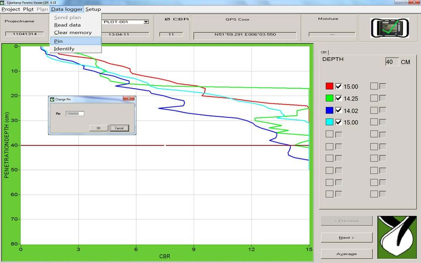
10. Problems and their removal............................................................................................................................................... 33
    10.1 Communication between thePC and the penetrologger............................................................................... 33
    10.2 Operating the penetrologger.................................................................................................................................. 33
    10.3 Creating a measurement plan................................................................................................................................34
    10.4 Carrying out the measurements............................................................................................................................34
    10.5 The Penetroviewer CBR............................................................................................................................................35
    10.6 Resetting the penetrologger...................................................................................................................................35

11. Power supply GPS, LCD and servicing .............................................................................................................................35
    11.1 Power supply...............................................................................................................................................................35
    11.2 GPS Receiver................................................................................................................................................................36
    11.3 LCD screen with background lighting..................................................................................................................36
    11.4 Service...........................................................................................................................................................................36

Literature ................................................................................................................................................................................... 37
Appendix 1 penetrologger menus.........................................................................................................................................38
Declaration of Conformity......................................................................................................................................................... 41

Nothing in this publication may be reproduced and/or made public by means of print, photocopy, microfilm or any other means without
previous written permission from Royal Eijkelkamp. Technical data can be amended without prior notification.
Royal Eijkelkamp is not responsible for (personal) damage due to (improper) use of the product.
Royal Eijkelkamp is interested in your reactions and remarks about its products and operating instructions.

                                                                                          3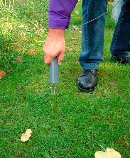
About these operating instructions
Symbols (as shown left) are meant for technical requirements of which the user must take special note.
Caution (symbol shown at left) is meant for work and operation processes that must be strictly
adhered to in order to prevent danger to persons. The user is responsible at all times for complete
personal protective equipment.
Refers also to working and operation processes that must be strictly adhered to in order to prevent
damage to or destruction of the penetrologger.
Text Text between inverted commas “….” (or italics) means that the text is exactly as shown on the screen.
Introduction
The CBR-penetrologger is a device specially designed for measuring the CBR value (= Californian Bearing Ratio)
of the soil; at the same time this instrument automatically saves the measuring results obtained and thus
makes possible their further processing on a PC.
The penetrologger is distinguished by an ergonomic design, its low weight and its user-friendliness. It permits
measurements up to a depth of 70 cm. The penetrologger displays the CBR value for each measurement.
The penetrologger contains a GPS system for exact determination of the measurement position. The coordinates
displayed by the penetrologger can be allocated with the aid of certain software (or somewhat less accurately
over the Internet) to a site or a map.
Optionally a soil moisture sensor (Art.-No.: 061550) can be connected to it in order to determine and save the
soil moisture percentage (single-point measurement) of the measuring position.
The penetrologger permits the direct storage and processing of 1500 measuring data (CBR data including GPS
and soil moisture data). For this reason this instrument is suitable above all for comprehensive test series.
The penetrologger possesses a built-in arrangement for displaying the penetration speed, as a too-quick or
impact method of advance will result in values that are not representative of the measured soil. This method
is precise and possesses a measuring range of von 668 N (15% CBR).
1. CBR (Californian Bearing Ratio)
The Californian Bearing Ratio investigation (short CBR) is a method of testing with the help of which the
carrying capacity of soils and hydraulically bound layers (rather seldom) can be investigated. The procedure
was originally developed for compaction of airport surfaces and is meanwhile also used in road construction.
It was developed by the “Californian Department of Transportation“. Basically the investigation displays the
force needed by a plunger pressed into a sample of soil in order to achieve a defined penetration speed up to
a defined depth. The better the carrying capacity of the soil sample, the higher the generated plunger pressure.
A soil CBR value is an index of the shear resistance under standard loading as compared to the shear resistance
of a standard material (crushed limestone) under the same loading.
The CBR investigation is described in the MIL CRD-C 654-95, ASTM Standards D1883-05 (for samples prepared
in the laboratory) and D4429 (for field soils) and AASHTO T193.
It is necessary to carry out measurements in depths, taking into account deviations, of the soil capacity for air
traffic with and without prepared start and landing strips.
The measuring results of the penetrologger are validated in order to characterize the CBR values of the soil
as described in the TTRL Report 901.
4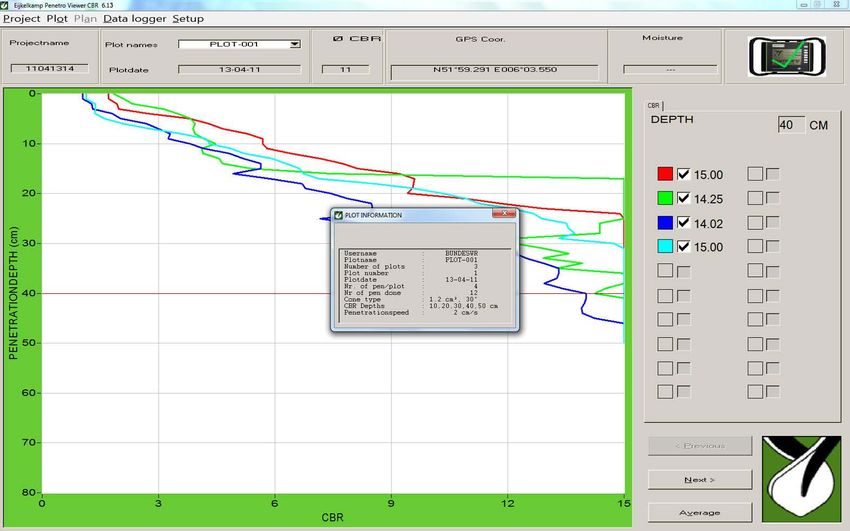
1.1 Average CBR value; calculation per penetration
The penetration depth (70 cm) is divided into 5 customer-specific,
adjustable depths. The CBR value (1 to 5) is measured at these depths.
CBR 1 (first value) and CBR 5 (last / deepest measurement) are the
determining CBR values and saved as individual values per cm. Values
2, 3 and 4 are supplementary information.
1.2 Influence of the soil moisture content and the
content of the organic contents
The penetration resistance of the soil depends, among others, on the
soil moisture content. The higher the degree of moisture of the soil,
the lower its penetration resistance and the lower its carrying capacity.
In the comparison of penetration resistances that are measured at
different points in time (for instance before and after a particular soil
processing), one must ensure that the soil moisture conditions during Measuring soil moisture
the measurement are comparable. In practice, comparable moisture
values are best ensured in that the penetration resistance is determined at field capacity (pF-2). The soil
moisture content of the measuring point can be defined and saved with the aid of the optional soil moisture
sensor (Art.-No.: 061550).
1.3 Influence of the spatial variability
In the determination of the penetration resistance the spatial variability of the soil must also be taken
into account. The differences with regard to texture, the structure or content of organic content can differ
substantially on a parcel level. As all these factors determine the penetration resistance, it is first necessary
to make repeat measurements in order to receive a representative value. The number of necessary repeat
measurements is oriented to the desired precision and the natural variability of the soil. The literature (for
instance Campbell & O’Sullivan, 1991) recommends 10 measurements per plot because of the soil formation
due to the impression of the cone. The spacing between the individual measuring points is at least 50 to 60
cm. The Netherlands standard for electrical penetrations (NEN 5140, 1996) promotes a spacing of at least 100
cm between penetrations.
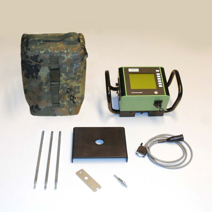
2. Description
The CBR penetrologger is normally supplied as a complete set for measurements to a depth of up to 70 cm.
Such a set is comprised of the penetrologger itself, suitable CBR cones, conecheck key, probe rods, a depth
reference plate, cable, software and a test protocol. Accessories such as soil moisture sensor (061550) are
obtainable as option. All these parts are packed into a carrying bag.
The complete penetrologger (see picture) consists of a housing (a) with GPS antenna (7), a LCD display (8), a
key pad (9), a level (10), and a force absorber (2). The logger has a spray-water protected housing with hand
grips (11). The penetrologger is provided with power by means of batteries.
The cone-shaped point or “Cone” (4) is screwed on below the three-part probe rod (3).
When the cone is forced into the soil, the penetrologger registers the depth up to 70 cm with great precision
by means of an internal ultrasound sensor whereby the depth reference plate (5) comes into use.
The measured penetration resistance, the GPS data and – if the optional soil moisture sensor is connected
to the communication port (6) – the percentage of soil moisture are saved into the internal Logger of the
penetrologger.
The average value of the CBR values and the standard deviation can be calculated automatically. If the cable
(13) is connected to the communication connection port (6) and to the PC, then data can be exchanged between
the Logger and the PC. The accompanying software permits the reading out of the data to the PC, the graphic
and numerical representation and the printing out of the data.
The conecheck key (12) is used for checking the wear on the cones. The cone must be replaced when it fits
through the hole.
5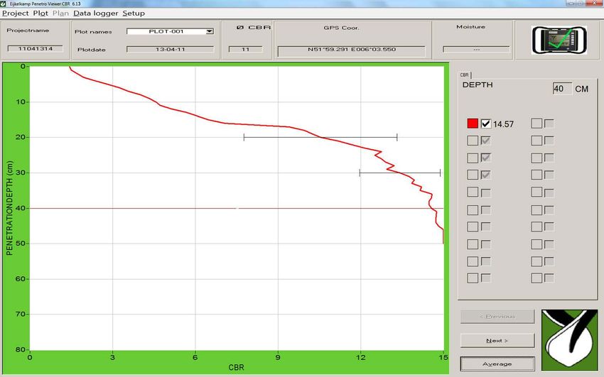
3. Technical specifications 7 8
10
Environment
Temperature -10 to +70 °C 9
Moisture 0..100%RH
Temperature shock 50 °C 11
1
Physical
Dimensions of bag 30x25x15 cm (h x w x d)
Total weight 5.5 kg 2
IP classification IP 54 (spray water / watertight)
The cone is CBR standard with adherence to NATO specification.
Diameter 0.5 inch (1.27 cm) /upper edge of cone
Top angle 30 ° 3
Surface 0.2 Inch2 (1.27 cm2) cone
Penetration depth 0-70 cm
Penetration resolution 1 cm
Penetration speed 1-5 cm/sec
4
Penetration force 0 - 700 N (0 - 15% CBR)
Penetration resolution 0.1% CBR Penetrologger
Penetration accuracy 2% (re-calibration with error >5%)
GPS accuracy 2 m CEP Circular Error Probable
3.5 m SEP Spherical Error Probable
(Egnos compensated)
CEP, 50% 24-hour static, - 130 dBm
(type µBlox LEA-6H)
Display LCD monochrome green/black
Background lighting LED intensity + contrast adjustable 6
Power supply Battery pack Lithium SEM52 8.4 V or BH8AA 12 V
Battery life > 600 measurements
Memory 1500 penetration measurements 5 13
12
Levelling Spirit level (bubble level)
Moisture Optional sensor available Penetrologger set
Measuring mode
Calculating the average value: Ø CBR = (measuring values CBR depth 1 (X) to measuring values CBR depth 4 (Y))
/ n (= No. of measuring values between X and Y = per centimetre of a measurement).
Ø CBR average value is rounded down (e.g. CBR 7.9 CBR 7)
Range for calculations: Ø CBR average value can be entered for 2 (CBR depth 1 (X) and CBR depth 4 (Y)) users.
6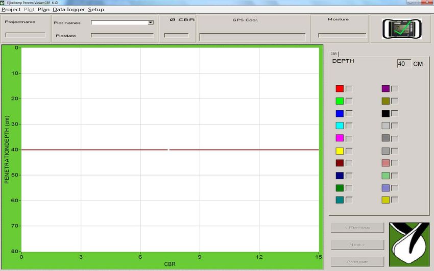
4.       The procedure
Before starting the measurements with the penetrologger, a plan for the field measurements must first be
established (Chapter 5. Plan for field measurements). Such a measurement plan contains the definition of the
field measurement positions, the number of measurements that will take place at the individual measuring
points, and the settings of the penetrologger (for instance the speed of penetration).

If desired, the desired measuring plan can be created on the PC or on the penetrologger itself (Chapter 7.
Creating a plan with the aid of the penetrologger). Practically, it is more convenient to make use of a PC (Chapter
6. Creating a plan on the PC). To this purpose the Penetroviewer CBR software needs to be installed on the
computer. If the PC is now connected to the penetrologger via the communication cable, then the created
measuring plan is transferred from the PC to the penetrologger.

After creating the plan, the penetrologger is ready for use and thus permits the measurement of the penetration
resistance. Now the prescribed measurement are carried out at each measuring point in the field (Chapter
8. Carrying out the measurements). The corresponding results are automatically saved in the logger where
there is an upper limit of 1500 measurement results. It is also possible to adapt the measurement plan in the
penetrologger on site (Paragraph 7.4).

The measuring results can be called up on site on the penetrologger in graphic or in numerical depiction
(Chapter 9. Processing the measuring data). The software also permits the reading out of the data on the PC,
the processing of these data, transfer to other programs, and printing out on a printer.

                                                     7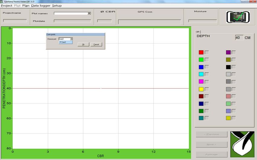
5. Planning the measuring for field measurements
5.1 Creating a plan
PLAN X
This type of plan consists of a hierarchical structure
of projects, plots and penetrations (see picture). Project 1
A project consists of several plots (measuring
positions). A penetration resistance is determined at Plotname 1
each individual plot. In this, one or more penetrations Penetration 1
(measurements) are carried out per plot in order to Penetration 2
arrive at a representative average value for the plot. Penetration 3
Penetration 4
The following general parameters are created for
each project: Plotname 2
Project designation Penetration 1
User name (e.g. BW) Penetration 2
Plot designation Penetration 3
Penetration speed Penetration 4
Number of plots
Quantity of soundings per plot (max. 20) Plotname 3
Penetration 1
Penetration 2
5.2 Example
Penetration 3
An example of one such measuring plan is
Penetration 4
“Plan X”:
Project 2
Plotname 1
Penetration 1
Plotname 2
Penetration 1
Project 1 (Strip 1) Project 2 (Strip 2)
PLOT 1 PLOT 1
PLOT 2 PLOT 2
PLOT 3
Example of a measuring plan
8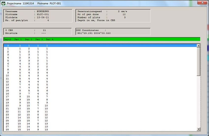
6. Creation of a plan on the PC
The creation of a plan on the PC and the later transfer to the penetrologger has the advantage that the entry via
the keyboard of the PC is often easier. This method saves much time, especially when special plot designations
are to be used, which can be time-consuming as regards the typing effort. One or more projects can be defined
per plan, in fact up to a maximum of 1500 penetrations.
Several plans can be saved on the PC and these can be called up later as required. However, the penetrologger
can only save one plan. This plan can contain several projects. In the case that several plans are used in the
field, then it is advisable to use a Laptop.
6.1 Installation of the software
System requirements:
Windows 7, 8 or 10
1. First insert the “Penetroviewer CBR” DVD into the drive. The Auto-Run program starts, follow the instructions
of the screen. If the Auto-Run program does not start, then the Setup file can be started manually.
Select “Setup” and click on “Open”. To confirm, click on the command button “OK”.
When downloaded: Install the Penetroviewer software. Click on the Setup. exe file and the installation starts,
follow the instructions on the display.
2. In order to select a different folder for the Penetroviewer, click on “Change” and enter the desired folder.
The standard target folder is “C:\Program Files\PenViewer”.
To confirm, click on the “OK” command button.
3. Click on “Next” in order to start the installation or “Abort” to stop the installation process.
4. The PC must be restarted to activate the changes. Click “YES” to start automatically or “NO” if it is intended
to start later.
Penetroviewer main window
9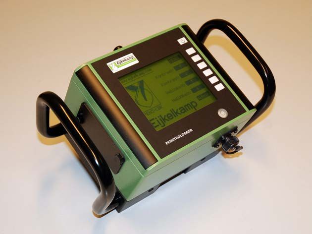
6.2 Starting and ending the Penetroviewer
1. To start the Penetroviewer, click the Eijkelkamp Penetroviewer shortcut in the Windows Start menu under
Programs, Eijkelkamp Penetroviewer, Penviewer.
Then a window with the Eijkelkamp logo appears and disappears again a few seconds later to be replaced
by the main window of the Penetroviewer (see picture).
2. When used for the first time, the main window has an English language menu bar. If the German language
is desired, select “Language” under “Tools” in the menu bar and place an X in the “German” box.
3. To close the Penetroviewer, click “Close” in the menu bar under “Project” or click the X at the top right of
the window.
6.3 Set-up
The following parameters are shown in the Set-up
Export
Language
Comm.Port
Info
When used for the first time, the main window has an English language menu bar. If instead the German
language is desired, select “Language” under “Tools” in the menu bar and place and tick in the “German” box.
The software automatically finds the available communication ports on the Computer. The correct communication
ports must be selected when the penetrologger is first connected.
Connect the penetrologger to the computer and switch it on. Go to Tools Comm. Port and select one of the
available communication ports.
When you have selected the correct port a green tick (‘’) appears in the small depiction of the penetrologger
(top right in the picture). If the incorrect port is selected, a red X will appear instead and another port must
be selected.
Setting up the communication port
10Either a long or a short version can be selected as export format. The long version is suitable for further
processing in Excel. For this, select Export TXT file pro cm depth under Set-up / Export in the menu bar (for
further information see 9.2.4).
The short version is suitable for the “Go-book”. For this, select Export TXT Average value under Set-up/Export
in the menu bar (for further information see 9.2.4).
6.4 Standard parameters
Certain standard parameters are set before the creation of a measuring plan. The corresponding values are
filled in automatically in a time-saving method when creating a plan
The following standard parameters are filled in for “Standard” under “Plan” in the menu bar:
Company Enter a maximum 8-character company name – withoutspacing. A difference is made here
between upper and lower case letters. Normally the name appears between square brackets
In the first use, this is: [COMPANY].
Number of plots Here the desired number of plots that will be used within the scope of a given project is
entered with a max of 1500. Normally this number appears in square brackets. In the first
use, this is: [1].
Pen. per Plot Select the desired number of penetrations that are to be carried out per plot. Normally the
number of penetrations per plot is: [1] (max. 20)
Pen. speed Select the desired penetration speed (cm/sec) for the measurements. The recommended
value is 2 cm/sec (see Paragraph 7.2).Normally the penetration speed is set to: [2].
CBR depth Normally all values between 0 cm and 60 cm are used for average calculations of the CBRs
per penetration. It is possible for the project to pre-select other areas (e.g. measurements
between 10 cm and 50 cm).
Type of cone The CBR cone type is pre-selected.
6.5 Creating a measurement plan
6.5.1 Entering a measurement plan
1. A plan is created by selecting “New Plan” in “Plan” in the menu bar.
This opens the “Add Project” window.
If a new plan is to be created, then no other plan must have already
been loaded in the Penetroviewer. Therefore first close the already
loaded plan (see Paragraph 6.5.2).
2. In the next step, click New Project in order to define a new project within
the plan.
This opens the “EDIT PROJECT” window.
Add project window
11Edit Project window
3. Now the following entries can be changed
Project name Normally based on the date (Year-Month-Day) and the sequential number; enter a
unique designation, maximum 8-character entry.
Company Maximum 8-character entry.
Type of cone CBR cone (cannot be changed)
CBR depth CBR-1 (X) starting depth average calculation Ø CBR
CBR-4 (Y) End depth average calculation Ø CBR
CBR-5 (End depth penetration)
Penetr. speed 1, 2, 3, 4 or 5 cm/s.
No. of plots 1 ... 1500
No. of penetrations per plot 1 ... 20
Plot name Normally all plots within a given project possess a unique name, i.e. they are named
on the basis of a sequential number. These numbers have a maximum length of
8 characters.
The same penetration speed should always be used with several measurements in order to ensure
that the results are reproducible.
4. The project is defined by a mouse click on “OK” when everything is entered as desired (also the whole
project can be removed with Back).
5. Repeat steps 2-4 until all the desired projects have been entered.
In this connection, it should be pointed out that a total of maximum 1500 penetrations can be reserved in the
penetrologger. If this limit is reached during creation (the Penetroviewer calculates this automatically), then
the New Project button no longer appears in the “SELECT PROJECT” window. Also, in this case no additional
plots and penetrations can be defined anymore.
6. Save the completed plan (see Paragraph 6.5.2).
126.5.2 Saving and ending the measuring plan
As soon as the changes of the settings have been carried out, a window appears (irrespective how)
with the query whether the changes should be saved or not (Yes/No/Abort). The saved plan can then
later be used again or can be processed (see Paragraph 6.5.3)
1. Now select the “Save” option in “Plan” in the menu bar and enter a name for the plan. Then select the
desired folder in which the plan file is to be saved. The file will have the suffix ”pla”.
If the file name already exists, then the operating guide in the dialogue window asks whether the existing
file is to be overwritten. If the file is to be overwritten, confirm by means of a mouse click on Yes; otherwise,
click No and enter a new name.
2. If (after successful saving) the plan is to be closed, select Close in “Plan” in the menu bar.
Then a dialogue window appears with the query whether you really want to close the plan. With Yes the
plan is closed and No annuls the command (this does NOT delete the plan from the hard disk!).
After successfully closing the plan, the Penetroviewer can be used to create a new plan or to load an existing
plan.
6.5.3 Opening and processing a measuring plan
1. If an already existing plan is to be opened, select “Open” in “Plan” in the menu bar.
However, the Penetroviewer can only save one plan at a time. For this reason, if a processed plan is already
open, a dialogue window will appear with the request to save the current plan.
2. Now open the desired folder in which the file with the “pla” suffix is located and select the file. The file is
loaded with Select and the process is aborted with Abort.
3. If the loaded plan is to be processed, select “Edit Plan” in “Plan” in the menu bar. After successful selection
of a plan, the settings can be adapted using Edit project.
6.6 Transferring a measuring plan to the penetrologger
The plan created on the PC can now be transferred to the penetrologger. For this purpose, the penetrologger
must first be connected to the PC.
1. Remove the protective cap on the communication connection of the penetrologger. Then connect the
communication cable to the communication connection. The connection only fits if properly installed. Insert
the plug firmly and fasten the connection by screwing up the rotating ring.
2. Connect the other end of the communication cable to a serial communication connection of the PC.
3. Place an X next to the correct communication connection for the Penetroviewer at Comm. Port under “Tools”
in the menu bar.
4. Now the penetrologger can be switched on by pressing the top white button. If there are no batteries in
the penetrologger, these must now be inserted (see 11.1 “Power supply”).
The PC will now automatically recognise the penetrologger and activate the Datalogger menu in the menu
bar.
5. In the next step, select Identify under Datalogger in the menu bar.
Then the penetrologger is recognised by the PC. The display of the penetrologger then shows the text
“COMMUNICATION WITH YOUR PC WAS SUCCESSFULLY ESTABLISHED!”.
13The Penetroviewer possesses a “LOGGER INFORMATION”
window with the serial number of the hardware and software
versions.
Close this window to continue.
6. Use Send plan in Datalogger in the menu bar to transfer the
plan to the penetrologger.
In a window, the operator guidance asks whether the plan
is really to be transferred to the penetrologger. Transfer the
plan with Yes; abort the procedure with No. Logger Information window
When transferring a plan to the penetrologger, all existing data in the penetrologger (the plan
including the possibly existing measuring data) are deleted. This is because the penetrologger can
only save one plan at a time. Before this, a warning will appear on the screen.
The penetrologger is now ready for operation and can carry out measurements. If desired, the plan in the
penetrologger can still be adapted (see 7: “Creating a plan with the aid of the penetrologger”).
7. Finally remove the communication cable and screw the protective cap back on again.
7. Creating a plan with the aid of the penetrologger
The direct creation of a plan in the penetrologger has the advantage that the measuring plan can be created or
processed in the field. This is of help, above all if one does not know exactly in advance how many and which
plots are to be measured or which cone is to be used. As the default parameters can be used in the creating,
the creation on site need not necessarily be time consuming.
The creation or processing of a measuring plan can only be carried out by means of Admin or PC
software!
7.1 Operating the penetrologger
The penetrologger has 7 function buttons. The functions of
the individual buttons can be seen in the display; in this 1
2
the text appears in a dark block besides the respective
keys. All menu functions are described in Appendix 2. 3-7
Key Function
1 Switch-on button
2 Menu selection
3-7 Dependent on the selected menu
1. Press Key 1 to switch on the penetrologger. The start
menu appears.
Communication
Operation of the penetrologger
142. If desired, set the contrast and brightness of the LCD display with the arrow buttons.
A brighter screen adversely affects the battery life.
www.eijkelkamp.com MENU
Contrast + ↑
Contrast - ↓
Brightness + ↑
PEN6/CBR Brightness - ↓
ADMIN
Eijkelkamp
Setting contrast and brightness screen
3. Open the main menu with “MENU” (after the plan has been created either by means of Admin or PC software!)
PLAN
MEASR
VIEW
PEN6/CBR
EDIT
INFO
QUIT
7 SELECT ITEM...
Main menu screen
* PLAN and EDIT, only visible as ADMIN
MEASR, only visible when a plan has been created.
VIEW, only visible after a measurement.
4. If a different language is desired, you can switch into your preferred language.
1. For this, activate EDIT in the menu bar (depending on the current language).
2. With the aid of the arrows, go to SPRACHE [DEUTSCH], German, IDIOMA Español, LANGUE Français or
LANGUAGE [ENGLISH] and confirm your choice with OK.
3. In the next step, select ENGLISH depending on the chosen language. After a short period of time, the
English language is activated.
157.2 Standard parameters and settings
Certain parameters are prescribed before creating a measuring plan. The corresponding values are then
automatically applied during the creation of a plan and this saves a lot of time. In addition, certain settings
of the penetrologger can be defined.
1. Activate the “EDIT” key in the main menu. The “EDIT SYSTEM MENU” appears.
EDIT SYSTEM MENU MENU
COMPANY BUNDESWR
DEPTHS CBR 10 / 40 CM
PEN. SPEED 2 ↑
NR. OF PLOTS: 4
PENETR./PLOT: 3 ↓
SHUT OF TIME : 38
GPS: On
MOISTURE: Off
LANGUAGE: ENGLISH
DATE 13-04-11
TIME 11.48.21
CALIBRATION
OK
CLEAR MEMORY
Edit system menu screen
2. In the “EDIT SYSTEM MENU“, enter the standard parameters and the setting data of the penetrologger. Here
it is pointed out that the standard values are set without reference to the Penetroviewer. Thus, it is possible
that there are different standard values on the PC and the penetrologger!
However, the individual objects can be reworked in that the selected entry is chosen using the arrow buttons
and confirmed with “OK“. In the next step, use the horizontal arrows to go to the desired position and change
the sign using the vertical arrows. The changes are confirmed with “OK“ and the processing is ended; with
“MENU” the display returns to the previous menu. The following is an overview of the “EDIT SYSTEM MENU”.
Standard parameters
COMPANY [BUNDESWR] User name
DEPTHS CBR CBR-1 (X) starting depth average calculation Ø CBR
CBR 2 and 3 inactive
CBR-4 (Y) End depth average calculation Ø CBR
CBR-5 (End depth penetration)
PEN. SPEED [2] Penetration speed in cm/s The recommended constant speed is 2 cm/s with
a maximum deviation of 0.5 cm/s (according to NEN 5140, 1996)
NR. OF PLOTS [1] No. of plots for the project (1 … 1500).
PENETR./PLOT [1] No. of penetrations per plot (1… 20).
SHUT-OFF TIME [10] Time in minutes after which the penetrologger shuts itself off. Choice poss.
1… 60 Min. Five beeps are heard immediately prior to the automatic shut-off
function.
GPS [On] Switching the GPS function On and Off
MOISTURE [Off] Switching the optional soil moisture sensor On and Off.
LANGUAGE [English] Languages: Dutch, German, French, Spanish or English
DATE [13-04-11] Current date
TIME [11:48:21] Current time
CALIBRATION The user cannot calibrate the penetrologger himself!
16 The user cannot calibrate the penetrologger himself. The calibration occurs in the factory and usually
does not need to be adapted by the user.
Eijkelkamp Soil & Water recommends an annual works calibration control.
CLEAR MEMORY Deleting the penetrologger memory. After selection a box will appear with the question
“DO YOU REALLY WANT TO DELETE THE MEMORY?” Confirm this with “YES” and depress
this button for 5 seconds (whereby five beeps can be heard) in order to delete the
memory of the penetrologger. The procedure can be aborted with NO and the display
returns to the “EDIT SYSTEM MENU“.
The memory should only be deleted when it is certain that the current data (the plan and the possible
measuring data) in the penetrologger will no longer be used. The existing data are completely deleted!
7.3 Creating a measurement plan
1. In the penetrologger only 1 plan can be created and saved at any one time. Therefore, before creating a new
plan a possibly existing plan must be removed from the penetrologger (if desired, first save the existing
plan on a PC). The procedure is as follows:
Delete the memory of the penetrologger (see Paragraph 7.2), or
Create the plan on the PC and transfer this to the penetrologger, whereby the memory of the
penetrologger will first be automatically deleted.
2. In the next step, select “PLAN” in the main menu. This brings up the “PLAN MENU”.
3. Now select a project and a plot with PROJ, PROJ, PLOT or PLOT.
Except for an already defined project, there now exists a new undefined project that can be recognised by the
text “NEW PROJECT” at the bottom of the display. The corresponding project designation consists of a unique
number that contains the following information: Year number – Month – Time - sequential number. A new
project is created on the basis of this undefined “Empty project”.
PLAN MENU
MENU
SELECT PROJECT
PROJECT: 11041316 ↑ PROJ
COMPANY: BUNDESWR
PLOT: PLOT-001 ↓ PROJ
CONE CBR: 1.2 cm2 30°
PEN. SPEED: 2
NR. OF PLOTS: 4 ↑ PLOT
PENETR./PLOT: 3
DEPTHS CBR: 10 - 20 - 30 ↓ PLOT
40 - 50 cm
NEW PROJECT
OK
Plan menu select project screen
17The desired project is created with “OK”. The “EDIT PROJECT” sub-menu now appears.
PLAN MENU
MENU
EDIT PROJECT
PROJECT: 11041316 ↑
COMPANY: BUNDESWR
PLOT: PLOT-001 ↓
CONE CBR: 1.2 cm2 30°
PEN. SPEED: 2
NR. OF PLOTS: 4 SAVE
PENETR./PLOT: 3
DEPTHS CBR: 10 - 20 - 30 EDIT
40 - 50 cm
NEW PROJECT
Plan menu Edit project screen
4. To edit the project, process the entries with “EDIT“. There now appears the sub-menu with which various
items can be adapted.
PLAN MENU MENU
←
PROJECT: 11041316 →
↑
↓
OK
Plan menu Edit screen
The entries in the sub-menu can be changed with the aid of the arrow buttons. The changes are saved with
“OK” or are aborted with ”MENU“ whereby the display returns to the “SELECT ITEM“ menu.
At this point it is pointed out that only the plot designations of the plot selected under point 3 can be
changed.
185. The created project is defined with “SAVE”.
Now the text “PROJECT DEFINED” appears at the bottom of the display.
The project is definitely saved with the definition. After this, neither the number of plots nor the
number of penetrations per plot can be changed!
6. With “OK” or “MENU” the display returns to the “SELECT PROJECT” menu. If desired, the remainder of the
plot designations of the defined project can be changed with the working steps 3 and 4.
7. If desired, more projects can be created with the process steps 3-5.
8. Return to the main menu with “MENU“ and end the plan data entry.
7.4 Processing a measuring plan
Once a project has started, the number plots and the number of penetrations per plot can no longer
be changed. It is also not possible to remove an individual project from the plan.
1. Switch on the penetrologger and open the main menu.
2. Now run through the steps 3 and 4 of Paragraph 7.3.
If measurements within the scope of a project have already taken place, then the project can no longer be
changed. However, the affected project can still be selected with “PLAN MENU” but in this case the OK button
is not active. The text “PROJECT ACTIVATED” appears at the bottom of the display and “PLOT ACTIVATED” appears
under the relevant plot.
3. Return to the main menu with “MENU”.
Information
in the case that a project is unusable due to an entry error or a changed situation, then two possibilities
present themselves:
Definition of a new project, whereby the unusable project remains in the plan. However, here it must be
ensured that only valid projects are selected for the measurements.
Deletion of the whole plan in that the memory of the penetrologger is deleted and a new plan is created.
But here one must not forget that all the data saved in the memory of the penetrologger (the plan as well
as all the measuring data) will be deleted! Details on deleting the Logger memory can be found in Paragraph
7.2.
8. Carrying out the measurements
Before the measurement, certain aspects should be checked in the “SYSTEM INFO MENU“ (select “INFO” in the
main menu for this):
GPS satellite information
The current date and time
The battery. The type of battery and the remaining capacity of the battery in % (is shown based on the
battery voltage). A value of 100% corresponds to a full battery.
Service counter: Overall counter.
The serial number of the penetrologger
The software version.
The hardware version.
The number of carried out measurements (penetrations) in the memory.
The number of remaining measurements (“Reserved”).
19Background lighting and contrast settings menu is selected with the accompanying button.
Switch loudspeaker On or Off with the relevant button.
1. Install the associated (three-part) probe rod and screw the cone on tightly. Use suitable tools for tightening.
Then screw the probe rod with the coupling into the penetrologger and tighten the screw.
The fastening should be carried out by light hand-tightening (in order to avoid damaging the force
sensor).
The cone wears out with use. For this reason, its dimensions must be checked before use with the Conecheck
key. If the cone can be pushed through the Conecheck key (see 2 “Description”), then the cone is unsuitable
for reliable measurements. Also asymmetrically worn sounding points are impermissible.
3. Optional: Connect the soil moisture sensor to the communication port of the penetrologger.
The instrument is ready for use after completed data entry (Plan/project/plot) and installation of the
penetrologger.
4. Switch on the penetrologger.
The GPS determination takes longer when the penetrologger is used in a particular area for the first time.
The time for subsequent measurements is shorter (< 8 seconds),
5. Select “MEASR” in the main menu.
This brings up the “MEASUREMENT MENU“in which the desired project is selected. Also the project settings
entered appear here.
MEASUREMENT MENU
MENU
SELECT PROJECT
PROJECT: 11041316 ↑ PROJ
COMPANY: BUNDESWR
PLOT: PLOT-001 ↓ PROJ
CONE CBR: 1.2 cm2 30°
PEN. SPEED: 2
NR. OF PLOTS: 4
PENETR./PLOT: 3
DEPTHS CBR: 10 - 20 - 30
40 - 50 cm
PROJECT DEFINED
OK
Measurement menu window
Now select the desired project and confirm your choice with “OK“.
20This brings up the measurement screen. Now the first plot of the selected project can be measured.
MEASUREMENT MENU
MENU
L PROJECT: 11041316 X-V CM
PLOT: PLOT--001 Ø CBR
PENETR.: 1 ---
START
0
D
E 10
P
20
T
H 30 Act
C
40 0
M 50
Depth
S 60
70 70
0 0 3 6 9 12 CBR (0-15)
Measurement screen
The plots can only be measured in the sequence of their definition.
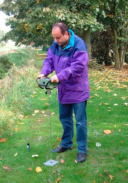
6. Place the depth reference plate horizontally on the ground with
the two turned-up edges facing downwards. Push the cone of the
penetrologger through the opening of the depth reference plate into
the ground. For the following reasons, attention must be paid to an
optimal vertical direction:
Distribute the force as evenly as possible over both grips (too-great
force differences can damage the force sensor).
The vertical direction is checked by the level gauge of the
penetrologger. In this the slant angle of the penetrologger must not
deviate by more than 3.5° from the vertical. This is to prevent that
the friction between the rod and the soil influences the penetration
resistance value.
In order to ensure correct depth measurement, an ultrasound sensor
serves for measuring the penetration depth. The ultrasound signals
sent by this sensor are reflected at the depth reference plate and
return from it to the sensor.
In order to obtain reliable measurements from the ultrasonic
sensor, it is recommended in strong wind to place oneself
with the back to the wind (certain wind noises can disturb the Measuring with the penetrologger
ultrasonic measurements).
7. Select “START” to begin the measurement.
If “Moisture” is on “Yes” (see Paragraph 7.2) then the penetrologger displays:
Set Thetaprobe and press Start. Then the soil moisture percentage is shown first: SAVE Thetaprobe…% VOL. ?
If this is OK, select YES (percentage is saved).
With a renewed press on START, a start can be made with the penetration resistance measurement.
218. After pressing “START” the penetrologger wants to null the force sensor.
In the nulling proces you may be asked to relief the force (“RELIEF FORCE !!“)of the sensor by lifting the
instrument and confirm with the “OK” key.
MEASUREMENT MENU
PROJECT: 11041316 X-V CM
PLOT: PLOT--001 Ø CBR
PENETR.: 1 ---
RELIEF FORCE !!
OK
0
Measurement screen
If the nulling proces is not within specifications you can continue but the message “UNCALIBRATED“ will
appear and the file name will be changed for the first four characters by “!!!!” (i.e. filename 11041316 will
change in !!!!1316).
MEASUREMENT MENU
PROJECT: !!!!1316 X-V CM
PLOT: PLOT--001 Ø CBR
PENETR.: 1 ---
UNCALIBRATED !!
OK
0
Measurement screen
Confirm with the “OK” key.
229. Now press the penetrologger evenly and as vertically as possible with constant
speed into the soil according to the measuring plan. At the recommended speed
of 2 cm/s, the prescribed depth of 70 cm is reached in about 40 seconds.
In the display there appears the deviation from the prescribed speed (± 40
percent) in form of a speed indicator. If the penetration depth falls above or below
the permissible range (whereby the Logger will emit a beep at 30 percent), the
measurements are aborted as in this case no representative result can be obtained.
If the speed display shows a deflection downwards (to “S”), then the advance is too
fast. In this case, one should press slower into the soil.
If, in contrast, there is a deflection upwards (to “L”), then the advance is too slow.
In this case, one presses the instrument quicker.
With a penetration speed that is too fast, a warning appears on the screen “MEASUREMENT
INVALID”. Select “STOP” to end the measurement; the data are not saved.
With a penetration speed that is too slow, a warning also appears on the screen
“MEASUREMENT INVALID”. However, here it is possible to save the data.
The penetrologger is
pushed into the soil
MEASUREMENT MENU
1
MENU
L PROJECT: 11041316 X-V CM
PLOT: PLOT--001 Ø CBR
PENETR.: 1 ---
START 4
8
0
D STOP
3 E 10
P
20
T
H 30 Act
2
C
40 0 5
M 50
Depth
S 60
70 70 6
7
0 0 3 6 9 12 CBR (0-15)
Measurement screen
Various parameters can be read off in the “MEAS MENU” window.
1. Short project description (PROJECT)
2. Graphic representation of depth and associated CBR.
3. Penetration speed
4. Average value CBR (Ø CBR)
5. Current CBR (ACT)
6. Penetration depth in cm (DEPTH)
7. Status of GPS connection
8. GPS coordinates
23The average Ø CBR is an indicative value that is rounded down. It is always rounded down to whole numbers.
The current and graphic CBR values are un-rounded measuring values.
If the sensor during the measuring is not in a position to receive the ultrasonic signals and no correct depth
measurement can be measured, then the sign “- - -“ appears in place of the actual depth display. In this
case the measurement should be aborted.
10. When the end depth of, for instance, 70 cm is reached, then the measurement is ended. The measurement
can be aborted early with “STOP” if one cannot reach the maximum depth or does not want to.
Answer the question as to whether the measurement is to be saved with “YES” (measurement, GPS
coordinates, possibly soil moisture percentage are saved) or “NO” in order not to use the measurement or
to repeat it.
In the case that the depth belonging to CBR 1 is not reached, then the message “MEASUREMENT INVALID”
appears. Select Canc. to end the measurement, the data are not saved.
MEASUREMENT MENU
MENU
L PROJECT: 11041316 X-V CM
PLOT: PLOT--001 Ø CBR
PENETR.: 1 ---
START
0
D CANC.
E 10
P
20
T
Act
H 30 MEASUREMENT
C
40 INVALID 0
M 50
Depth
S 60
70 70
5 0 3 6 9 12 CBR (0-15)
Measurement screen measurement invalid
11. If desired (depending on the prescribed number of penetrations per plot) a further repeat measurement at the
same plot can be carried out. For this purpose, choose a position at least 1 m away from the other measuring
position(s) so that the measurements do not influence one another. Also the remaining penetrations are
now carried out.
MEASUREMENT MENU
PROJECT: 11041316 X-V CM
PLOT: PLOT--001
PENETR.: 1
N51°59.335 E006°03.332
PLOT
READY
OK
5
Measurement screen plot ready
249. Processing the measuring data
9.1 Reading out on the PC
1. In order to read out the measuring results, connect
the penetrologger to the PC. See working steps 1-4 in
Paragraph 6.6
2. Now select “Read data” under “Datalogger” on the
menu bar.
All measuring results (only the actual measurements)
are transferred from the penetrologger to the PC.
3. After the reading out of the data on the PC. a separate
file with the suffix “*.pen” is created for each defined
project. A window appears for each individual project,
in which the file name is entered: here also select the
desired folder.
4. Finally, switch the penetrologger off, remove the
Processing data on the PC
communication cable, and screw the protective cap
of the communication connection tight.
9.2 Display on the PC
The file name is displayed on the title bar.
The measuring results can be displayed on the PC. In this, the measuring results – broken down according to
projects – can be shown selectively in graphic or numeric form. The project data are also suitable for processing
in spreadsheet format.
9.2.1 Opening and closing a project file
1. First select Open under Project in the menu bar. Then select the desired “pen” file (Project) in the folder in
question. The file is opened with Select.
The example file “Example.pen” is a standard file in the program folder of the Penetroviewer.
As soon as a file is opened, there will appear a graphic depiction of the plot results; now the Plot menu is also
available in the menu bar.
2. In order to close a given project file, select End under Project in the menu bar.
259.2.2 Graphic depiction
The following options are available in the graphic depiction of the results (see pictures):
All measurements are displayed
Graphic depiction of one measurement
All measurements (penetrations) for the plot in question appear here as standard. A particular measurement
can be faded out or selected again by means of a mouse click on a coloured box beside the graphic.
26 The results of the previous or the next plot can be called up with the aid of the “Previous” or “Next” buttons
at the right or under “Plot” in the menu bar.
The average value of all selected measurements of the plot in question can be called up by activating the
“Average value” button.
If only three of the ten measurements are selected (whereby the rest are faded out by mouse click on
the coloured boxes), then the average value of these three measurement results are given. This is used in
the case that disturbance values are to be eliminated. The average values of at least 2 measurements are
calculated and will also give the standard deviation at every 10 cm.
A repeated pressing on “Average value” brings all the individual lines up again.
If the depiction of the lines is to be changed, use “Line Type” under “Plot” in the menu bar. Here there is a
choice between “Line”, “Points” and “Bold line”.
The matrix in the graphic depiction can be faded in or out in that a cross is placed next to “Grating” under
“Plot” in the menu bar.
The horizontal measuring line in the graphic area can be shifted upwards or downwards with a mouse click
in that it is either pulled with the mouse or the desired position is clicked (alternatively one can make use
of the cursor keys on the keyboard).
The depth (in cm) belonging to the depth display is shown under “DEPTH” next to the graphic area. Under
“PRESSURE” the respective colour and the numerical value (MPa) for the depth mentioned in the measuring
line is shown for all measurements of the plot.
The corresponding measurement is shown under “CBR value” above the graphic display, the GPS coordinates
are shown under “GPS coordinates”, and the soil moisture percentage is shown under “Soil moisture”.
279.2.3 Numeric depiction
First select “Numeric” under “Plot” in the menu bar in order to call up a numeric overview of the currently
selected measurements (penetrations).
This brings up a measurement value for every centimetre of depth. If the average line is shown in the graphic
depiction, then the numeric data of the average value and the respective standard deviations are displayed.
In addition, all plot-referenced information appears.
Numeric depiction of all measurements
The minimum measuring value/penetration resistance determines the carrying capacity of the area.
Numeric depiction of the average value
28You can also read


