Phase-Separated Mo-Ni Alloy for Hydrogen Oxidation and Evolution Reactions with High Activity and Enhanced Stability
←
→
Page content transcription
If your browser does not render page correctly, please read the page content below
COMMUNICATION
                                                                                                                           www.advenergymat.de

Phase-Separated Mo–Ni Alloy for Hydrogen Oxidation and
Evolution Reactions with High Activity and Enhanced Stability
Jidong Song, Yan Qi Jin, Lei Zhang, Pengyu Dong, Jiawang Li, Fangyan Xie, Hao Zhang,
Jian Chen, Yanshuo Jin,* Hui Meng,* and Xueliang Sun*

                                                                                                   advantage of alkaline polymer electrolyte
The development of alkaline polymer electrolyte fuel cells and alkaline water                      fuel cells (APEFCs) and alkaline water
electrolysis requires nonprecious metal catalysts for the hydrogen oxidation                       electrolysis (AWE) is the use of nonpre-
reaction (HOR) and hydrogen evolution reaction (HER). Herein, it is reported                       cious metal catalysts, which is expected
                                                                                                   to significantly reduce the cost and pro-
a phase-separated Mo–Ni alloy (PS-MoNi) that is composed of Mo metal and
                                                                                                   mote the practical application of hydrogen
embedded Ni metal nanoparticles. The PS-MoNi shows excellent hydrogen                              energy.[6–8] At present, major obstacles to
electrode activity with a high exchange current density (−4.883 mA cm−2),                          the application of APEFC and AWE are
which is comparable to the reported highest value for non-noble catalysts.                         the slow kinetics of hydrogen electrode
Moreover, the amorphous phase-separated Mo–Ni alloy has better structural                          reactions and oxygen electrode reac-
and electrochemical stability than the intermetallic compound Mo–Ni alloy                          tions.[9,10] Hydrogen oxidation reaction
                                                                                                   (HOR) and hydrogen evolution reaction
(IC-MoNi). The breakdown potential of PS-MoNi is as high as 0.32 V, which
                                                                                                   (HER) belong to hydrogen electrode reac-
is much higher than that of reported IC-MoNi. The X-ray absorption near                            tions, and Mo–Ni alloy is one of the most
edge structure (XANES) and density functional theory (DFT) calculations                            promising electrocatalysts for hydrogen
indicate the electrons transfer from Mo to Ni for PS-MoNi, leading to suitable                     electrode reactions.[11–13] Intermetallic
adsorption free energies of H* (ΔGH*) on the surface of Mo. This means                             compound Mo–Ni alloy (IC-MoNi), such
                                                                                                   as MoNi4, MoNi3, and MoNi, will pro-
that the electron density modulation of Mo metal by embedded Ni metal
                                                                                                   duce a synergistic effect between Mo and
nanoparticles can produce excellent HOR and HER performance.                                       Ni for enhanced hydrogen electrode reac-
                                                                                                   tions.[14–17] However, since the Mo element
                                                                                                   in IC-MoNi is unstable during the elec-
Hydrogen energy economy is one of the important ways                         trode reaction process, the breakdown potential of IC-MoNi is
to improve the use of clean and renewable energy, and has                    low, resulting in poor electrochemical stability.[14–17] Moreover,
important economic and environmental significance.[1–5] The                  Ni also suffers from low stability at potentials about 0.1 V versus
                                                                             reversible hydrogen electrode (RHE) due to its relatively strong
                                                                             binding affinity toward oxygen species.[18] How to improve the
J. Song, Y. Q. Jin, P. Dong, J. Li, Prof. Y. Jin, Prof. H. Meng              stability of IC-MoNi has become an important challenge.
Guangdong Provincial Key Laboratory of Optical Fiber Sensing and
Communications                                                                  The phase-separated alloy is different from the intermetallic
Siyuan Laboratory                                                            compound alloy. For example, the phase-separated Mo–Ni alloy
Guangzhou Key Laboratory of Vacuum Coating Technologies and New              (PS-MoNi) is composed of phase-separated Mo metal phase
Energy Materials                                                             and phase-separated Ni metal phase. Because Mo metal phase
Guangdong Provincial Engineering Technology Research Center                  is stable and has a high breakdown potential,[17] the PS-MoNi
of Vacuum Coating Technologies and New Energy Materials
Department of Physics                                                        may have better structural and electrochemical stability than
Jinan University                                                             IC-MoNi. For PS-MoNi, the electron density of Mo metal can
Guangzhou, Guangdong 510632, P. R. China                                     also be adjusted by Ni metal, which is similar to IC-MoNi.[14–22]
E-mail: jinyanshuo@email.jnu.edu.cn; tmh@jnu.edu.cn                          In addition, amorphous materials are more resistant to corro-
Dr. L. Zhang, Prof. X. Sun                                                   sion due to the absence of grain boundaries. Therefore, amor-
Department of Mechanical and Materials Engineering
University of Western Ontario                                                phous PS-MoNi may be a good material for HOR and HER
London, Ontario N6A 5B9, Canada                                              with high activity and enhanced stability.
E-mail: xsun9@uwo.ca                                                            Herein, we synthesized the PS-MoNi composed of phase-
Prof. F. Xie, H. Zhang, Prof. J. Chen                                        separated Mo and Ni metal phases. The X-ray absorption spec-
Instrumental Analysis & Research Center                                      troscopy (XAS) and the energy dispersive X-ray spectroscopy
Sun Yat-sen University                                                       (EDS) mappings illustrate that we have synthesized PS-MoNi
Guangzhou, Guangdong 510275, P. R. China
                                                                             composed of Mo metal and embedded Ni metal nanoparticles.
      The ORCID identification number(s) for the author(s) of this article
      can be found under https://doi.org/10.1002/aenm.202003511.
                                                                             Excitingly, PS-MoNi shows excellent hydrogen electrode activity
                                                                             with the high exchange current density (−4.883 mA cm−2),
DOI: 10.1002/aenm.202003511                                                  which is comparable to the reported highest value for non-noble

Adv. Energy Mater. 2021, 2003511                                   2003511 (1 of 7)                                       © 2021 Wiley-VCH GmbH
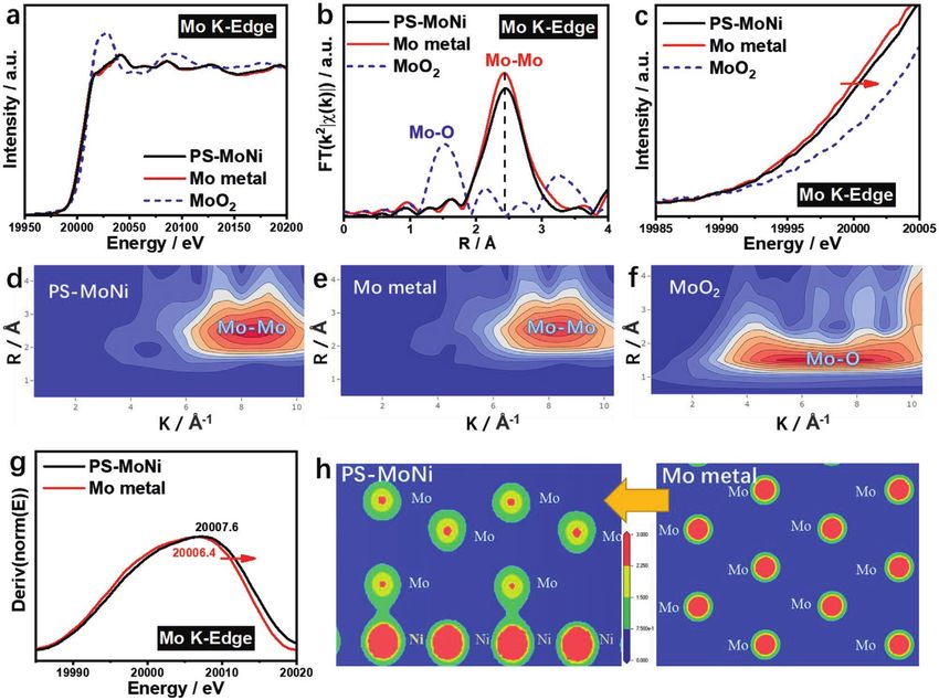
www.advancedsciencenews.com www.advenergymat.de Figure 1. a) Mo K-edge XAS of PS-MoNi obtained using Mo metal and MoO2 as references. b) The corresponding k2-weighted FT of EXAFS spectra at Mo K-edge in the R spacing of PS-MoNi, Mo metal, and MoO2. c) Mo K-edge XANES spectra of PS-MoNi, Mo metal, and MoO2. d–f) Wavelet trans- forms for the k2-weighted EXAFS signals at Mo K-edge of PS-MoNi, Mo metal, and MoO2. g) The first derivative of XANES at Mo K-edge of PS-MoNi and Mo metal. h) The electron density PS-MoNi and Mo metal. catalysts. Moreover, PS-MoNi shows excellent HOR activity in a the amorphous structure.[22] As shown in Figure 1b, for Mo large overpotential window of 0–0.32 V versus RHE, which is metal, the bond length of ≈2.4 Å at Mo K-edge in the R spacing more resistant to electrochemical oxidation than IC-MoNi. X-ray belongs to MoMo bond. For MoO2, the bond length of ≈1.5 Å absorption near edge structure (XANES) and density functional at Mo K-edge in the R spacing belongs to MoO bond. The cor- theory (DFT) calculations indicate the electron transfer from responding k2-weighted FT of EXAFS spectrum at Mo K-edge Mo to Ni. DFT calculations reveal that the electron deficiency in the R spacing of PS-MoNi is also basically the same as that of on Mo enhances the catalytic performance for reversible HER Mo metal and different from that of MoO2. Therefore, we infer and HOR by optimizing the ΔGH* of Mo. that the Mo element in PS-MoNi exists as phase-separated Mo PS-MoNi was synthesized on nickel foam by the hydro- metal. To confirm the electron transfer in the PS-MoNi, XANES thermal method and then the heat-treatment method at spectra at Mo K-edge of PS-MoNi, Mo metal, and MoO2 were 450 °C for 1 h in H2 atmosphere. IC-MoNi was synthesized in recorded. Figure 1c shows that the XANES spectrum at Mo K- the same way, but with a different concentration of solutions edge of PS-MoNi moves to a higher binding energy position (Figure S1, Supporting Information). XAS was usually used compared with Mo metal. This means that the phase-separated to characterize the structure of amorphous materials. The Mo metal loses electrons in the PS-MoNi. experiment data and simulation data of the corresponding k2- In the wavelet transform spectrum, the horizontal axis weighted Fourier transform (FT) of extended X-ray absorption shows the wave vector number k, which is the key to distin- fine structure (EXAFS) spectra at Mo K-edge in the R spacing guish different kinds of coordination atoms.[23] As shown in of PS-MoNi are shown in Figure S2 (Supporting Informa- Figure 1d–f, the coordination features of Mo in PS-MoNi are tion). As shown in Figure 1a, the XAS spectrum at Mo K-edge similar to those in Mo metal, with an intensity maximum at of PS-MoNi is basically consistent with that of Mo metal, and ≈2.4 Å and in the high-k part assigned to MoMo coordination. is different from MoO2. EXAFS is a powerful tool to study For MoO2, the high-intensity region was observed at ≈1.5 Å and Adv. Energy Mater. 2021, 2003511 2003511 (2 of 7) © 2021 Wiley-VCH GmbH
www.advancedsciencenews.com www.advenergymat.de Figure 2. a) Ni K-edge XAS of PS-MoNi obtained using Ni metal and NiO as references. b) The corresponding k2-weighted FT of EXAFS spectra at Ni K-edge in the R spacing of PS-MoNi, Ni metal, and NiO. c) The HRTEM and FFT patterns of the corresponding plane of PS-MoNi. d–f) Wavelet transforms for the k2-weighted EXAFS signals at Ni K-edge of PS-MoNi, Ni metal, and NiO. in the low-k part assigned to MoO coordination. An atom with is smaller than that of element Ni, which means that when Mo a small atomic number has a weak scattering ability for photo- and Ni metals are combined, Ni is more likely to attract elec- electrons, and its high-intensity region will appear in the low-k trons and cause electron transfer. part. An atom with a large atomic number is just the opposite, The XAS spectrum at Ni K-edge of PS-MoNi (Figure 2a) is and its intensity maximum will appear in the high-k part. In basically consistent with that of the Ni metal, and is different order to accurately analyze the electron density of Mo in the PS- from NiO. The corresponding k2-weighted FT of EXAFS spectra MoNi, the first derivatives of XANES at Mo K-edge of PS-MoNi at Ni K-edge in the R spacing of PS-MoNi, Ni metal, and NiO and Mo metal were recorded. As shown in Figure 1g, the max- are shown in Figure 2b. For Ni metal, the bond length of ≈2.2 Å imum value at Mo K-edge of amorphous PS-MoNi (20 007.6 eV) at Ni K-edge in the R spacing belongs to NiNi bond. For is bigger than that of Mo (20 006.4 eV). This means that the Mo NiO, the bond lengths of ≈1.7 and ≈2.6 Å at Ni K-edge in the R element loses electrons in the PS-MoNi. The electron transfer spacing belong to NiO and NiNi bonds, respectively. The cor- from Mo metal to the embedded Ni metal nanoparticles is responding k2-weighted FT of EXAFS spectrum at Ni K-edge in the key to the unique electronic structure and properties of the R spacing of PS-MoNi is also basically the same as that of Ni PS-MoNi, which are obviously different from those of pure metal and different from that of NiO. Therefore, we infer that Mo metal. the Ni element in PS-MoNi exists as Ni metal. Figure S6 (Sup- According to previous literature, amorphous modeling is porting Information) further shows the different metal-to-metal very difficult, so crystalline modeling is used to simplify cal- bond lengths for Mo (≈2.4 Å) and Ni (≈2.2 Å) in PS-MoNi, which culations.[24–27] To study the electron density modulation of means that Mo and Ni elements in PS-MoNi exist as Mo and amorphous Mo metal by embedded Ni metal nanoparticles, Ni metals, respectively. To demonstrate the morphologies and crystalline structures are used to model them. The optimized structures of the PS-MoNi, scanning electron microscopy (SEM) models of Mo metal (Figure S3, Supporting Information), Ni images of PS-MoNi are shown in Figure S7 (Supporting Infor- metal (Figure S4, Supporting Information), and PS-MoNi mation), and transmission electron microscopy (TEM) images (Figure S5, Supporting Information) were established in order of amorphous PS-MoNi are shown in Figure S8 (Supporting to calculate their electron density. Comparing the electron den- Information). The TEM images clarify the difference of struc- sity of PS-MoNi (Figure 1h, left) and the electron density of Mo tures between PS-MoNi (Figure S8, Supporting Information) and metal (Figure 1h, right), we can observe that the electrons of IC-MoNi (Figure S9, Supporting Information). The high resolu- Mo were transferred to Ni in PS-MoNi, which is consistent with tion transmission electron microscopy (HRTEM) and fast fourier the conclusions that we got from our experiments. In order transform (FFT) patterns of the corresponding planes are shown to reveal the nature of electron transfer more scientifically, in Figure 2c, which shows that it is an amorphous structure. Fur- we introduced the electronegativity of the elements for com- thermore, the EDS mappings (Figures S10 and S11, Supporting parison. We know that the element electronegativity reveals its Information) and the corresponding EDS spectra (Figure S12, ability to gain or lose electrons. The comparison of the electron- Supporting Information) demonstrate the uniform distribu- egativity of some transition-metal elements is shown in Table S1 tion of Ni nanoparticles (mass percent ≈ 18%) at the nanoscale (Supporting Information). The electronegativity of element Mo in PS-MoNi. In addition, Figure 2d–f shows that the Adv. Energy Mater. 2021, 2003511 2003511 (3 of 7) © 2021 Wiley-VCH GmbH

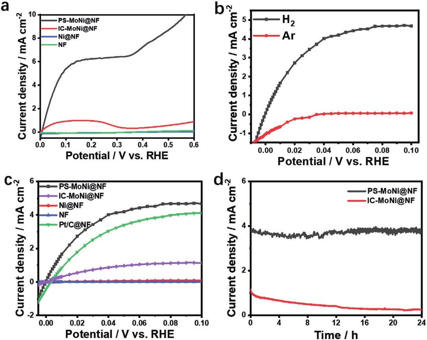
www.advancedsciencenews.com www.advenergymat.de coordination features of Ni in PS-MoNi are similar to those (Figure S16, Supporting Information), Ni metal (Figure S17, in Ni metal, with an intensity maximum at ≈2.2 Å and in the Supporting Information), and PS-MoNi (Figure 3a; Figure S18, high-k part assigned to NiNi coordination. For NiO, one high- Supporting Information) were also investigated by DFT calcula- intensity region was observed at ≈1.7 Å and in the low-k part tions. Because amorphous modeling is very difficult, crystalline assigned to NiO coordination, and the other high-intensity modeling is used to simplify calculations.[25–28] Figure 3b describes region was observed at ≈2.6 Å and in the high-k part assigned the ΔGH* on Mo and Ni sites in PS-MoNi compared with Mo and to NiNi coordination. The above experimental results illustrate Ni metals. Since the electrons of Mo were transferred to Ni in that we have synthesized amorphous Mo metal with embedded PS-MoNi, the ΔGH* of Mo site in PS-MoNi was increased to Ni metal nanoparticles (PS-MoNi). Figure S13a,b (Sup- −0.13 eV, very close to the Pt of −0.09 eV, which leads to the excel- porting Information) demonstrates the schematic diagrams of lent electrocatalytic performance in hydrogen electrochemistry. PS-MoNi and IC-MoNi alloys to distinguish them. Figure S13c Figure 3c exhibits the polarization curves of the PS- (Supporting Information) shows the corresponding k2-weighted MoNi@nickel foam (NF), IC-MoNi@NF, Ni@NF (Figures S19 FT of EXAFS spectra at Mo K-edge in the R spacing of PS-MoNi and S20, Supporting Information), NF, and Pt/C for HER in 1 m and Mo metal, compared with IC-MoNi, which further explains KOH solution. The PS-MoNi@NF exhibited extraordinary HER the difference between PS-MoNi and IC-MoNi.[16] To further activity and required an overpotential of only 30 mV to deliver a confirm the electron transfer in the PS-MoNi, Figure S14 (Sup- current density of −10 mA cm−2, which is comparable to excellent porting Information) demonstrates that the maximum value at non-noble catalysts (Table S2, Supporting Information).[20,29–40] It Ni K-edge of PS-MoNi (8332.8 eV) is smaller than Ni (8333.1 eV). also can be found the activity in HER of the PS-MoNi@NF is far It means the Ni in PS-MoNi obtains electrons. These analyses superior to the IC-MoNi@NF, which requires an overpotential further indicate that the electrons from amorphous Mo metal of nearly 76 mV to achieve the current density of −10 mA cm−2. are transferred to embedded Ni metal nanoparticles in PS-MoNi. To investigate the HER kinetics, the Tafel slope was calculated Comparing the electron density of PS-MoNi (Figure S15, left, in Figure S21 (Supporting Information). It can be found that Supporting Information) and the electron density of Ni metal PS-MoNi@NF electrode shows a low Tafel slope of 37 mV dec−1, (Figure S1, right, Supporting Information), we can observe that which means that the decrease in charge-transfer resistance embedded Ni metal nanoparticles obtain electrons in PS-MoNi, during the HER process accelerates HER kinetics.[41–43] We which is consistent with the conclusions that we got from our compare the Tafel slopes of PS-MoNi@NF and IC-MoNi@ experiments. NF, and it shows that the PS-MoNi@NF has a stronger A widely accepted cognition in hydrogen electrochemistry is response power than IC-MoNi@NF and reveals the reason that a high catalytic performance is anticipated if ΔGH* is close why PS-MoNi@NF has the better performance for HER. to 0 eV.[6,12,24,25] Therefore, hydrogen adsorptions on Mo metal Figure S22 (Supporting Information) shows the electrochemical Figure 3. a) Optimized models of PS-MoNi. b) Hydrogen adsorption free energy (ΔGH*) on the Mo metal, Ni metal, and PS-MoNi. c) LSV curves of PS-MoNi@NF, IC-MoNi@NF, Ni@NF, NF, and Pt/C@NF for HER were tested in 1 m KOH solution at 25 °C with a scan rate of 1 mV s−1. d) Chrono- amperometry curve of PS-MoNi@NF for HER at a constant current density of −100 mA cm−2 in 1 m KOH. Adv. Energy Mater. 2021, 2003511 2003511 (4 of 7) © 2021 Wiley-VCH GmbH
www.advancedsciencenews.com                                                                                                 www.advenergymat.de

Figure 4. a) LSV curves of PS-MoNi@NF, IC-MoNi@NF, Ni@NF, and NF were tested from 0 to 0.6 V versus RHE in 0.1 m KOH solution at 25 °C with
a scan rate of 1 mV s−1. b) The steady-state polarization curves of PS-MoNi@NF collected in H2-saturated and Ar-saturated 0.1 m KOH, respectively.
c) The steady-state polarization curves of PS-MoNi@NF, IC-MoNi@NF, Ni@NF, NF, and Pt/C@NF collected in H2-saturated 0.1 m KOH solution.
d) Chronopotentiometric curve of PS-MoNi@NF and IC-MoNi@NF for HOR at a constant potential of 0.1 V.

impedance spectroscopy Nyquist plots of PS-MoNi@NF,                           Figure 4b compares the steady-state polarization curves of
IC-MoNi@NF, Ni@NF, and NF, which also reveal that                          PS-MoNi @NF collected in H2-saturated (Figure S26, Sup-
PS-MoNi@NF has faster reaction kinetics in electrochemical reac-           porting Information) and Ar-saturated 0.1 m KOH solutions,
tions. For catalysts with excellent performance, stability during          respectively. The apparent anodic current at positive poten-
the reaction is indispensable. The chronopotentiometry curve of            tial versus RHE was obtained in the H2-saturated solution,
PS-MoNi@NF shows outstanding stability for HER at the current              which indicates that HOR takes place on PS-MoNi@NF.
densities of −10 mA cm−2 (Figure S23, Supporting Information) and          As plotted in Figure 4c, the HOR catalytic current density of
−100 mA cm−2 (Figure 3d). We also characterized the TEM images             PS-MoNi@NF takes off at 0 V versus RHE and is very close to
of the samples after the electrochemical stability test in Figure S24      that on Pt/C@NF in the potential window of 0−0.1 V versus
(Supporting Information). It can be seen that the structure is basi-       RHE. Compared with IC-MoNi@NF, the PS-MoNi@NF col-
cally unchanged compared to the sample before the stability test,          lected the larger current density signal at each corresponding
which further proves that the PS-MoNi has excellent stability.             potential. In addition, PS-MoNi@NF shows the excellent per-
   Linear sweep voltammetry (LSV) curve of PS-MoNi@NF, IC-                 formance in both H2-saturated 1 and 0.1 m KOH solutions
MoNi@NF, Ni@NF, and NF (Figure 4a) were tested from 0 to                   (Figure S27, Supporting Information).
0.6 V versus RHE in 0.1 m KOH solution. Excitingly, PS-MoNi@NF                To compare the intrinsic activity, the exchange current density
shows excellent activity in a large potential window of 0–0.32 V           was estimated based on the electric window region from −10 to
versus RHE due to the reactive Mo sites in PS-MoNi, which is               10 mV versus RHE.[44–46] Figure S25 (Supporting Information)
more resistant to electrochemical oxidation than Mo–Ni interme-            shows the i–t curve at each different voltage of PS-MoNi@NF.
tallic compound or Ni metal.[14–17] Therefore, the only possibility is     Figure S28 and Table S3 (Supporting Information) show that
that the active site of PS-MoNi is Mo site, which is in good agree-        the exchange current density of PS-MoNi@NF (4.883 mA cm−2)
ment with the previous experimental results and theoretical cal-           is 1.35 times higher than that of Pt/C@NF (3.615 mA cm−2)
culations. To test the stability of PS-MoNi@NF in reversible HER/          and 5.27 times higher than that of IC-MoNi@NF (0.916 mA cm−2),
HOR, the LSV curve of PS-MoNi@NF from −0.05 to 0.1 V versus                which are comparable to excellent non-noble catalysts.[6,12,27,47–49]
RHE in 0.1 m KOH solution at 25 °C with a scan rate of 1 mV s−1            To further investigate the stability of PS-MoNi@NF and
before and after stability testing was recorded in Figure S25              IC-MoNi@NF, the chronoamperometry at 0.1 V versus RHE
(Supporting Information). Excitingly, PS-MoNi@NF shows excel-              (Figure 4d) shows the stable current density. With the passage
lent stability in reversible HER/HOR.                                      of the test time, the performance of the IC-MoNi@NF has

Adv. Energy Mater. 2021, 2003511                                2003511 (5 of 7)                                           © 2021 Wiley-VCH GmbH
www.advancedsciencenews.com                                                                                                           www.advenergymat.de

been significantly attenuated, while the performance of the                       [7] T. Kou, M. Chen, F. Wu, T. J. Smart, S. Wang, Y. Wu, Y. Zhang, S. Li,
PS-MoNi@NF is still stable.                                                           S. Lall, Z. Zhang, Y. S. Liu, J. Guo, G. Wang, Y. Ping, Y. Li, Nat.
   In summary, we successfully synthesized the low-cost                               Commun. 2020, 11, 590.
PS-MoNi electrocatalyst for enhanced HOR and HER. Through                         [8] H. Jin, Q. Gu, B. Chen, C. Tang, Y. Zheng, H. Zhang, M. Jaroniec,
                                                                                      S. Z. Qiao, Chem 2020, 6, 2382.
tuning ΔGH* on Mo sites, PS-MoNi shows excellent activity
                                                                                  [9] H. Jin, X. Liu, S. Chen, A. Vasileff, L. Li, Y. Jiao, L. Song, Y. Zheng,
with the high exchange current density (−4.883 mA cm−2),                              S. Z. Qiao, ACS Energy Lett. 2019, 4, 805.
which is comparable to the reported highest value for non-noble                 [10] X. Wang, T. Ouyang, L. Wang, J. Zhong, T. Ma, Z. Liu, Angew. Chem.
catalysts. In comparison with the IC-MoNi, the PS-MoNi shows                          2019, 131, 13425.
both excellent activity and enhanced stability for HER and                       [11] F. Yang, X. Bao, Y. Zhao, X. Wang, G. Cheng, W. Luo, J. Mater.
HOR. Because the active site is Mo site, the breakdown poten-                         Chem. A 2019, 7, 10936.
tial of PS-MoNi is as high as 0.32 V, which is more resistant                   [12] F. Yang, X. Bao, P. Li, X. Wang, G. Cheng, S. Chen, W. Luo, Angew.
to electrochemical oxidation than IC-MoNi or Ni metal. This                           Chem. 2019, 131, 14317.
means that a PS-MoNi can enhance the power output and appli-                     [13] H. Zeng, S. Chen, Y. Q. Jin, J. Li, J. Song, Z. Le, G. Liang, H. Zhang,
cation potential of APEFC. Our work provides a facile strategy                        F. Xie, J. Chen, Y. Jin, X. Chen, H. Meng, ACS Energy Lett. 2020, 5,
                                                                                      1908.
for designing competent catalysts for HOR and HER.
                                                                                 [14] J. H. J. Wijten, R. L. Riemersma, J. Gauthier, L. D. B. Mandemaker,
                                                                                      M. W. G. M. (Tiny) Verhoeven, J. P. Hofmann, K. Chan,
                                                                                      B. M. Weckhuysen, ChemSusChem 2019, 12, 3491.
Supporting Information                                                          [15] S. Kabir, K. Lemire, K. Artyushkova, A. Roy, M. Odgaard,
                                                                                      D. Schlueter, A. Oshchepkov, A. Bonnefont, E. Savinova,
Supporting Information is available from the Wiley Online Library or                  D. C. Sabarirajan, P. Mandal, E. J. Crumlin, I. V. Zenyuk,
from the author.                                                                      P. Atanassov, A. Serov, J. Mater. Chem. A 2017, 5, 24433.
                                                                                [16] Y. Duan, Z. Y. Yu, L. Yang, L. R. Zheng, C. T. Zhang, X. T. Yang,
                                                                                      F. Y. Gao, X. L. Zhang, X. Yu, R. Liu, H. H. Ding, C. Gu, X. S. Zheng,
Acknowledgements                                                                      L. Shi, J. Jiang, J. F. Zhu, M. R. Gao, S. H. Yu, Nat. Commun. 2020,
                                                                                      11, 4789.
J.S. and Y.Q.J. contributed equally to this work. This work was supported by
the National Natural Science Foundation of China (Grant Nos. 21576301,           [17] C. R. Lee, S. G. Kang, J. Power Sources 2000, 87, 64.
22075102, and 22005120), the Natural Science Foundation of Guangdong            [18] W. Ni, A. Krammer, C. S. Hsu, H. M. Chen, A. Schüler, X. Hu,
Province, China (Grant No. 2017A030313048), and the Fundamental                       Angew. Chem., Int. Ed. 2019, 58, 7445.
Research Funds for the Central Universities (Grant No. 21619317).               [19] J. K. Nørskov, T. Bligaard, A. Logadottir, J. R. Kitchin, J. G. Chen,
                                                                                      S. Pandelov, U. Stimming, J. Electrochem. Soc. 2005, 152, J23.
                                                                                [20] J. Duan, S. Chen, C. A. Ortíz-Ledón, M. Jaroniec, S. Z. Qiao, Angew.
                                                                                      Chem., Int. Ed. 2020, 59, 8181.
Conflict of Interest                                                            [21] L. Wu, N. Y. Dzade, M. Yu, B. Mezari, A. J. F. Van Hoof, H. Friedrich,
The authors declare no conflict of interest.                                          N. H. De Leeuw, E. J. M. Hensen, J. P. Hofmann, ACS Energy Lett.
                                                                                      2019, 4, 1733.
                                                                                [22] G. Wu, X. Zheng, P. Cui, H. Jiang, X. Wang, Y. Qu, W. Chen, Y. Lin,
                                                                                      H. Li, X. Han, Y. Hu, P. Liu, Q. Zhang, J. Ge, Y. Yao, R. Sun, Y. Wu,
Data Availability Statement                                                           L. Gu, X. Hong, Y. Li, Nat. Commun. 2019, 10, 4855.
Research data are not shared.                                                   [23] Z. Xia, H. Zhang, K. Shen, Y. Qu, Z. Jiang, Phys. B 2018, 542, 12.
                                                                                [24] B. Zhang, X. Zheng, O. Voznyy, R. Comin, M. Bajdich, M. García-
                                                                                      Melchor, L. Han, J. Xu, M. Liu, L. Zheng, F. P. G. De Arquer,
                                                                                      C. T. Dinh, F. Fan, M. Yuan, E. Yassitepe, N. Chen, T. Regier, P. Liu,
Keywords                                                                              Y. Li, P. De Luna, A. Janmohamed, H. L. Xin, H. Yang, A. Vojvodic,
breakdown potential, hydrogen evolution reaction, hydrogen oxidation                  E. H. Sargent, Science 2016, 352, 333.
reaction, nonprecious metals, phase-separated alloys                            [25] X. Wang, Y. Zheng, W. Sheng, Z. J. Xu, M. Jaroniec, S. Z. Qiao,
                                                                                      Mater. Today 2020, 36, 125.
                                               Received: November 7, 2020       [26] Y. Jin, S. Huang, X. Yue, H. Du, P. K. Shen, ACS Catal. 2018, 8, 2359.
                                                  Revised: January 15, 2021     [27] J. Xu, C. Zhang, H. Liu, J. Sun, R. Xie, Y. Qiu, F. Lü, Y. Liu, L. Zhuo,
                                                         Published online:            X. Liu, J. Luo, Nano Energy 2020, 70, 104529.
                                                                                [28] F. Song, W. Li, J. Yang, G. Han, T. Yan, X. Liu, Y. Rao, P. Liao, Z. Cao,
                                                                                      Y. Sun, ACS Energy Lett. 2019, 4, 1594.
                                                                                [29] R. Zhang, X. Ren, S. Hao, R. Ge, Z. Liu, A. M. Asiri, L. Chen,
 [1] Y. Zhou, Z. Xie, J. Jiang, J. Wang, X. Song, Q. He, W. Ding, Z. Wei,             Q. Zhang, X. Sun, J. Mater. Chem. A 2018, 6, 1985.
     Nat. Catal. 2020, 3, 454.                                                  [30] S. Q. Liu, H. R. Wen, Y. W. Z. Ying-Guo, X. Z. Fu, R. Sun, C. P. Wong,
 [2] M. K. Debe, Nature 2012, 486, 43.                                                Nano Energy 2018, 44, 7.
 [3] P. Ganguly, M. Harb, Z. Cao, L. Cavallo, A. Breen, S. Dervin,               [31] H. Jin, X. Liu, Y. Jiao, A. Vasileff, Y. Zheng, S. Z. Qiao, Nano Energy
     D. D. Dionysiou, S. C. Pillai, ACS Energy Lett. 2019, 4, 1687.                   2018, 53, 690.
 [4] X. Wang, C. Xu, M. Jaroniec, Y. Zheng, S. Z. Qiao, Nat. Commun.            [32] Y. Zang, S. Niu, Y. Wu, X. Zheng, J. Cai, J. Ye, Y. Xie, Y. Liu, J. Zhou,
     2019, 10, 4876.                                                                  J. Zhu, X. Liu, G. Wang, Y. Qian, Nat. Commun. 2019, 10, 1217.
 [5] H. Jin, X. Liu, A. Vasileff, Y. Jiao, Y. Zhao, Y. Zheng, S. Z. Qiao, ACS   [33] Y. Liu, S. Liu, Y. Wang, Q. Zhang, L. Gu, S. Zhao, D. Xu, Y. Li, J. Bao,
     Nano 2018, 12, 12761.                                                            Z. Dai, J. Am. Chem. Soc. 2018, 140, 2731.
 [6] F. Song, W. Li, J. Yang, G. Han, P. Liao, Y. Sun, Nat. Commun. 2018,       [34] S. Deng, Y. Zhong, Y. Zeng, Y. Wang, Z. Yao, F. Yang, S. Lin,
     9, 4531.                                                                         X. Wang, X. Lu, X. Xia, J. Tu, Adv. Mater. 2017, 29, 1700748.

Adv. Energy Mater. 2021, 2003511                                     2003511 (6 of 7)                                                © 2021 Wiley-VCH GmbH
www.advancedsciencenews.com www.advenergymat.de
[35] Z. Chen, Y. Song, J. Cai, X. Zheng, D. Han, Y. Wu, Y. Zang, S. Niu, [42] C. Tang, R. Zhang, W. Lu, Z. Wang, D. Liu, S. Hao, G. Du,
Y. Liu, J. Zhu, X. Liu, G. Wang, Angew. Chem. 2018, 130, 5170. A. M. Asiri, X. Sun, Angew. Chem., Int. Ed. 2017, 56, 842.
[36] Q. Xu, Y. Liu, H. Jiang, Y. Hu, H. Liu, C. Li, Adv. Energy Mater. 2019, [43] Y. Li, H. Wang, L. Xie, Y. Liang, G. Hong, H. Dai, J. Am. Chem. Soc.
9, 1802553. 2011, 133, 7296.
[37] L. An, J. Feng, Y. Zhang, R. Wang, H. Liu, G. C. Wang, F. Cheng, [44] J. Zheng, W. Sheng, Z. Zhuang, B. Xu, Y. Yan, Sci. Adv. 2016, 2,
P. Xi, Adv. Funct. Mater. 2019, 29, 1805298. 1501602.
[38] Y. Wu, Y. Liu, G. D. Li, X. Zou, X. Lian, D. Wang, L. Sun, T. Asefa, [45] Y. Cong, B. Yi, Y. Song, Nano Energy 2018, 44, 288.
X. Zou, Nano Energy 2017, 35, 161. [46] S. Lu, Z. Zhuang, J. Am. Chem. Soc. 2017, 139, 5156.
[39] C. Zhu, A. L. Wang, W. Xiao, D. Chao, X. Zhang, N. H. Tiep, [47] Y. Yang, X. Sun, G. Han, X. Liu, X. Zhang, Y. Sun, M. Zhang, Z. Cao,
S. Chen, J. Kang, X. Wang, J. Ding, J. Wang, H. Zhang, H. J. Fan, Y. Sun, Angew. Chem. 2019, 131, 10754.
Adv. Mater. 2018, 30, 1705516. [48] T. Wang, M. Wang, H. Yang, M. Xu, C. Zuo, K. Feng, M. Xie,
[40] X. Peng, A. M. Qasim, W. Jin, L. Wang, L. Hu, Y. Miao, W. Li, Y. Li, J. Deng, J. Zhong, W. Zhou, T. Cheng, Y. Li, Energy Environ. Sci. 2019,
Z. Liu, K. Huo, K. yin Wong, P. K. Chu, Nano Energy 2018, 53, 66. 12, 3522.
[41] Y. Li, X. Tan, S. Chen, X. Bo, H. Ren, S. C. Smith, C. Zhao, Angew. [49] Z. Zhuang, S. A. Giles, J. Zheng, G. R. Jenness, S. Caratzoulas,
Chem., Int. Ed. 2019, 58, 461. D. G. Vlachos, Y. Yan, Nat. Commun. 2016, 7, 10141.
Adv. Energy Mater. 2021, 2003511 2003511 (7 of 7) © 2021 Wiley-VCH GmbHYou can also read