Physical Layer Test System (PLTS) 2021 - Keysight
←
→
Page content transcription
If your browser does not render page correctly, please read the page content below
Physical Layer Test System (PLTS) 2021
Data Collection & Analysis Software for Frequency and Time Domain Data with
Optional Instrument Control (Includes What’s New in PLTS 2021)
Why is Physical Layer Testing Required?
The next generation computer and communication systems now being developed will
handle data rates of multiple gigabits/second. Many systems will incorporate processors
and SERDES chip sets that exceed Gigahertz clock frequencies. New and troubling
input/output issues are emerging as switches, routers, server blades, and storage area
networking equipment moving toward 10 Gbps data rates. Digital design engineers
choosing chip-to-chip and backplane technologies for these systems are finding signal
integrity challenges that have not been encountered before.

Traditional parallel bus topologies are running out of bandwidth. As parallel busses
become wider, the complexity and cost to route on PC boards increase dramatically. The
growing skew between data and clock lines has become increasingly difficult to resolve
within parallel busses. The solution is fast serial channels. The newer serial bus structure
has quickly replaced the parallel bus structure for high-speed digital systems. Engineers
have been turning to a multitude of gigabit serial interconnect protocols with embedded
clocking to achieve the goal of simple routing and more bandwidth per pin. However, these
serial interconnects bring their own set of problems.

In order to maintain the same total bandwidth as the older parallel bus, the new serial bus
needs to increase its data rate. As the data rate increases through serial interconnects, the
rise time of the data transition from a zero-logic level to a one logic level becomes shorter.
This shorter rise time creates larger reflections at impedance discontinuities and degrade
the eye diagram at the end of the channel. As a result, physical layer components such as
printed circuit board traces, connectors, cables, and IC packages can no longer be
ignored. In fact, in many cases, the silicon is so fast that the physical layer device has
become the bottleneck.

Find us at www.keysight.com                                                                      Page 1

In order to maintain signal integrity throughout the complete channel, engineers are moving away from single-
ended circuits and now use differential circuits. The differential circuit provides good Common Mode Rejection
Ratio (CMRR) and helps shield adjacent PCB traces from crosstalk. Properly designed differential
transmission lines will minimize the undesirable effect of mode conversion and enhance the maximum data
rate throughput possible. Unfortunately, differential signaling technology is not always an intuitive science.

Differential transmission lines coupled with the microwave effects of high-speed data have created the need
for new design and validation tools for the digital design engineer. Understanding the fundamental properties
of signal propagation through measurement and post measurement analysis is mandatory for today’s leading-
edge telecommunication and computer systems. The traditional Time Domain Reflectometer (TDR) is still a
very useful tool, but many times the Vector Network Analyzer (VNA) is needed for the complete
characterization of physical layer components. There is a strong need for a test and measurement system
that will allow simple characterization of complex microwave behavior seen in high speed digital
interconnects. In fact, many digital standards groups have now recognized the importance of specifying
frequency domain physical layer measurements as a compliance requirement.

Both Serial ATA and PCI Express have adopted the SDD21 parameter (input differential insertion loss) as a
required measurement to ensure channel compliance (Figure 3). This parameter is an indication of the
frequency response that the differential signal sees as it propagates through the highspeed serial channel. An
example of a proposed SDD21 compliance mask is shown in Figure 1 for the Channel Electrical Interface
(CEI) working group for the Optical Internetworking Forum (OIF).

Figure 2. Today’s digital standards are now using frequency domain measurements for compliance testing, such
as this input differential insertion loss (SDD21) mask for XAUI

Find us at www.keysight.com                                                                               Page 2
A single test system can provide the total view
As the combination of both time-domain and frequency domain analysis becomes more important, the
need for multiple test systems becomes difficult to manage. A single test system that can fully
characterize differential high-speed digital devices, while leaving domain and format of the analysis up to
the designer, is a very powerful tool. Keysight’s Physical Layer Test System (PLTS) is designed
specifically for this purpose.

PLTS has been designed specifically for signal integrity analysis. PLTS software guides the user through
hardware setup and calibration and controls the data acquisition. It automatically applies patented
transformation algorithms to present the data in both frequency and time domains, in both forward and
reverse transmission and reflection terms, and in all possible modes of operation (single ended,
differential, and mode-conversion).

A powerful virtual bit pattern generator feature allows a user-defined binary sequence to be applied to
the measured data to convolve eye pattern diagrams. Next, highly accurate RLCG models can be
extracted and used to enhance the accuracy of your models and simulations. While PLTS is
predominantly an R&D tool, a SCPI interface with a rich set of commands enables remote and
manufacturing applications. Also, manufacturing applications benefit from the custom characterization
report inside PLTS that allows users to document all multi-domain data required automatically.

PLTS provides design confidence through complete characterization
Physical-layer structures have increasingly become the bottleneck in high-speed digital system
performance. At low data rates, these interconnects are electrically short. The driver and receiver are
typically the biggest contributors to signal integrity. But as clock speeds, bus speeds, and link speeds all
push past the gigabit-per-second mark, physical layer characterization becomes more critical. These
interconnects become microwave transmission lines and need to be characterized carefully to avoid
internet infrastructure failure.

Another challenge for today's digital designers is the trend to differential topologies. Fully understanding
device performance requires analysis in all possible modes of operation

Figure 3. A differential structure operates in many modes. Single-ended analysis can reveal sources of
asymmetry on this differential transmission line.

Find us at www.keysight.com                                                                                    Page 3

Time-domain analysis is typically used for characterization of these physical-layer structures, but often,
the designer concentrates only on the intended modes of operation. For a complete time-domain view,
step and impulse responses in reflection and transmission (TDR and TDT) must be seen. The analysis
must include the unintended modes of operation as well.

Frequency-domain analysis, again in all possible modes of operation, is also necessary for fully
characterizing these physical-layer structures. The s-parameter model describes the analog behavior
exhibited by these digital structures. This behavior includes reflections from discontinuities, frequency
dependent losses, crosstalk, and EMI performance.

For translating device performance into standards compliance, eye diagrams add an important statistical
analysis. And for leveraging this complete characterization into improved simulations, measurement-
based s-parameter or RLCG model extraction completes the picture.

                                                          Time Doman                         Frequency Domain

                   Mode                            TDR                 TDT            Reflection         Transmission

 Differential                                     TDD11                TDD21             SDD11               SDD21
                                                  TDD22                TDD12             SDD22               SDD12
 Diff-to-comm                                     TCD11                TCD21             SCD11               SCD21
                                                  TCD22                TCD22             SCD22               SCD12

 Comm to diff                                     TDC11                TDC21             SDC11               SDC21
                                                  TDC22                TDC12             SDC22               SDC12

 Common                                           TCC11                TCC21             SCC11               SCC21
                                                  TCC22                TCC12             SCC22               SCC12
 Single-ended                                       T11            T21 T31 T41            S11             S21 S31 S41
                                                    T22            T12 T32 T42            S22             S12 S32 S42
                                                    T33            T13 T23 T43            S33             S13 S23 S43
                                                    T44            T14 T24 T34            S44             S14 S24 S34

Figure 4. Complete characterization includes forward and reverse transmission and reflection, in all
possible modes of operation, in both frequency and time domains
1. An RLCG equivalent circuit model, also known as Telegrapher’s Parameters, describes the electrical behavior of a
   passive transmission line. The model is a distributed network consisting of series resistance and inductance (R and L)
   and parallel capacitance and conductance (C and G).

Find us at www.keysight.com                                                                                                 Page 4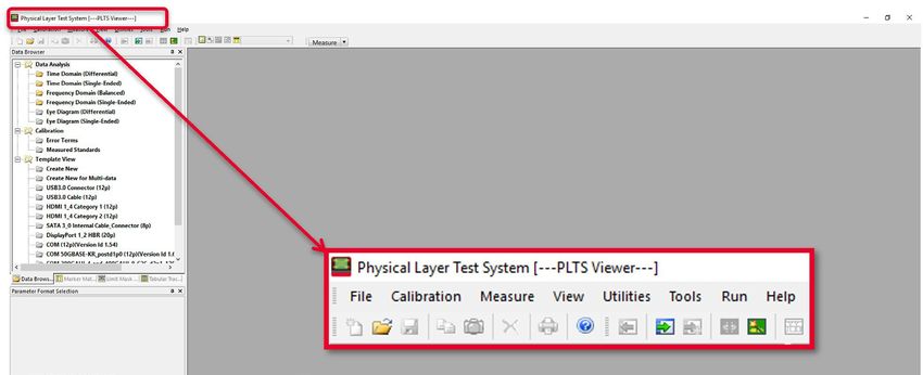
PLTS enables mode-conversion analysis for early insight into EMI problems
The benefits of differential signaling include lower voltage swings, immunity from power supply noise, a
reduced dependency on RF ground, and improved EMI performance (reduced generation and
susceptibility). The extent to which a device can take advantage of these benefits is directly related to
device symmetry.

Symmetric devices only respond to, and only generate, differential signals. These ideal devices do not
respond to or generate common-mode signals, and they reject radiated external signals (i.e., power
supply noise, harmonics of digital clocks or data, and EMI from other RF circuitry).

Asymmetric devices, however, do not exhibit these benefits. When stimulated differentially, an
asymmetric device will produce a common-mode response in addition to the intended differential
response, and cause EMI radiation. Conversely, with a common-mode stimulus, an asymmetric device
will produce an unintended differential response. This mode conversion is a source of EMI susceptibility.

Mode-conversion analysis is an important tool for understanding and improving device symmetry
and provides the designer with early insight to identify and resolve EMI problems at the design stage
(Figure 5).

                                                                                               “PLTS 2021 is used
                                                                                               in many high-speed
                                                                                               digital applications
                                                                                               worldwide including
                                                                                               Gigabit Ethernet,
                                                                                               Fibre Channel,

                                                                                               USB Type-C, PCIe,
                                                                                               DDR, HDMI, SATA,
                                                                                               Thunderbolt and
                                                                                               many more.”
Figure 5. Asymmetric devices cause mode-conversions, which are indicators of
EMI generation and susceptibility.

Mode conversion
A practical application of how mode conversion helps identify problems in physical layer devices is
shown in Figure 5. This shows a XAUI backplane with two daughter cards that typically transmit data at
3.125 Gbps. The design objective for this high-speed differential channel is to minimize the crosstalk
between adjacent differential PCB traces throughout the length of the channel. The channel consists of
the linear passive combination of the backplane and two daughter cards. Any mode conversion from
differential mode to common mode will generate EMI and create crosstalk that will be incident upon
other channels and will degrade performance. However, locating the exact structure within the channel
that creates the most mode conversion is not simple.

Find us at www.keysight.com                                                                                 Page 5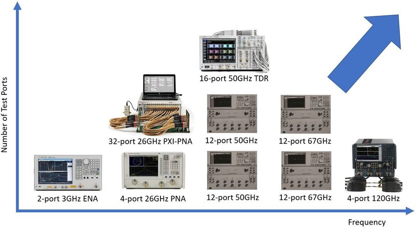
Looking at figure 6, the differential to common mode conversion time domain reflection parameter
(TCD11) is time aligned with the differential impedance profile of the channel (TDD11) below it. A marker
is placed on the largest magnitude peak of TCD11. This is where the physical structure within the
channel is creating the most mode conversion and thus the source of the most crosstalk. We can align
the TDD11 to the TCD11 in time and therefore co-locate the problematic structure on TDD11. To relate
this structure to the channel, we use the differential impedance profile as a reference. From previous
analysis, we know that the two capacitive discontinuities on TDD11 are the daughter card via field and
motherboard via field, respectively. Since the marker falls upon the second discontinuity on TDD11, it is
deduced that the motherboard via field is the biggest culprit to causing crosstalk in adjacent channels.
This shows how identifying the mode conversion in a channel can be intuitive with proper analysis.

Figure 6. By aligning the impedance profile with the mode conversion profile, PLTS allows the
pinpointing of crosstalk-generating structures within physical layer devices.

Remove unwanted effects from the measurement
Error correction
Over the years, many different approaches have been developed for removing the effects of the test
fixture from the measurement (shown in Figure 7). The level of difficulty for each error correction
technique is linearly related to the accuracy of each method. Time domain gating is perhaps the simplest
and most straightforward method, but it is also the least accurate. Likewise, de-embedding is the most
complicated method, but it is the most accurate. It is important to have a test system that will allow
flexibility of choosing the method of error correction desired for each application

Error correction techniques fall into two fundamental categories: direct measurement (pre-measurement
processing) and de-embedding (post-measurement processing). Direct measurement requires
specialized calibration standards that are connected to the end of a coaxial test cable and measured.
The accuracy of the device measurement relies on the quality of these physical standards. De-
embedding uses a model of the test fixture and mathematically removes the fixture characteristics from
the overall measurement. This fixture de-embedding procedure can produce very accurate results.

Find us at www.keysight.com                                                                                 Page 6
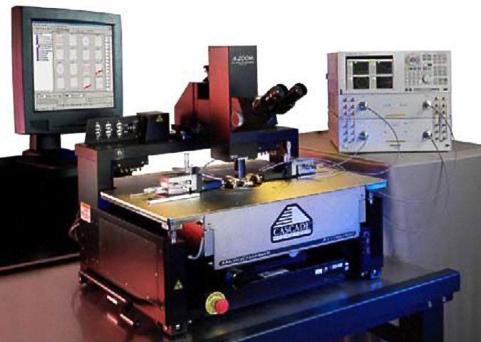
Figure 7. PLTS has advanced error correction techniques to allow flexibility for many applications

Port Extension (also known as Phase Rotation) mathematically extends the calibration reference plane
to the DUT.

This technique is easy to use but assumes the fixture – the unwanted structure – looks like a perfect
transmission line: a flat magnitude response, a linear phase response, and constant impedance. If the
fixture is very well designed, this technique can provide good results.

Because gating essentially considers the magnitude of the unwanted discontinuity, and
Port Extensions consider phase (electrical length), using the two tools together may
provide optimum results.

Time-domain gating (Figure 7) is like port extension, in that it is also very easy and fast. The user simply
defines two points in time or distance, and the software mathematically replaces the actual measured
data in that section with data representing an "ideal" transmission line. The return loss is then
recalculated to show the effects of the change in the frequency domain.
One practical application of time-domain gating is as a confidence check before replacing a suspect
connector.

Figure 8 illustrates how this technique might be used.

De-embedding (Figure 9) uses an accurate linear model of the fixture, or measured s-parameter data of
the fixture. This fixture data can then be removed mathematically from the DUT measurement data in
post-processing.

Find us at www.keysight.com                                                                                    Page 7
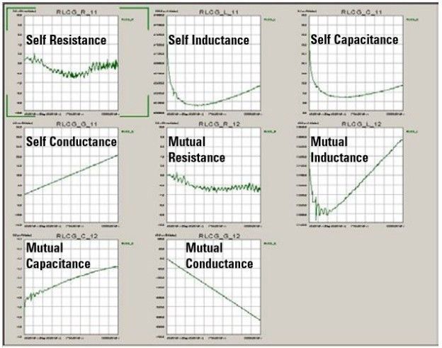
Figure 8. In this rather extreme example of time-domain gating, the top plots show the measured
differential step impedance and return loss. The lower left plot shows a gate added to remove the large
discontinuity in the center of the trace. On the lower right, the measured and the recalculated return
losses are displayed. In this case, the gate improved the return loss by more than 10 dB within the
frequency band of interest.

Calibration at the DUT reference plane has the advantage that the precise characteristics of the fixture
do not need to be known beforehand, as they are measured and corrected for during the calibration
process.

An example of this technique is microprobing using a calibration substrate, where the calibration
reference plane is established at the probe tips, rather than at the end of the coaxial test cables.

Advanced calibration techniques (TRL/LRM) –originally developed for wafer probing applications –
provide additional options

Automatic Fixture Removal (AFR)
As shown in figure 7, Automatic Fixture Removal is the most accurate method of de-embedding a test
fixture with the most ease-of-use. Keysight invented this technology years ago and continues to improve the
AFR algorithm to enhance accuracy. The latest version of AFR inside accounts for such subtle effects as
mode conversion within a poorly designed test fixture. For additional details in this innovative de-embedding
method, please refer to our Technical Document entitled, “The ABC’s of AFR” found in the PLTS Technical
Library here: www.keysight.com/find/plts.

Find us at www.keysight.com                                                                                Page 8
Figure 9. The effects of test fixtures can be removed from the device in post-processing through de-
embedding.

Figure 10. A microprobing application, where the calibration is performed using an impedance standard
substrate, establishes the calibration reference plane at the probe tips.

Find us at www.keysight.com                                                                             Page 9
PLTS Support for Microprobing Applications
Keysight works closely with leading microprobe and
probe station suppliers to provide the best complete
system solutions possible.
One of the most significant measurement challenges is
connectivity. Test equipment provides a controlled
coaxial environment, but what if the DUT – the
backplane, the interface connector, the IC package –
is non-coaxial?
Test fixtures can provide the required connectivity, but
at a cost. The quality of the test fixture – its
connectors, impedance discontinuities, parasitics, and Figure 11. Cascade Microtech’s Summit probe
dielectric losses – all contribute to less than ideal station
performance of the fixture. Subsequently, the accuracy
of the device measurement is degraded.
Several techniques are available to remove these
fixture effects (see Remove Unwanted Effects from the
Measurement on page 6), but the accuracy of these
techniques is greatly impacted by the quality of the
fixture itself, or the availability of an accurate s-
parameter model of the fixture (used for de-
embedding). Microprobing can offer the user the ability
to forego the test fixture and launch the stimulus
directly at the device input. The response can be
measured directly at the device output. Additionally,
when calibration substrates are available, calibration
can be performed directly at the probe tips. This
achieves co-location of the calibration reference plane
with the device measurement reference plane.
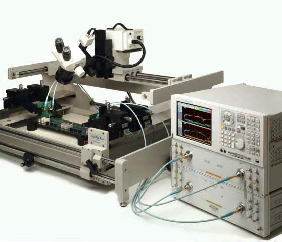
Figure 12. GigaTest lab’s GT-4060 probe station
PLTS has the flexibility to accommodate many
microprobe configurations. By adding the calibration
substrate coefficients as a calibration kit, the process
becomes as straightforward as a coaxial calibration.
Find us at www.keysight.com Page 10PLTS Simplifies the Measurement Process
Device characterization with PLTS software is
straight-forward. The user interface has been
designed to make setup, calibration, and
measurement intuitive and error-free. A wizard guides
the user through all the required steps. The last
prompt is to connect the device under-test and initiate
the measurement. Setup and calibration differ slightly
between TDR-based and VNA based systems.
However, in both cases the PLTS software provides
an intuitive wizard to assist in the step-by- step
process.
Figure 13. PLTS has a three-step system
set up to make measurements intuitive
and error-free
Data analysis with n-port PLTS
File and view management with the Time domain analysis: Frequency domain analysis:
data browser – 2 n2 parameters – 2 n2 parameters
– 7 formats – 8 formats
– time or distance
Format, scaling, and marker Plot and trace Eye diagram analysis: RLCG model extraction
control with easy access management with context- – n2 parameters – 2 n2 parameters
toolbars sensitive parameter – 8 formats
buttons
Find us at www.keysight.com Page 11Data analysis Frequency-domain analysis
All supported analysis types and formats are available The mixed-mode frequency domain is
immediately after the measurement is completed, and another common starting point.
at any time thereafter. PLTS flexibility allows the user Initially, sixteen parameters are displayed in
to begin where they are most familiar. thumbnail view as shown below. These thumbnails
represent four modes of device operation: differential,
Time-domain analysis common- mode, and the two mode-conversion types
The mixed-mode time domain is a common starting (common- mode stimulus with differential response
point. Initially, sixteen parameters are displayed in and differential stimulus with common-mode
thumbnail view as shown below. These thumbnails response). A double mouse-click on any of these
represent four modes of device operation: differential, thumbnails will expand the selected parameter to full
common-mode, and the two mode-conversion types screen for close analysis.
(common-mode stimulus with differential response and
differential stimulus with common-mode response). A Not shown here are the additional sixteen single-
double mouse click on any of these thumbnails will ended frequency-domain parameters.
expand the selected parameter to full screen for closer
analysis.
Not shown here are the additional sixteen single-
ended time-domain parameters.
Figure 15. The mixed-mode frequency-domain
matrix.
Figure 14. The mixed-mode time-domain matrix
Find us at www.keysight.com Page 12Measurement-based eye diagram analysis Using the built-in digital pattern generator, the user can define virtual bit pattern (as wide as 2^32-1 bits). PLTS then convolves the selected bit pattern with the device impulse response to create an extremely accurate measurement-based eye pattern diagram. This eliminates the need for a hardware pulse/pattern generator, and its flexibility allows for a great deal of "What if…" analysis. Figure 16. The digital pattern generator. After the eye pattern is generated, marker functions can be used to make typical measurements like jitter, eye opening, rise and fall times, and more. Figure 17. Eye pattern diagram. Find us at www.keysight.com Page 13
Multi-channel Simulation
The standard PLTS eye diagram is using an ideal data source (no jitter, no noise) to simulate the
overlapped waveform data of the NRZ (non-return-zero) signals as well as PAM4 signals transmitted
through the measured backplane channel. To add advanced eye diagram capabilities, PLTS has a
powerful feature to modify the Tx (transmitter) and Rx (receiver), and to add Xtalk (crosstalk) and inject
jitter effects to simulate real world applications. This multi-channel simulation can quickly and efficiently
simulate the following conditions:

•   Specify bit pattern settings for data sources (either Tx or Xtalk) – Inject jitter to the data sources, the
    jitter includes RJ (random jitter), PJ (periodic jitter) and ISI (inter-symbol interference or so-called
    Dirac jitter)
•   Add source noise by specifying SNR (signal-to-noise ratio per symbol).
•   Add source equalization (the same meaning with pre-emphasis/de-emphasis).
•   Add Rx multiple equalization types of CTLE, FFE, and DFE) (automatically or specify the taps manually).
•   Add Xtalk effects from sources on other ports.
•   Import IBIS-AMI models for TX and RX for advanced channel analysis
PLTS uses MATLAB to add jitter, noise, Tx and Rx equalization in this fashion: PLTS invokes a
MATLAB dynamic link library in the background for doing the multi-channel eye simulation. For this
feature, only the MATLAB Compiler Runtime (MCR) needs to be installed, and that has been included in
PLTS install package.

      Ytalk1
                    Jitter     Noise

      PRBS                                  EQ

      Tx                                                                          Jitter

                    Jitter     Noise

                                                                                                 Rx

     PRBS                       ∑           EQ                                                        EQ

                                                              Channel
     YtalkN
                    Jitter     Noise

     PRBS                                   EQ

Figure 18. Multi-Channel Simulation is a fast and simple simulation engine specifically designed for high speed digital
interconnect channels. It allows quick results with a minimal learning curve yet provides powerful
capabilities with full transmitter and receiver customization. Even IBIS-AMI models of transmitters and
receivers are utilized for application specific chipset analysis.

Find us at www.keysight.com                                                                                       Page 14
In Channel Operating Margin (COM)
As emerging standards become more complex for signal integrity engineers, the tools they use in the SI
laboratory must become equally sophisticated. Such revolutionary test and measurement capabilities are
now inside the PLTS platform with the additional of Channel Operating Margin (COM). Simply put, the
COM MATLAB-based subroutine is automatically run in the background of PLTS based on a standardized
configuration spreadsheet defined by the IEEE standards. This enables the design engineer to make
component trade-offs inside a given channel design to optimize interoperability. The COM tool in PLTS
takes a half-day testing procedure and turns it into a 10-15 minute measurement driven automatically with
a graphical user interface. An example of the COM output from PLTS is shown below.
Received Signal
Figure 19. Channel Operating Margin (COM) testing inside PLTS platform enables design engineer to
make interoperability trade-off studies to maximize performance/cost ratio in high speed digital channels.
Find us at www.keysight.com Page 15PLTS Simplifies the Measurement Process
Multi-channel eye diagram configuration: including
1. Detailed functionalities
the DUT configuration and the channel setup. The
Open or import a data set ([DEMO] E8364B 12-port 10
channel setup includes the information on which
MHz-20 GHz. dut for example) and view the data in
ports the Tx, Rx and Xtalks are added and the
frequency domain single-ended analysis mode, then go
detailed settings of the Tx, Rx and Xtalks.
to the eye diagram view (either differential or single-
ended). Now the menu of -> is enabled. dependent on a specific DUT configuration, if you
select another data set with a different DUT
configuration, this window will automatically update
the multi-channel eye diagram configurations that
match the current DUT configuration in the list. This
also means you can use one configuration to
simulate the eye diagrams of many data sets with
the same DUT configuration.
From the Buttons you can Add, Delete, Rename,
Save, Load configurations.
Figure 20. To activate Multi-Channel Simulation mode,
select it from the Tools Menu. 1.1 Channel setup
The simulation channels can be set up by dragging
Click on the menu and the window below pops up: Tx, Rx and Xtalk components to specific slots. To
start the simulation, there must be one Tx, one Rx,
0~N Xtalks. In the configuration below, a
transmission channel of SDD43 and two Xtalk
channels of SDD41 and SDD45 were set up.
Figure 21. Main dialog box for Multi-Channel Simulation
mode.
Figure 22. Near-end and far-end crosstalk
simulation is simple and fast.
Find us at www.keysight.com Page 161.2 Tx Settings
Click on the added Tx module (blue button) or right-click on it and select “Edit”, one can change the Tx
settings.
a. Ports - specify which port this module is
added on. If you change the port number,
the module will be moved to the new port
specified.
b. Pattern - bit pattern settings.
c. Jitter - timing jitter is defined as the
deviation of a signal’s timing clock from
the ideal clock. Timing jitter can be
divided into two main subcategories:
deterministic and random jitter.
d. Equalization - in serial data transmission,
pre-emphasis/ de-emphasis is often used
to compensate for losses over the
channel which is larger at higher
frequencies. The high frequency content
is emphasized compared to the low
frequency content which is de-
emphasized. This is a form of transmitter
equalization.
Figure 23. Transmitter and Receiver settings can be
edited for pre-emphasis, jitter injection, noise
injection, and multitude of equalization types.
RLCG model extraction
RLCG (resistance, inductance, capacitance, and
conductance) models describe the electrical behavior of
passive transmission lines in an equivalent circuit model.
From the measured S-parameters of a device, PLTS
calculates the R, L, C, G, complex propagation constant,
and complex characteristic impedance.
This provides a highly accurate, measurement-based
coupled transmission line model for export into modeling
and simulation software such as Keysight ADS,
Synopsis HSPICE, and others.
Figure 24. RLCG model extraction (W-Element
shown).
Find us at www.keysight.com Page 17PLTS Signal Integrity Solutions Portfolio
For all hardware configurations see PNA Family Microwave Network Analyzers Configuration Guide,
part number 5992-1465EN.
PLTS Ordering Guide
PLTS system requirements
To ensure that PLTS operates effectively, your PC should have the following minimum requirements:
Measurement mode ONLY Off-Line analysis mode
In the lab, controlling test equipment and In your office, performing “What if ….”
making quick analysis of the results Analysis characterization, cross-domain
analysis, filtering, waveform math, and eye
diagram simulation.
CPU 1.5 GHz Quad-core 1.5 GHz Quad-core
4 GB 4+ GB
Main memory (RAM)
Virtual memory – As a general
rule, virtual memory should be 1.5
6 GB+ 6 GB+
to 2 times the size of main
memory
GPIB interface Keysight 82357A USB/GPIB Interface for No GPIB connection is required to use PLTS
With PLTS 4.2 PLTS can connect Windows or supported GPIB card (any off-line.
to a PNA over LAN National Instruments or Keysight Saved (stored) measurement files can be
82340/41 or 82350 GPIB Card) recalled at any time for analysis
Operating systems Windows 10 only Windows 10 only
Screen resolution 1280 x 1024 or greater required 1280 x 1024 or greater required
Display colors High color (16 Bit) or greater High color (16 Bit) or greater
Find us at www.keysight.com Page 18VNA support²
The following Keysight vector network analyzers are
supported by PLTS 2021 Firmware selection may depend
on CPU and model number:
(http://na.support.keysight.com/pna/cputype.html)
• All PNA (N522xA/B) Series
• All PNA-X (N524xA/B) Series
• All PNA MM-Wave (N5290/91A)
• M980XA PXI-VNA
• P50xxA series USB-VNA
• E5080B Series VNA
• E5061B OPT. xL5 (Power Integrity)
• 86100C TDR with Flex DCA
• M937x PXI series
• N523xA/B PNA-L series
• E5080A ENA series
For the most up-to-date recommended firmware, please go
to the Keysight PNA Firmware Support website at
http://na.support.keysight.com/pna/firmware/firmware.htm
E5071C-PLTS Compatibility Guide
The E5071C VNA is partially supported by PLTS 2021 software. The E5071C can be controlled,
calibrated and measured remotely from PLTS software running on an external laptop. All the standard
post-processing capability is available such as multi-domain analysis. However, there are some
limitations. See list below.
1. PLTS 2021 does not support E5071C measurement collection through Option 5 (advanced
calibration with Automatic Fixture Removal). However, AFR can be accomplished with the E5071C
if the user imports the S-parameter data in manually. This support strategy is similar to the 86100
DCA’s limitations with PLTS.
2. The E5071C does not support N-port calibration through PLTS software.
3. PLTS requires that the ENA have firmware A.08.00 or higher
Find us at www.keysight.com Page 19PLTS Legacy vs. New Cross Reference Matrix
Legacy Description New
N1930B-1FP PLTS Base Analysis Fixed License N19301B-1FP
N1930B-1NP PLTS Base Analysis Networkable N19301B-1NP
License
N1930B-1TP1,2,3 PLTS Base Analysis Transportable N19301B-1UP
(USB) License
N1930B-1TY1,2,3 PLTS Base Analysis Transportable N19301B-1UL
(USB) 12-month License
N1930B-3FP PLTS Measurement and Calibration N19303B-1FP
Fixed License
N1930B-3NP PLTS Measurement and Calibration N19303B-1NP
Networkable License
N1930B-3TP1,2,3 PLTS Measurement and Calibration N19303B-1UP
Transportable (USB) License
N1930B-3TY1,2,3 PLTS Measurement and Calibration N19303B-1UL
Transportable (USB) 12-month License
N1930B-5FP PLTS Advanced Calibration Fixed N19305B-1FP
License
N1930B-5NP PLTS Advanced Calibration N19305B-1NP
Networkable License
N1930B-5TP1,2,3 PLTS Advanced Calibration N19305B-1UP
Transportable (USB) License
N1930B-5TY1,2,3 PLTS Advanced Calibration N19305B-1UL
Transportable (USB) 12-month License
N1930B-6FP PAM-4 analysis fixed license N19306B-1FP
N1930B-6NP PAM-4 analysis networkable license N19306B-1NP
N1930B-6TP1,2,3 PAM-4 analysis transportable (USB) N19306B-1UP
License
N1930B-6TY1,2,3 PAM-4 analysis Transportable (USB) N19306B-1UL
12-month license
N1930B-7FP PLTS N-Port Measurement and N19307B-1FP
Analysis Fixed License
N1930B-7NP PLTS N-Port Measurement and N19307B-1NP
Analysis Networkable License
N1930B-7TP1,2,3 PLTS N-Port Measurement and N19307B-1UP
Analysis Transportable (USB) License
N1930B-7TY1,2,3 PLTS N-Port Measurement and N19307B-1UL
Analysis Transportable (USB) 12-month
License
Notes
1. Previous "Transportable" license was USB dongle based. In the new structure it is a USB portable license
2. There are now subscription licenses for 6, 12, 24, and 36 months
3. Subscription licenses are also available for Network, USB, and the new Transportable license types
Find us at www.keysight.com Page 20Important notes regarding PLTS software configuration
1. If PLTS Studio is used (PLTS N19301B this will allow data analysis of files up to and including 4
ports (*s4p Touchstone files). However, if data is to be analyzed from files containing more than 4
ports (for example, 12-port data from a *s12p Touchstone file), the appropriate PLTS multiport option
must be purchased (PLTS N19307B)
2. The VNA firmware options 550 or 551 must be ordered in conjunction with PLTS to work properly as
a calibration and measurement system. Option 550 is for applications of 4 ports or less, while option
551 is for applications greater than 4 ports.
3. PLTS N19301B is required for N19303B, N19305B, N19306B, or N19307B.
4. PLTS has an annual support called Keysight Care Software Support Subscription. Each new PLTS
license must be accompanied by a support subscription (12, 24 or 36 months). Before the original
support subscription expires, a new support subscription must be purchased. Depending how long
the product is off support, there is a penalty to re-add support.
5. PLTS N19303B is required for instrument control portions of N19305B. As noted in 3 above, PLTS
N19301B is required for either N19303B, N19305B, N19306B, or N19307B
6. PNA firmware is updated frequently and the newer PNA firmware version has backward compatibility
and works well with the latest PLTS software.
Find us at www.keysight.com Page 21Software Terms, Types and KeysightCare Software Support Subscriptions
Keysight software Licensing options provide flexibility and support
Projects ramp up and down, teams grow and shrink, and projects move location. In such a dynamic
environment, you need flexible licensing options that allow you to balance your project’s requirements.
Whether your software will be a staple for years to come or you have a short-term need for a leading-
edge measurement application, Keysight’s licensing puts you in charge.
Choose your term. Choose your type. Keep control of your budget.
• Select a node-locked, transportable, USB portable or floating license type, depending on how
much flexibility you need.
• Select a subscription or perpetual license term, depending on how long you need to use
the software.
• Each license is sold with a KeysightCare software support subscription which provides technical
support with ensured response time, proactive software updates, enhancements and fixes.
Choose a license term and type that best suits your requirements from the table below.
Table 1. License Terms
License Term Options
Perpetual Perpetual licenses can be used indefinitely.
Subscription Subscription licenses can be used through the term of the license (6, 12, 24, or 36 months).
Table 2. License Type
License Type Descriptions
Node locked License can be used on one specified instrument/computer.
Transportable License can be used on one instrument/computer at a time but may be transferred to another
using Keysight Software Manager (internet connection required).
USB portable License can be used on one instrument/computer at a time but can be transferred to another
using a certified USB dongle (available for additional purchase, Keysight part number E8900-
D10).
Floating Networked instruments/computers can access a license from a server one at a time. Multiple
licenses may be purchased for concurrent usage. Three types of floating license are
available:
Single Site: 1-mile radius from the server
Single Region1: Americas, Europe, Asia
Worldwide (export restriction identified in End User License Agreement (EULA))
1. Americas (North, Central, and South America, Canada); Europe (European Continent, Middle Eastern Europe, Africa, India); Asia
(North and South Asia, Pacific Countries, China, Taiwan, Japan)
Find us at www.keysight.com Page 22KeysightCare software support subscription provides peace of mind amid evolving technologies.
• Ensure your software is always current with the latest enhancements and measurement standards.
• Gain additional insight into your measurement problems with live access to our team of technical
experts.
• Stay on schedule with fast turnaround times and priority escalations when you need support.
Table 3. KeysightCare software support subscription
Subscription Description
Perpetual licenses are sold with a 12 (default), 24, 36, or 60-month software support
KeysightCare subscription. Support subscriptions may be renewed for a fee after that.
software support Subscription licenses include a software support subscription through the term
subscription of the license.
Ordering Information
• Step 1. Choose your software product.
• Step 2. Choose your license term: perpetual orsubscription.
• Step 3. Choose your license type: node-locked, transportable, USB portable, or floating.
• Step 4. Depending on the license term, choose your support subscription duration.
License Term
Product License Type Perpetual Subscription
License Support Subscription License & Support Subscription
Node-locked (fixed) R-A5G-001-A + R-A6G-001-z R-A4G-001-z
Transportable R-A5G-004-D + R-A6G-004-z R-A4G-004-z
N1930xB USB Portable1 R-A5G-005-E + R-A6G-005-z R-A4G-005-z
Floating (single site) R-A5G-002-B + R-A6G-002-z R-A4G-002-z
Floating (single region) R-A5G-006-F + R-A6G-006-z R-A4G-006-z
Floating (worldwide) R-A5G-010-J + R-A6G-010-z R-A4G-010-z
z = subscription duration z = subscription duration
L 12 months (default)2 F 6 months
X 24 months L 12 months
Y 36 months X 24 months
Z 60 months Y 36 months
1. USB portable license requires a certified USB dongle (available for additional purchase, Keysight part number E8900-D10)
2. For S93xxxB software, the fixed-perpetual with a 12-months, support subscription (R-A6A-001-L) is the only license type
that can be ordered as part of the instrument and installed. The other license types for S93xxxBs and all license types for
S94601B/2B must be ordered separately and installed from the web after the receipt of the instrument.
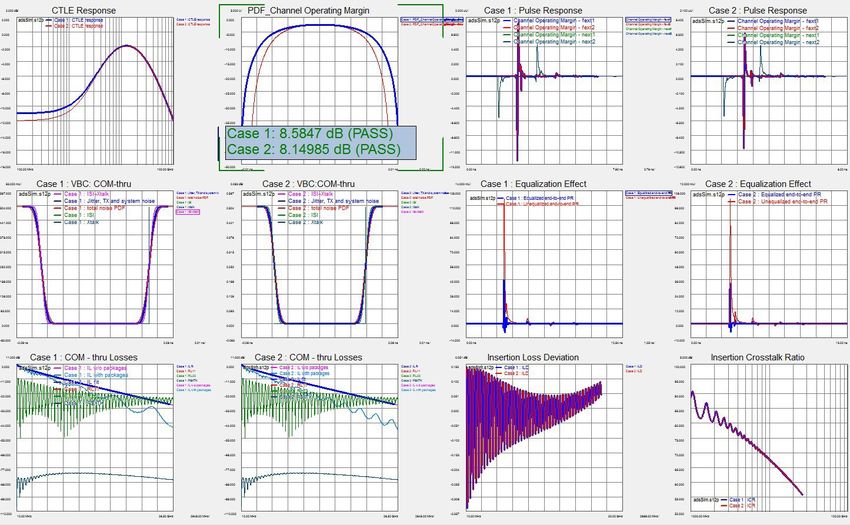
Find us at www.keysight.com Page 23What’s New with PLTS 2021? Offline S-parameter data viewer Many signal integrity engineers want to view basic s-parameters in a user-friendly environment without accessing capital expenditure funding from their management teams. Budget cycles are not always fast, predictable or guaranteed approval, so the PLTS project team has created an offline freeware version of PLTS to accommodate these demands. The new PLTS 2021 Offline Viewer can import s- parameters and allow basic analysis in a quick and easy format. While many advanced features are not enabled, there is still plenty of useful features such as panels marker math definitions and tabular trace data. Signal integrity engineers using the PLTS Viewer will be pleased to know that many of the plot menus are still enabled, including the complete plot tool panel. See picture below. Disaggregation with parallel multi-threading The advent of hyperscale data centers and the 800G architecture have both driven the data rates to extreme levels within the internet infrastructure. Large s-parameter files and complex figures-of-merit requiring heavy computational load has created a need for more powerful data analysis. This is the challenge facing many signal integrity engineers measuring s-parameters of interconnects and computing Channel Operating Margin (COM), Insertion Loss Deviation (ILD), Insertion Crosstalk Ratio (ICR), Voltage Bathtub Curve and CTLE Response that possibly involve hundreds of channels. PLTS 2021 has incorporated data disaggregation and multi-threading processes that allow faster number crunching using parallel architecture. This enables COM to run in the background and allows alternate data analysis in the foreground, thus reducing overall time required for troubleshooting interconnect designs. Another side benefit of disaggregation is speeding up the batched file converter process and batched reference plane adjustment. Graphical User Interface enhancements Listening closely to our installed base of loyal customers around the world, the PLTS R&D team has incorporated many requested enhancements to improve the overall usability of this world class signal integrity software platform. Automatic de-skew, automatic AFR mode conversion, improved resolution of marker display, and increased the maximum number of open files from 100 to 1000, to name just a few. Our hard-working team is committed to the future of this signal integrity application and growing the feature set every year in order to create value for each and every user of PLTS. Find us at www.keysight.com Page 24
Learn more at: www.keysight.com
For more information on Keysight Technologies’ products, applications or services,
please contact your local Keysight office. The complete list is available at:
www.keysight.com/find/contactus

Find us at www.keysight.com                                                                                                                Page 40
This information is subject to change without notice. © Keysight Technologies,2018-2021, Published in USA, February 3, 2021, 5992-3233EN
You can also read