PLIDCO HALF WELD ENDS - INSTALLATION INSTRUCTIONS ENGLISH SPANISH
←
→
Page content transcription
If your browser does not render page correctly, please read the page content below
PLIDCO® HALF WELD ENDS
                             INSTALLATION INSTRUCTIONS

                                                LANGUAGES:
                                CLICK ON LANGUAGE DESIRED

                                                        ENGLISH
                                                        SPANISH

PLIDCO – The Pipe Line Development Company
www.plidco.com | (440) 871-5700 | pipeline@plidco.com
11792 Alameda Drive, Strongsville, OH 44149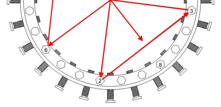
The Pipe Line Development Company
11792 Alameda Drive, Strongsville, Ohio 44149, USA
Phone: (440) 871-5700 • Fax: (440) 871-9577
Toll Free: 1-800-848-3333
web: www.plidco.com • e-mail: pipeline@plidco.com
PLIDCO® HALF WELD+END
INSTALLATION INSTRUCTIONS
!! WARNING!!
IMPROPER SELECTION OR USE OF THIS PRODUCT CAN RESULT IN
EXPLOSION, FIRE, DEATH, PERSONAL INJURY, PROPERTY DAMAGE
AND/OR HARM TO THE ENVIRONMENT.
READ CAREFULLY
The person in charge of the installation must be familiar with these instructions and communicate them
to all personnel involved. Do not use or select a PLIDCO Half Weld+End until all aspects of the
application are thoroughly analyzed. Do not use the PLIDCO Half Weld+End until you read and
understand these installation instructions. Every effort has been made to securely package this product
prior to shipment. Thoroughly inspect for any damage that may have occurred during shipment. If you
have any questions, or encounter any difficulties using this product, please contact:
PLIDCO 440-871-5700
Safety Check List
Read and follow these instructions carefully. Follow your company’s safety policy and applicable
codes and standards.
Whenever a PLIDCO product is modified in any form including changing seals by anyone other than
the Engineering and Manufacturing Departments of The Pipe Line Development Company or a
PLIDCO certified repacking company, the product warranty is voided. Products that are field
modified do not have the benefit of the material traceability, procedural documentation, quality
inspection and experienced workmanship that are employed by The Pipe Line Development
Company.
During the Pipe Preparation for Mechanical End and Installation procedures, those installing the
PLIDCO Half Weld+End must wear, at minimum, Z87+ safety eyewear and steel toe safety
footwear.
Be absolutely certain that the correct seal material has been selected for the intended use. Contact
PLIDCO or an authorized PLIDCO distributor if there are any questions about the seal compatibility
with the pipeline chemicals and temperatures.
Page 1 of 13 IP-048
Revision 1
Determine the type of joint that the PLIDCO Half Weld+End is expected to connect. See (a) and
(b) below and determine the appropriate maximum allowable operating pressure (MAOP) from the
ratings listed on the label of the PLIDCO Half Weld+End.
(a) Pipe Unanchored
A PLIDCO Half Weld+End is considered “Unanchored” only if it is installed with the clamp and
thrust screws, and not welded to the pipe or installed with any other appropriate means of
limiting pipe movement and end pull forces.
(b) Anchored Pipe
A PLIDCO Half Weld+End is considered “Anchored” if it is welded to the pipe line, or the end
pull forces are restricted by other means.
The total end pull rating of an Unanchored PLIDCO Half Weld+End is primarily determined by the
ability of the clamp screws to resist the PLIDCO Half Weld+End from being pulled off of the pipe.
The rating is provided in terms of pressure. The force can be calculated from the following equation.
Any combination of forces beyond the unachored rating can cause the fitting to slide or slip off the
pipe. Those forces include, but are not limited to: pressure spikes caused by re-pressurizing the
pipe too quickly causing an impact load, earth loading such as earthquakes, vibration, gravity loads
by supporting large sections of pipes, thermal stresses, excessive pressure beyond the unanchored
rating, bending moments, etc.
Pipe wall thickness less than those listed may be pushed inward by the force of the clamp screws.
Contact PLIDCO for the recommended maximum allowable operating pressure and revised clamp
screw torque values for pipe wall thicknesses thinner than listed in Table 1.
Minimum Pipe Wall Thickness for a PLIDCO Half Weld+End
Nominal Pipe Size (inches) Wall Thickness (inches)
1½ 0.200 (5.1 mm)
2 0.218 (5.5 mm)
2½ 0.276 (7.0 mm)
3 0.237 (6.0 mm)
4 0.237 (6.0 mm)
6 0.280 (7.1 mm)
8 0.322 (8.2 mm)
10 0.365 (9.3 mm)
12 0.406 (10.3 mm)
14 0.438 (11.1 mm)
16 & larger 0.500 (12.7 mm)
Table 1
A PLIDCO Clamp+Ring should be considered whenever the wall thickness is less than those listed.
A PLIDCO Clamp+Ring should also be considered where high external forces (such as underwater
currents or thermal contractions) are anticipated, even if the pipe has an adequate wall thickness.
Page 2 of 13 IP-048
Revision 1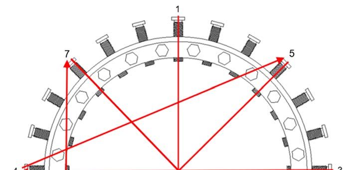
Pipelines should be carefully supported or restrained at elbows and bends to prevent pullouts
caused by internal and external forces; or a PLIDCO Clamp+Ring should be used. The pipeline
should be evenly supported before re-pressuring. Follow applicable B31 codes during re-
pressuring.
If the PLIDCO Half Weld+End is welded according to our instructions, or a suitable PLIDCO
Clamp+Ring is used, it can be considered an anchored joint.
Observe the pressure and temperature ratings on the label of the PLIDCO Half Weld+End. Re-
pressuring should be accomplished slowly and steadily without surges that could vibrate the pipeline
and fitting. Industry codes and standards are a good source of information on this subject. Except
for testing purposes, do not exceed the design pressure of the PLIDCO Half Weld+End. Refer to
the Field Testing section for precautions. Personnel should not be allowed near the installation until
the seal has been proven.
Accurate clamp screw torque values are very important when the PLIDCO Half Weld+End is used
on a pipeline joint that is UNANCHORED. DO NOT exceed the Pipe Unanchored rating listed on
the label of the PLIDCO Half Weld+End until subsequent welding has been completed or the pipe
is anchored by other means, such as a PLIDCO Clamp+Ring. FAILURE TO DO SO CAN RESULT
IN EXPLOSION, FIRE, DEATH, PERSONAL INJURY, PROPERTY DAMAGE AND/OR HARM TO
THE ENVIRONMENT.
Configuration
The configuration of the Half Weld+End consists of a socket weld assembly on one end and a mechanical
connection with a single clamp & thrust screws on the other end. Unless otherwise stated, these
instructions are to be used in applications where the Half Weld+End is welded as a socket joint on one
end and a mechanical connection on the other end as shown in Figure 1.
Note: Figure 1 does not represent all applications of a Half Weld+End.
Figure 1
Page 3 of 13 IP-048
Revision 1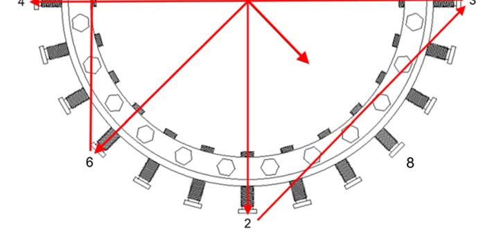
Socket Weld Joint Attachment

Typically, the socket weld end of the Half Weld+End is pre-weld to the spool piece, cap, or flange prior
to attaching the mechanical connection end to the existing pipe line. The assembly is then slid over the
existing piping where the mechanical connection is made. The following instructions detail this
procedure.

1.   The pipe end of the spool piece must be cut reasonably square.
2.   Any longitudinal, circumferential, or spiral weld must be removed where the Half Weld+End will slide
     over the end of the spool piece. In-addition, all welds must be ground flush where the fillet weld is
     to be applied on the socket end.
3.   The location of the spool piece attachment to the Half Weld+End must be carefully welded to ensure
     that the seal lands on smooth pipe and there is adequate room for the pipe that will be inserted into
     the mechanical end. The seal should have a minimum of ½” (12.7mm) – 1” (25.4mm) from the start
     of the pilot bevel as shown in Figure 2.

                                                                             Mechanical Connection
                                                                                     End

                                                Figure 2

4.   It is recommended to remove the elastomeric seal to avoid damaging the seal while welding the
     Half Weld+End to the spool piece. When replacing the seal after welding, it must be positioned on
     the inside of the metal thrust ring. Also note the placement of the radius on the seal as shown in
     Figure 2. DO NOT place the seal back in until the fitting has cooled down to under 100° F.
5.   Weld the Half Weld+End to the spool piece using an appropriate welding code, such as API 1104,
     and a qualified weld procedure for making the external fillet weld. The size of the weld leg should
     be at least 1½ times the pipe wall thickness.

                                              Page 4 of 13                                         IP-048
                                                                                                Revision 1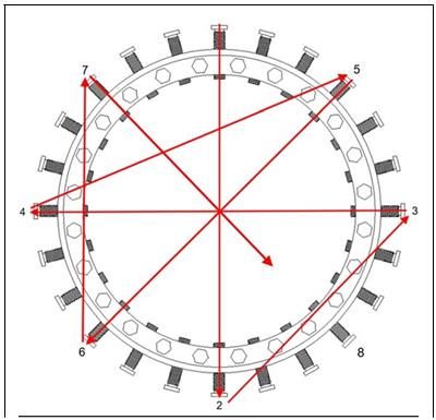
Pipe Preparation for the Mechanical End

1.   The existing pipe end should be cut reasonably square with any sharp ends or burrs removed. A
     generous taper or pilot bevel is recommended for misaligned or out-of-round pipe to allow for easy
     assembly as shown in Figure 2.
2.   The pipe surface underneath the Half Weld+End needs to be cleaned. Large debris, coatings, and
     burrs should be removed to allow the fitting to easily slide over the pipe.
3.   The area around the location where the seal will come into contact with the pipe must have a finer
     cleaning. A near-white finish, as noted in SSPC-SP10 / NACE No.2, is preferred in and around the
     seal area as shown in Figure 3. The cleaner the pipe surface, the more positive the seal. Any
     longitudinal, circumferential, or spiral weld must be ground flush with the OD of the pipe where the
     Half Weld+End will slide over the end of the existing pipe. It is recommended to clean the pipe at
     least 1” past the end of the fitting as shown in figure 3.

                                                Figure 3
4.   The seals can tolerate minor surface irregularities of up to ± 1/32 inch (0.8 mm). High weld
     reinforcement or steeply sided welds will need to be ground flush with the pipe outside diameter
     surface.
5.   Pipe outside tolerance is as follows:
      Nominal pipe size 6-inch and smaller; ± 1% of the nominal diameter
      Greater than 6-inch through 14-inch; + 1/16 inch (1.6 mm), - 1/8 inch (3.2 mm)
      Greater than 14-inch nominal diameter; ± 5/32 inch (4.0 mm)

                                             Page 5 of 13                                          IP-048
                                                                                                Revision 1
Mechanical Installation

The seals can be damaged by careless handling. Lifting devices such as chains, cables or lift truck forks
shall not contact the seals. Failure to prevent contact with the seals can result in the seals being
damaged or pulled from their grooves.
1.   Measure and record the inside distance to the seal; dimension “A” as shown in Figure 4. This will
     be needed later if the mechanical end of the Half Weld+End is to be fully welded to the pipe.

                                                 Figure 4
2.   Coat all exposed surfaces of the seal material with a lubricant. Table 2 indicates the lubricants that
     are recommended for the various seal materials. The customer must determine if the lubricant is
     compatible with the product in the pipeline. Fittings using braided packing DO NOT require any
     lubrication.
                   Petroleum based lubricants       =A
                   Silicone based lubricants        =B
                   Glycerin based lubricants        =C
                   Super Lube® Grease (1)           =D
                                                               Temperature (2)
                   Buna-N                        A, B, C, D     225°F (107°C)
                   Viton                         A, B, C, D     250°F (121°C)
                   Silicone                      C, D           300°F (149°C)
                   Neoprene                      B, C, D        250°F (121°C)
                   Aflas                         A, B, C, D     225°F (107°C)
                   Hycar                         A, B, C, D     180°F (82°C)
                  (1) Super Lube® Grease is a product of Synco Chemical
                      Corporation. (www.super-lube.com)

                   (2) Temperature limit is for the seal material only and does not
                       imply the pressure rating is necessarily applicable at this limit.

                                                Table 2

     NOTE: Do not use a lubricant for underwater applications. Sand, silt, or debris could adhere to the
     lubricant affecting the sealing ability and the accuracy of the torque values.

                                               Page 6 of 13                                         IP-048
                                                                                                 Revision 1
3. Slide the Half Weld+End with the pipe to which it is welded over the end of the pipe to which it will
be mechanically joined until it bottoms out on the welded pipe. Then back the Half Weld+End away
from the welded pipe approximately 1/16 inch as shown in Figure 2. Note that the end of the pipe
or the start of the pilot bevel on the mechanical end must be beyond the seal groove by 1/2 inch to
1 inch as shown in Figure 2.
Note: It can be helpful to measure the distance from the end of the Half Weld+End to the end of the
seal, and marking the location where the Half Weld+End will land prior to installing.
4. Determine which clamp screw size is being used, measure the diameter of the threaded end of the
clamp screw (measured in inches). As noted in the Safety Check List, contact PLIDCO for the
maximum allowable operating pressure and the revised clamp screw torque value for thin wall pipe.
5. Center the PLIDCO Half Weld+End to the pipe. Advance the clamp screws to obtain equal spacing
and stick out between the inner diameter of the Half Weld+End and the outside diameter of the pipe.
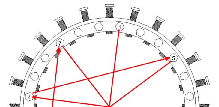
6. Clamp screws must be tightened evenly, maintaining an equal space between the pipe and the
coupling using the recommended torque values. Tighten the clamp screws one at a time (torque
values in Table 3) in a repeated sequence that matches Figure 5. The first time through the
sequence, tighten the screws to 25% of the minimum torque. The second time through, tighten the
screws to 50% minimum torque. The third time through, tighten the screws at 100% torque. Then,
repeat the sequence at 100% torque until the clamp screws are unable to continue spinning (see
Table 4 for torque percentage for each sequence).
Wrench Cup Point Minimum Number of Times Percentage of
Opening Torque Through Torque Minimum Torque
Across Clamp Sequence
Flats Screws (ft-lbf) (Nm) 1 25%
(inches) (inches)
2 50%
15/16 5/8-11 100 136
3 100%
1 3/4-10 150 204
4+ (Circular 100%
Table 3 Sequence)
Table 4
Page 7 of 13 IP-048
Revision 1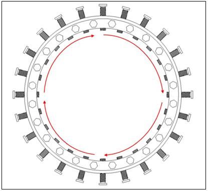
Figure 5

  Figure 6

Page 8 of 13      IP-048
               Revision 1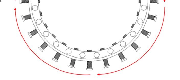
7.   Snug all the thrust screws firmly and evenly around the circumference, while maintaining an equal
     stick out from the end of the Half Weld+End.

8.   Torque the thrust screws one at a time (torque values in Table 5) in a repeated crisscrossed star
     sequence that matches Figure 7. The first time through the sequence, tighten at 25% of the
     minimum torque. The second time through, at 50% of the minimum torque. The third time through,
     at 100% of the minimum torque. Then, follow a circular tightening sequence, that matches Figure
     8, at 100% torque, until the thrust screws are unable to continue spinning (see Table 4 for torque
     percentage for each sequence).

                   Wrench Opening       Thrust Screws            Torque Range
                     Across Flats      Nominal Diameter
                                                              (ft-lbf)     (Nm)
                       (inches)            (inches)
                         7/16               3/8-16           20 - 25      28 - 34
                         9/16               1/2-13           30 - 40      41 - 55
                        13/16               5/8-11           70 - 80      95 - 109
                                               Table 5

                                               Figure 7

                                            Page 9 of 13                                         IP-048
                                                                                              Revision 1
Figure 8
Re-pressuring and Field Testing
If the pipeline has been shut down, re-pressuring should be done with extreme caution. Re-pressuring
should be accomplished slowly and steadily, without surges that could vibrate the pipeline or produce a
sudden impact load that could pull the fitting off the pipe. Industry codes and standards are a good
source of information on this subject.
Except for testing purposes, do not exceed the MAOP of the PLIDCO fitting. The PLIDCO fitting is
designed to be tested up to 1½ times its design pressure. For hydrotesting, PLIDCO recommends
following API Recommended Practice 2201, Procedures for Welding or Hot Tapping on Equipment in
Service, Section 6.5. The test pressure should be at least equal to operating pressure of the line or
vessel, but not to exceed internal pressure by 10%. This is meant to avoid possible internal collapse of
the pipe or vessel wall. However, if prevailing conditions could cause collapse of the pipe or pressure
walls, the test pressure may be reduced. (See API Standard 510 Section 5.8 for pressure testing
precautions.) Personnel should not be allowed near the repair until the seal has been proven.
Page 10 of 13 IP-048
Revision 1Field Welding Instruction of the Mechanical End
Welding is not a requirement for the pressure sealing ability of the PLIDCO Half Weld+End.
The issue of welding is dependent on your company’s requirements, applicable codes, and
if longitudinal loads exceed the rating of the clamp screws.
!! WARNING!!
Failure to follow field welding instructions could result in explosion, fire, death, personal injury, property
damage and/or harm to the environment.
All of the aspects for in-service welding of PLIDCO Half Weld+End are not addressed by this
document. ASME PCC-2, API 1104 Appendix B, ASME Section IX, PRCI L52047, PRCI Hot Tap®
Model, and other industry information pertaining to in-service welding must be considered when
planning in-service welding. Refer to IP-019, Welding Considerations for addition information.
It is recommended that the pipeline should be full and under flow.
Welders and weld procedures should be qualified in accordance with API Standard 1104, Welding of
Pipelines and Related Facilities, Appendix B, In-Service Welding. We strongly recommend the use of a
low hydrogen welding process such as GMAW or SMAW, using low hydrogen electrodes (E-XX18)
because of their high resistance to moisture pick-up and hydrogen cracking. SMAW electrodes must be
absolutely dry. It is very important that the field welding procedure closely follow the essential variables
of the qualified procedure, so that the quality of the field weld is represented by the mechanical tests
performed for the procedure qualification.
Use weld material with equal or greater tensile strength than the pipe. Carefully control the size and
shape of the circumferential fillet welds. The weld is required to anchor the joint and give longitudinal
stability to the pipeline. The size of the fillet weld should be at least 1.4 times the wall thickness of the
pipe. This assumes a 1.0 joint efficiency. You may need to select a different joint efficiency based on
your level of inspection or your company’s welding policy.
Strive for a concave-faced fillet weld, with streamlined blending into both members; avoid notches and
undercuts. The smoother and more streamlined the weld, the greater the resistance to fatigue failure.
The worst possible shape would be a heavy reinforced convex weld with an undercut. Improper weld
shape can lead to rapid fatigue failure, which can cause leakage, rupture, or an explosion, with potentially
serious consequences.
It is very important that the field welding procedure closely follow the essential variables of the qualified
procedure, so that the quality of the field weld is represented by the mechanical tests performed for the
procedure qualification.
We do not recommend the use of thermal blankets for pre-heating. Thermal blankets can generate hot
spots and reduce the ability of the PLIDCO Half Weld+End to dissipate welding heat in the vicinity of the
seals. We recommend a small torch, such as a cutting torch, being careful not to aim the flame directly
into the gap between the PLIDCO Half Weld+End and the pipe towards the seals. The flame from a
preheat torch is helpful in burning off oils and other contaminates. Do not use a large torch, commonly
called a rosebud, because of the difficulty controlling the size of the area being preheated.
During welding the temperature around the seals must be monitored. Dimension “A”, as measured during
the initial installation, should now be used to mark off location “B”, as shown in Figure 4. To prevent
damage to the seals, monitor the heat generated by welding or preheating, particularly at location “B”,
by using temperature crayons or probe thermometers. If the heat generated approaches the temperature
limit of the seal material, which is indicated in the seal lubrication chart, welding should be discontinued
or sequenced to another part of the fitting so that the affected area has a chance to cool.
Page 11 of 13 IP-048
Revision 1The clamp and thrust screws of PLIDCO Half Weld+Ends are specially fabricated studs. They are
made from mild carbon steel to increase weldability.
Welding Sequence
Caution should be observed so that welding or preheating does not overheat the seals. Sequence the
welding so that the heat is not concentrated in one area.
1. Cut thrust screws so they are flush with the PLIDCO Half Weld+End. (See Figure 9)
Figure 9
2. Add a fillet weld to the end of the Half Weld+End around the circumference of the pipe, and seal
weld the End of the cut off thrust screws. (See Figure 9)
3. After the circumferential fillet welds are finished, one clamp screw per end may be removed to serve
as a vent while welding the remaining clamp screws and also as a final test point for leakage if so
required. Cut or burn off the clamp screws approximately 3/16” (4.8 mm) above the outside surface
of the fitting and seal weld. (See Figure 10)
Page 12 of 13 IP-048
Revision 1Figure 10
For information on optional hydrotesting of the welds before putting into service, read IP-053,
(CLAMP SCREW TEST PORT INSTALLATION INSTRUCTIONS). Contact PLIDCO for additional
information.
4. If one clamp screw was removed for venting and/or hydrotesting, reinsert the clamp screw and seal
weld the screw to the body after testing is completed.
Storage Instructions
PLIDCO Half Weld+Ends should be stored in a dry environment to prevent the unpainted surfaces from
rusting. Storage temperatures should not exceed 120ºF (50ºC). Cover with a tarp made of dark
polyethylene, box, etc. to keep the direct sunlight away from the seals. It is best to exclude
contamination, light, ozone and radiation. Improperly stored PLIDCO Half Weld+Ends can cause the
gasket material to become cracked and brittle and lose its ability to seal.
Traceability
PLIDCO Half Weld+Ends, as with most PLIDCO products, have a unique serial number by which the
fitting is fully traceable. Additionally, all elastomer seals have a unique batch number by which the seal
material is traceable.
Recommended Inspection Schedule
1. After the pipeline is re-pressurized and field tested, (see Re-pressuring and Field Testing for
precautions) the torque values should be checked again 4 hours after installation. Then, the torque
values should be checked again 24 hours after that.
NOTE: This is only applicable for non-welded applications.
2. It is recommended that torque striping be applied from the threads of all the screws to the body of
the PLIDCO Half Weld+End so that any loosening of the screws can be visually seen during an
inspection.
NOTE: This is only applicable for non-welded applications.
3. 6 months after installation it is recommended that a visual inspection occurs that checks for visible
signs of leakage, bolt/nut loosening, and general wear or corrosion.
4. After the 6-month inspection occurs, a yearly visual inspection is recommended that checks for
visible signs of leakage, bolt/nut loosening, and general wear or corrosion.
Page 13 of 13 IP-048
Revision 1The Pipe Line Development Company
11792 Alameda Drive, Strongsville, Ohio 44149, USA
Teléfono: (440) 871-5700 • Fax: (440) 871-9577
Llamada gratuita: 1-800-848-3333
Sitio web: www.plidco.com • correo electrónico: pipeline@plidco.com
INSTRUCCIONES DE INSTALACIÓN DEL
ACOPLAMIENTO "PLIDCO® HALF WELD+END"
¡¡ADVERTENCIA!!
LA SELECCIÓN O USO INCORRECTOS DE ESTE PRODUCTO PUEDE
RESULTAR EN UNA EXPLOSIÓN, INCENDIO, MUERTE, LESIONES
PERSONALES, DAÑOS MATERIALES Y/O DAÑOS AL MEDIO AMBIENTE.
LEA CUIDADOSAMENTE
La persona a cargo de la instalación debe estar familiarizada con estas instrucciones y debe
comunicárselas a todo el personal involucrado. No utilice ni seleccione un acoplamiento "PLIDCO
Half Weld+End" hasta haber analizado a fondo todos los aspectos de la aplicación. No utilice el
acoplamiento "PLIDCO Half Weld+End" hasta tanto no haya leído y comprendido estas instrucciones
de instalación. Se ha hecho todo lo posible para empaquetar este producto de forma segura antes de
su envío. Inspeccione minuciosamente cualquier daño que pueda haber ocurrido durante el envío. Si
tuviese alguna pregunta o dificultades para utilizar este producto, comuníquese con:
PLIDCO 440-871-5700
Lista de verificación de seguridad
❑ Lea y siga estas instrucciones cuidadosamente. Siga la política de seguridad de su empresa y
los códigos y normas aplicables.
❑ Cada vez que un producto PLIDCO se modifica de cualquier manera, incluyendo el cambio de
sellos por parte de alguien que no sea el Departamento de Ingeniería y Fabricación de The Pipe
Line Development Company, o una empresa de reinstalación de empaquetaduras certificada por
PLIDCO, la garantía del producto quedará anulada. Los productos que se modifican en el
campo no tienen el beneficio de la trazabilidad de los materiales, la documentación de los
procedimientos, la inspección de la calidad y la mano de obra experimentada que emplea The
Pipe Line Development Company.
❑ Durante la Preparación de tubos y los procedimientos de Instalación, quienes instalen el
acoplamiento "PLIDCO Half Weld+End" deben usar, como mínimo, lentes de seguridad Z87+ y
calzado de seguridad con casquillo de acero.
❑ Esté absolutamente seguro de que se haya seleccionado el material de sellado correcto para el
uso previsto. Si tuviese alguna pregunta sobre la compatibilidad del sello con los productos
químicos y las temperaturas de la tubería, póngase en contacto con PLIDCO o con un
distribuidor autorizado de PLIDCO.
Página 1 de 14 IP-048
Revisión 1❑ Determine el tipo de unión que se espera que conecte el acoplamiento "PLIDCO Half
Weld+End". Ver (a) y (b) a continuación y determine la presión de operación máxima permitida
(MAOP) apropiada según las capacidades de presión nominales indicadas en la etiqueta del
acoplamiento "PLIDCO Half Weld+End".
(a) Tubo sin anclar
Un acoplamiento "PLIDCO Half Weld+End" se considera que está "sin anclar" solo si se
instala con la abrazadera y los tornillos de empuje, y no está soldado al tubo ni instalado
con cualquier otro medio apropiado para limitar el movimiento del tubo y las fuerzas de
tracción en los extremos.
(b) Tubo anclado
Un acoplamiento "PLIDCO Half Weld+End" se considera que está "anclado" si está
soldado al tubo o si las fuerzas de tracción en los extremos están restringidas por otros
medios.
❑ La capacidad nominal total de tracción en los extremos de un acoplamiento "PLIDCO Half
Weld+End" 'sin anclar' se determina principalmente por la capacidad de los tornillos de sujeción
de resistir que el acoplamiento "PLIDCO Half Weld+End" sea jalado fuera del tubo.
La capacidad nominal se proporciona en términos de presión. La fuerza se puede calcular a
partir de la siguiente ecuación.
Clasificación sin anclaje
Fuerza
Cualquier combinación de fuerzas más allá de la capacidad nominal no anclada puede hacer
que el accesorio se deslice o se salga del tubo. Esas fuerzas incluyen, pero no se limitan a:
picos de presión causados al represurizar el tubo demasiado rápido creándose una carga de
impacto, cargas del suelo como terremotos, vibraciones, cargas de gravedad al soportar
grandes secciones de tubos, esfuerzos térmicos, presión excesiva más allá de la capacidad
nominal no anclada, momentos de flexión, etc.
❑ La fuerza de los tornillos de sujeción puede empujar hacia adentro las paredes de tubos de
grosores menores a los indicados.
Póngase en contacto con PLIDCO para obtener la presión de operación máxima permitida
recomendada y los valores de par de apriete revisados de los tornillos de sujeción para
espesores de paredes de tubos más delgados que los indicados en la Tabla 1.
Espesor mínimo de pared de tubo para un acoplamiento "PLIDCO Half Weld+End"
Diámetro nominal del tubo (pulgadas) Espesor de pared (pulgadas)
1½ 0.200 (5.1 mm)
2 0.218 (5.5 mm)
2½ 0.276 (7.0 mm)
3 0.237 (6.0 mm)
4 0.237 (6.0 mm)
6 0.280 (7.1 mm)
8 0.322 (8.2 mm)
10 0.365 (9.3 mm)
12 0.406 (10.3 mm)
14 0.438 (11.1 mm)
16 y más grandes 0.500 (12.7 mm)
Tabla 1
Página 2 de 14 IP-048
Revisión 1❑ Se debe considerar un anillo tipo abrazadera "PLIDCO Clamp+Ring" siempre que el grosor de la
pared sea inferior a los indicados.
También se debe considerar un anillo tipo abrazadera "PLIDCO Clamp+Ring" cuando se
anticipan fuerzas externas altas (como corrientes bajo agua o contracciones térmicas), incluso si
el tubo tiene un espesor de pared adecuado.
❑ Las tuberías deben estar cuidadosamente apoyadas o restringidas en los codos y las curvas
para evitar arranques causados por fuerzas internas y externas; o se deberá usar un anillo tipo
abrazadera "PLIDCO Clamp+Ring". La tubería debe estar uniformemente soportada antes de
represurizarse. Siga los códigos B31 aplicables durante la represurización.
❑ Si el acoplamiento "PLIDCO Half Weld+End" está soldado de acuerdo con estas instrucciones, o
se utiliza un anillo tipo abrazadera "PLIDCO Clamp+Ring" adecuado, esta podrá considerarse
ser una unión anclada.
❑ Cumpla las capacidades nominales de presión y temperatura indicadas en la etiqueta del
acoplamiento "PLIDCO Half Weld+End". La represurización se debe realizar de manera lenta y
constante, sin cambios bruscos de presión, que puedan hacer vibrar la tubería o el accesorio.
Los códigos y normas de la industria son una buena fuente de información sobre este tema.
Excepto para fines de pruebas, no exceda la presión de diseño del acoplamiento "PLIDCO Half
Weld+End". Consulte las Pruebas de campo para conocer las precauciones necesarias. No se
debe permitir que el personal se acerque a la instalación hasta que se haya probado el sello.
❑ Los valores precisos de par de apriete de los tornillos de sujeción son muy importantes cuando
el acoplamiento "PLIDCO Half Weld+End" se utiliza en una unión de tubería que NO ESTÁ
ANCLADO. NO exceda la capacidad nominal del Tubo sin anclar que figura en la etiqueta del
acoplamiento "PLIDCO Half Weld+End" hasta que se haya completado la soldadura posterior o
el tubo sea anclado por otros medios, como con un anillo tipo abrazadera "PLIDCO
Clamp+Ring". EL NO HACERLO PUEDE RESULTAR EN UNA EXPLOSIÓN, INCENDIO,
MUERTE, LESIONES PERSONALES, DAÑOS MATERIALES Y/O DAÑOS AL MEDIO
AMBIENTE.
Configuración
La configuración del acoplamiento "Half Weld+End" consiste en un ensamble con soldadura por
enchufe en un extremo y una conexión mecánica con una sola abrazadera y tornillos de empuje en el
otro extremo. A menos que se indique lo contrario, estas instrucciones deben utilizarse en
aplicaciones en las que el acoplamiento "Half Weld+End" se suelda como una unión por enchufe en
un extremo y una conexión mecánica en el otro, como se muestra en la Figura 1.
Nota: La Figura 1 no representa todas las aplicaciones de un acoplamiento "Half Weld+End".
Página 3 de 14 IP-048
Revisión 1ANILLO DE EMPUJE
TORNILLOS DE
SUJECIÓN
ACOPLAMIENTO "HALF WELD+END"
TORNILLOS DE
TUBERÍA SELLO EMPUJE
PREFABRICADA
EXTREMO DE TUBO
SOLDADURA POR
ENCHUFE
Figura 1
Fijación de la unión soldada por enchufe
Normalmente, el extremo de soldadura por enchufe del acoplamiento "Half Weld+End" se suelda
previamente a la pieza de tubería prefabricada, la tapa o la brida antes de fijar el extremo de
conexión mecánica a la línea de tubería existente. A continuación, el conjunto se desliza sobre la
tubería existente, donde se realiza la conexión mecánica. Las siguientes instrucciones detallan este
procedimiento.
1. El extremo del tubo de la pieza prefabricada debe cortarse razonablemente a escuadra.
2. Cualquier soldadura longitudinal, circunferencial o en espiral debe ser eliminada donde el
acoplamiento "Half Weld+End" se deslice sobre el extremo de la pieza de tubería prefabricada.
Además, todas las soldaduras deben esmerilarse al ras en el lugar donde se aplicará la
soldadura de filete en el extremo de extremo de soldadura por enchufe.
3. La ubicación de la fijación de la pieza de tubería prefabricada al acoplamiento "Half Weld+End"
debe ser cuidadosamente soldada para asegurar que el sello se asiente sobre una tubería lisa y
que haya un espacio adecuado para el tubo que será insertado en el extremo mecánico. El sello
debe tener un espacio mínimo de ½" (12.7mm) - 1" (25.4mm) desde el inicio del bisel piloto
como se muestra en la Figura 2.
Página 4 de 14 IP-048
Revisión 1ANILLO DE
BISEL PILOTO EMPUJE
ACOPLAMIENTO "HALF
WELD+END"
SELLO
TUBERÍA
PREFABRICADA TUBO EXISTENTE
Figura 2
4. Se recomienda retirar el sello elastomérico para evitar dañarlo mientras se suelda el
acoplamiento Half Weld+End a la pieza de tubería prefabricada. Al volver a colocar el sello
después de la soldadura, debe colocarse en el interior del anillo de empuje metálico. Obsérvese
también la colocación del radio en la junta como se muestra en la Figura 2. NO coloque el sello
de vuelta hasta que el accesorio se haya enfriado a menos de 100 °F.
5. Suelde el acoplamiento "Half Weld+End" a la pieza de tubería prefabricada utilizando un código
de soldadura apropiado, como el API 1104, y un procedimiento de soldadura calificado para
realizar la soldadura de filete externa. El tamaño del tramo de soldadura debe ser al menos 1½
veces el grosor de la pared del tubo.
Preparación del tubo para el extremo mecánico
1. El extremo del tubo existente debe cortarse razonablemente a escuadra, eliminando cualquier
borde afilado o rebaba. Se recomienda una generosa conicidad o bisel piloto para los tubos
desalineados o fuera de la redondez, a fin de facilitar el montaje, como se muestra en la Figura
2.
2. Es necesario limpiar la superficie del tubo que queda debajo del acoplamiento "Half Weld+End".
Deben eliminarse los residuos grandes, revestimientos y rebabas para permitir que el accesorio
se deslice fácilmente sobre la tubería.
3. El área alrededor del lugar donde el sello entrará en contacto con el tubo debe tener una
limpieza a fondo. Se prefiere un acabado casi blanco, como se indica en SSPC-SP10 / NACE
No.2, en la zona del sello y alrededor de ella, como se muestra en la Figura 3. Cuanto más
limpia esté la superficie del tubo, más positivo será el sellado. Cualquier soldadura longitudinal,
circunferencial o en espiral debe ser esmerilada a ras con el diámetro exterior del tubo donde el
acoplamiento "Half Weld+End" se deslizará sobre el extremo del tubo existente. Se recomienda
limpiar el tubo al menos 1" más allá del extremo del accesorio, como se muestra en la Figura 3.
Página 5 de 14 IP-048
Revisión 1TUBERÍA
PREFABRICADA SELLO
BISEL PILOTO TUBO
ZONA LIBRE DE
EL TUBO SE DEBE LIMPIAR SOLDADURAS QUE
DE ACUERDO CON LA SOBRESALGAN
NORMA NACE NO. 2
Figura 3
4. Los sellos pueden tolerar pequeñas irregularidades en la superficie de hasta ± 1/32 pulgadas
(0.8 mm). Los refuerzos de soldaduras altas o las soldaduras muy inclinadas necesitarán
esmerilarse a tope con la superficie del diámetro exterior del tubo.
5. Las tolerancias externas del tubo son las que se indican a continuación:
Tubos de diámetro nominal de 6 pulgadas y más pequeños: ± 1% del diámetro nominal
Mayores de 6 pulgadas hasta 14 pulgadas: + 1/16 pulgada (1.6 mm), - 1/8
pulgada (3.2 mm) Mayores de 14 pulgadas de diámetro nominal: ± 5/32
pulgadas (4.0 mm)
Instalación mecánica
Los sellos pueden dañarse si se manipulan de manera descuidada. No se debe permitir que los
dispositivos de elevación como cadenas, cables u horquillas de montacargas entren en contacto con
los sellos. Si no se evita el contacto con los sellos, éstos pueden dañarse o salirse de sus ranuras.
1. Mida y registre la distancia interior al sello; la dimensión "A" como se muestra en la Figura 4.
Esto será necesario más adelante si el extremo mecánico del acoplamiento "Half Weld+End"
debe soldarse completamente a la tubería.
SELLO
Figura 4
Página 6 de 14 IP-048
Revisión 12. Cubra con un lubricante todas las superficies expuestas del material sellante. La Tabla 2 indica
los lubricantes que se recomiendan para los distintos materiales sellantes. El cliente debe
determinar si el lubricante es compatible con el producto en la tubería. Los accesorios que
utilizan empaquetaduras trenzadas NO requieren ningún tipo de lubricación.
Lubricantes a base de petróleo = A
Lubricantes a base de silicona = B
Lubricantes a base de glicerina = C
Grasa Super Lube® (1) = D
Temperatura (2)
Buna-N A, B, C, D 225°F (107°C)
Viton A, B, C, D 250°F (121°C)
Silicona C, D 300°F (149°C)
Neopreno B, C, D 250°F (121°C)
Aflas A, B, C, D 225°F (107°C)
Hycar A, B, C, D 180°F (82°C)
1) La grasa Super Lube® es un producto de Synco Chemical
Corporation. (www.super-lube.com)
2) El límite de temperatura es solo para el material de sellado y no
implica que la capacidad nominal de presión sea necesariamente
aplicable en este límite.
Tabla 2
NOTA: No utilice lubricantes para aplicaciones bajo el agua. La arena, el limo o los desechos
pueden adherirse al lubricante y afectar la capacidad de sellado y la precisión de los valores de
par de apriete.
3. Deslice el acoplamiento "Half Weld+End" con el tubo al que está soldado sobre el extremo del
tubo al que se unirá mecánicamente hasta que se toque fondo contra el tubo soldado.
A continuación, retroceda el acoplamiento "Half Weld+End" del tubo soldado aproximadamente
1/16 de pulgada como se muestra en la Figura 2. Tenga en cuenta que el extremo de la tubería
o el inicio del bisel piloto en el extremo mecánico debe estar más allá de la ranura del sello en
1/2 pulgada a 1 pulgada como se muestra en la Figura 2.
Nota: Puede ser útil medir antes de la instalación la distancia desde el extremo del acoplamiento
"Half Weld+End" hasta el extremo del sello, y marcar el lugar donde se asentará el
acoplamiento.
4. Determine qué diámetro de tornillo de sujeción se está utilizando, mida el diámetro del extremo
roscado del tornillo de sujeción (medido en pulgadas). En el caso de tubos de pared delgada,
tal como se señaló en la Lista de verificación de seguridad, comuníquese con PLIDCO para
obtener la presión de operación máxima permitida y el valor de par de apriete revisado para el
tornillo de sujeción.
5. Centre el acoplamiento "PLIDCO Half Weld+End" en el tubo. Avance los tornillos de sujeción
para obtener el mismo espaciado y que sobresalgan entre el diámetro interno del acoplamiento
"PLIDCO Half Weld+End" y el diámetro externo del tubo.
6. Los tornillos de sujeción deben apretarse de manera uniforme, manteniendo un espacio igual
entre el tubo y el acoplamiento utilizando los valores de par de apriete recomendados. Apriete
los tornillos de sujeción uno a la vez (según los valores de par de apriete en la Tabla 3) en una
secuencia repetida que coincida con la Figura 5. La primera vez a través de la secuencia,
apriete los tornillos al 25% del par de apriete mínimo. La segunda vez, apriete los tornillos al
50% del par de apriete mínimo. La tercera vez, apriete los tornillos al 100% del par de apriete.
Página 7 de 14 IP-048
Revisión 1Luego, repita la secuencia al 100% del par de apriete hasta que los tornillos de sujeción no
puedan continuar girando (consulte la Tabla 4 para ver el porcentaje de par de apriete para cada
secuencia).
Apertura de la Par de apriete Número de Porcentaje de par
Tornillos de veces a través de apriete mínimo
llave para la mínimo
sujeción de de la secuencia
distancia
punta de copa de par de apriete
entre caras (pie-lb) (Nm)
(pulgadas) 1 25%
(pulgadas)
2 50%
15/16 5/8-11 100 136 3 100%
1 3/4-10 150 204 4+ (secuencia 100%
Tabla 3 circular)
Tabla 4
Figura 5
Página 8 de 14 IP-048
Revisión 1Figura 6
7. Apriete todos los tornillos de empuje firme y uniformemente alrededor de la circunferencia
mientras mantiene una protuberancia igual desde el diámetro exterior hasta el acoplamiento
"PLIDCO Half Weld+End".
8. Apriete los tornillos de empuje uno a la vez (según los valores de par de apriete en la Tabla 5)
en una secuencia repetida de estrella entrecruzada que coincida con la Figura 7. La primera vez
a través de la secuencia, apriete al 25% del par de apriete mínimo. En la segunda vuelta, al
50% del par mínimo. A la tercera vuelta, al 100% del par mínimo. A continuación, siga una
secuencia de apriete circular, que coincide con la Figura 8, al 100% de par de apriete, hasta que
los tornillos de sujeción no puedan continuar girando (consulte la Tabla 4 para ver el porcentaje
de par de apriete para cada secuencia).
Apertura de la llave Diámetro nominal Rango de par de apriete
para la distancia entre de los tornillos de
caras empuje (pie-lb) (Nm)
(pulgadas) (pulgadas)
7/16 3/8-16 20 - 25 28 - 34
9/16 1/2-13 30 - 40 41 - 55
13/16 5/8-11 70 - 80 95 - 109
Tabla 5
Página 9 de 14 IP-048
Revisión 1Figura 7
Figura 8
Página 10 de 14 IP-048
Revisión 1Represurización y pruebas de campo
Si la tubería se ha sacado de operación, se debe represurizar con extrema precaución.
La represurización debe realizarse de manera lenta y constante sin picos de presión que puedan
hacer vibrar la tubería o producir una carga de impacto repentina que pudiera hacer soltar el
accesorio fuera del tubo. Los códigos y normas de la industria son una buena fuente de información
sobre este tema.
Excepto para fines de pruebas, no exceda la presión de operación máxima admisible (MAOP) del
accesorio PLIDCO. El accesorio PLIDCO está diseñado para ser probado hasta 1½ veces su presión
de diseño. Para las pruebas hidrostáticas, PLIDCO recomienda seguir la práctica recomendada API
2201, 'Procedimientos para la soldadura o perforaciones en vivo en equipos en servicio', Sección 6.5.
La presión de prueba debe ser al menos igual a la presión de operación de la línea o recipiente, pero
no debe exceder la presión interna en un 10%. La razón de esto es evitar un posible colapso interno
del tubo o la pared del recipiente. Sin embargo, si las condiciones prevalecientes pudiesen causar el
colapso del tubo o las paredes de presión, la presión de prueba puede reducirse. (Para las
precauciones para las pruebas de presión, consulte la norma API 510, Sección 5.8.) No se debe
permitir que el personal se acerque a la reparación hasta que se haya probado el sello.
Instrucción para la soldadura de campo del extremo mecánico
La soldadura no es un requisito para la capacidad de sellado bajo presión del
acoplamiento "PLIDCO Half Weld+End". La cuestión de la soldadura depende de los
requisitos de su empresa, de los códigos aplicables y de si las cargas longitudinales
superan la capacidad de los tornillos de sujeción.
¡¡ADVERTENCIA!!
Si no se siguen las instrucciones para la soldadura de campo, se podrían producir explosiones,
incendios, muertes, lesiones personales, daños materiales y/o daños al medio ambiente.
Este documento no aborda todos los aspectos para la soldadura en servicio de los
acoplamientos "PLIDCO Half Weld+End". Al planificar la soldadura en servicio se deben
considerar ASME PCC-2, API 1104 Apéndice B, ASME Sección IX, PRCI L52047, Modelo PRCI
Hot Tap®, y demás información de la industria relacionada con las soldaduras en servicio.
Para más información, consulte IP-019, 'Consideraciones respecto a las soldaduras'.
Se recomienda que la tubería esté llena y con flujo.
Los soldadores y procedimientos de soldadura deben ser calificados conforme a la norma API 1104,
'Soldadura de tuberías e instalaciones relacionadas', Apéndice B, 'Soldadura en servicio'.
Recomendamos encarecidamente el uso de un proceso de soldadura de bajo hidrógeno como
GMAW o SMAW utilizando electrodos de bajo hidrógeno (E-XX18) debido a su alta resistencia tanto
a la absorción de humedad como al agrietamiento a causa del hidrógeno. Los electrodos de
soldadura SMAW deben estar absolutamente secos. Es muy importante que el procedimiento de
soldadura de campo siga de cerca las variables esenciales del procedimiento calificado de manera
que la calidad de la soldadura de campo esté representada por las pruebas mecánicas realizadas
para la calificación del procedimiento.
Use material de soldadura con una resistencia a la tracción igual o mayor que la del tubo. Controle
con cuidado el tamaño y la forma de las soldaduras de filete circunferenciales. La soldadura se
necesita para anclar la unión y dar estabilidad longitudinal a la tubería. El tamaño de la soldadura de
Página 11 de 14 IP-048
Revisión 1filete debe ser al menos 1.4 veces el espesor de la pared del tubo. Esto supone una eficiencia de la
unión de 1.0. Es posible que deba seleccionar una eficiencia de la unión diferente en función de su
nivel de inspección o la política de soldadura de la empresa.
Haga el esfuerzo de obtener una soldadura de filete de cara cóncava, con un alisado perfilado dentro
de ambos miembros; evite las muescas y las socavaduras. Cuanto más lisa y perfilada sea la
soldadura, mayor será la resistencia a la falla por fatiga. La peor forma posible sería una soldadura
convexa reforzada y pesada con una socavadura. Una forma incorrecta de la soldadura puede
conducir a una rápida falla por fatiga y causar fugas, roturas o una explosión con potencialmente
graves consecuencias.
Es muy importante que el procedimiento de soldadura de campo siga de cerca las variables
esenciales del procedimiento calificado de manera que la calidad de la soldadura de campo esté
representada por las pruebas mecánicas realizadas para la calificación del procedimiento.
No recomendamos usar mantas térmicas para el precalentamiento. Las mantas térmicas pueden
generar puntos calientes y reducir la capacidad del acoplamiento "Half Weld+End PLIDCO" de disipar
el calor de la soldadura en las proximidades de los sellos. Recomendamos usar un soplete pequeño,
como un soplete de corte, teniendo cuidado de no apuntar la llama directamente al espacio entre el
acoplamiento "PLIDCO Half Weld+End" y el tubo hacia los sellos. La llama de un soplete de
precalentamiento es útil para quemar aceites y otros contaminantes presentes. No use un soplete
grande, comúnmente denominado capullo de rosa, debido a la dificultad de controlar el área que se
precalienta.
Durante la soldadura debe monitorearse la temperatura alrededor de los sellos. La dimensión “A”,
medida durante la instalación inicial, deberá utilizarse ahora para marcar la ubicación “B”, como se
muestra en la Figura 4. Para prevenir daños a los sellos, monitoree el calor generado por la
soldadura o el precalentamiento, particularmente en la ubicación "B", usando crayones de
temperatura o termómetros de sonda. Si el calor generado se acerca al límite de temperatura del
material de sellado, el cual se indica en la tabla de lubricación del sello, la soldadura debe
interrumpirse o seguirse en otra parte del accesorio para que el área afectada tenga oportunidad de
enfriarse.
Los tornillos de apriete y empuje de los acoplamientos "Half Weld+End PLIDCO" son pernos
especialmente fabricados. Se fabrican con acero al carbono dulce para aumentar la soldabilidad.
Secuencia de la soldadura
Se debe tener precaución de que la soldadura o el precalentado no sobrecalienten los sellos.
Secuencie la soldadura de manera que el calor no se concentre en un área.
1. Corte los tornillos de empuje para que queden a tope con el acoplamiento "PLIDCO Half
Weld+End". (Ver la Figura 9)
Página 12 de 14 IP-048
Revisión 1SELLO TORNILLOS DE
EMPUJE
SOLDADURA DE FILETE
CIRCUNFERENCIAL
Figura 9
2. Añada una soldadura de filete en el extremo del acoplamiento "Half Weld+End" alrededor de la
circunferencia de la tubería, y suelde el extremo de los tornillos de empuje cortados.
(Ver la Figura 9)
3. Una vez realizadas las soldaduras de filete circunferenciales, se puede quitar un tornillo de
sujeción en cada extremo para que sirva como un orificio de venteo mientras se sueldan los
tornillos de sujeción restantes y también como un punto de prueba final para detectar fugas, de
ser necesario. Corte o queme los tornillos de sujeción a aproximadamente 3/16" (4.8 mm) sobre
la superficie exterior del accesorio y el sello de soldadura. (Ver la Figura 10)
SOLDADURA DE SELLADO
SELLO
Figura 10
Para obtener información sobre la prueba hidráulica opcional de las soldaduras antes de la
puesta en servicio, lea IP-053, (INSTRUCCIONES DE INSTALACIÓN DEL ORIFICO DE
PRUEBA POR EL TORNILLO DE SUJECIÓN). Póngase en contacto con PLIDCO para
información adicional.
4. Si se retiró un tornillo de sujeción para el venteo y/o la prueba hidráulica, vuelva a insertar el
tornillo de sujeción y suelde el tornillo al cuerpo una vez que se haya completado la prueba.
Página 13 de 14 IP-048
Revisión 1Instrucciones de almacenamiento
Los acoplamientos "PLIDCO Half Weld+End" deben almacenarse en un ambiente seco para evitar
que las superficies sin pintar se oxiden. Las temperaturas de almacenamiento no deben superar los
120°F (50°C). Cubrir con una lona hecha de polietileno oscuro, caja, etc. para evitar que la luz solar
directa caiga sobre los sellos. Lo mejor es excluir la contaminación, la luz, el ozono y la radiación.
Los acoplamientos "PLIDCO Half Weld+End" mal almacenados, pueden causar que el material del
empaque se agriete, se fragilice y pierda su capacidad de sellado.
Trazabilidad
Los acoplamientos "PLIDCO Half Weld+End", como la mayoría de los productos PLIDCO, tienen un
número de serie único mediante el cual el accesorio es completamente trazable. Además, todos los
sellos elastoméricos tienen un número de lote único mediante el cual el material del sello es trazable.
Programa de inspección recomendado
1. Una vez que la tubería sea represurizada y se le realice las pruebas de campo (véase
'Represurización y pruebas de campo' para las precauciones del caso) los valores de par de
apriete deben verificarse de nuevo 4 horas después de la instalación. Luego, los valores de par
de apriete deben verificarse nuevamente 24 horas después.
NOTA: Esto sólo es aplicable a las aplicaciones no soldadas.
2. Se recomienda colocar marcas de apriete desde las roscas de todos los tornillos al cuerpo del
acoplamiento "PLIDCO Half Weld+End" para que se pueda ver cualquier aflojamiento de los
pernos o tornillos durante una inspección.
NOTA: Esto sólo es aplicable a las aplicaciones no soldadas.
3. A los 6 meses después de la instalación, se recomienda realizar una inspección visual para
determinar si hay señales visibles de fugas, aflojamiento de pernos/tuercas o desgaste general
o corrosión.
4. Después de que se realice la inspección de 6 meses, se recomienda una inspección visual
anual para determinar si hay señales visibles de fugas, aflojamiento de pernos/tuercas o
desgaste general o corrosión.
Página 14 de 14 IP-048
Revisión 1You can also read