PMA.Evolution | PMA.HD - Sartorius
←
→
Page content transcription
If your browser does not render page correctly, please read the page content below
Installation Instructions | Installationsanleitung | Notice d’installation |
Instrucciones de instalación | Installationsanvisning

PMA.Evolution | PMA.HD
EVO1X | LAB1X
Paint-mixing Scales for Use in Potentially Explosive Atmospheres |
Farbmischwaagen für den Einsatz in explosionsgefährdeten Bereichen |
Balances pour peintures pour une utilisation dans des atmosphères explosives |
Balanzas para la mezcla de pinturas para el uso en áreas potencialmente explosivas |
Färgtillblandningsvågar för användning i explosionsfarliga områden

                                                                                       1000047798
Contents of DVD:                                          English – page 3
−− Operating instructions as a pdf file in various           In cases involving questions of interpretation,
                                                             the German-language version shall prevail.
   international languages
−− Adobe Reader                                           Deutsch – Seite 13
−− Software drivers for configuration of USB interfaces      Im Auslegungsfall ist die deutsche Sprache maßgeblich.

Download online: www.sartorius.com/paintmixing            Français – page 23
                                                             En cas de questions concernant l’interprétation,
                                                             la version en langue allemande fera autorité.

                                                          Español – página 33
  System Requirements:                                       En caso de interpretación, la versión en lengua
  – Windows, MacOS X                                         alemana será determinante.
  – Browser with JavaScript enabled
                                                          Svenska – sidan 43
  – PDF-Reader                                               I oklara fall är den tyska tolkningen avgörande.

  Use start.html to run the application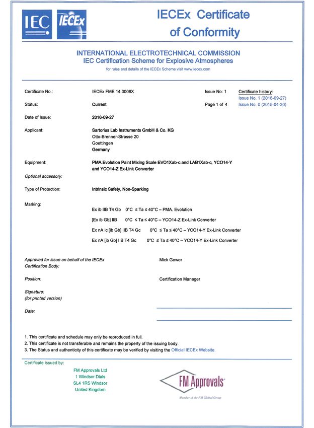
English
Contents 1.2.1 Warnings
1 About This Document . . . . . . . . . . . . . . . . . . . . . . . . . . . . . . 3 WARNING
1.1 Scope . . . . . . . . . . . . . . . . . . . . . . . . . . . . . . . . . . . . . . . . 3 Denotes a danger with risk that death or severe injury may
1.2 Symbols Used . . . . . . . . . . . . . . . . . . . . . . . . . . . . . . . . . 3 result if it is not avoided.
2 Safety . . . . . . . . . . . . . . . . . . . . . . . . . . . . . . . . . . . . . . . . . . . . 3 CAUTION
2.1 Intended Use . . . . . . . . . . . . . . . . . . . . . . . . . . . . . . . . . . 3 Denotes a danger with risk that moderate or minor injury may
2.2 Explosion Protection . . . . . . . . . . . . . . . . . . . . . . . . . . . . 4 result if it is not avoided.
2.3 Personnel Qualification . . . . . . . . . . . . . . . . . . . . . . . . . 4
2.4 Significance of these Instructions . . . . . . . . . . . . . . . . . 5 NOTICE
2.5 Proper Working Order of the Device . . . . . . . . . . . . . . 5 Denotes a danger that can result in property damage if the
2.6 Work on the Electrical Equipment of the Device . . . . 5 risk is not avoided.
2.7 Personal Protective Equipment . . . . . . . . . . . . . . . . . . . 5
2.8 Safety Instructions Concerning Operation 1.2.2 Other Symbols
of the Device . . . . . . . . . . . . . . . . . . . . . . . . . . . . . . . . . . 5
3 Installation . . . . . . . . . . . . . . . . . . . . . . . . . . . . . . . . . . . . . . . 5 t Required action: Describes actions which must be
3.1 Scope of Delivery . . . . . . . . . . . . . . . . . . . . . . . . . . . . . . 5 carried out.
3.2 Unpacking . . . . . . . . . . . . . . . . . . . . . . . . . . . . . . . . . . . . 5 y Result: Describes the result of the activities
3.3 Selecting a Setup Location . . . . . . . . . . . . . . . . . . . . . . 5 carried out.
3.4 Installing the Scale . . . . . . . . . . . . . . . . . . . . . . . . . . . . . 6
[ ] Text inside brackets refers to control and display
3.5 Connecting the Grounding Cable . . . . . . . . . . . . . . . . . 6
elements.
3.6 Establishing the Power Supply . . . . . . . . . . . . . . . . . . . 7
3.7 Anti-theft Locking Device . . . . . . . . . . . . . . . . . . . . . . . 8 This symbol provides information for the sale of
3.8 Leveling . . . . . . . . . . . . . . . . . . . . . . . . . . . . . . . . . . . . . . 8 scales verified for use in legal metrology.
3.9 Warm-up Time . . . . . . . . . . . . . . . . . . . . . . . . . . . . . . . . 8 In the following, the term “verified” is used to
mean “verified for use in legal metrology” or
4 Cleaning and Maintenance . . . . . . . . . . . . . . . . . . . . . . . . . 9 “conformity-assessed.”
4.1 Cleaning . . . . . . . . . . . . . . . . . . . . . . . . . . . . . . . . . . . . . . 9
4.2 Servicing . . . . . . . . . . . . . . . . . . . . . . . . . . . . . . . . . . . . . 9
5 Disposal . . . . . . . . . . . . . . . . . . . . . . . . . . . . . . . . . . . . . . . . . . 9 Figures on the Operating Display
5.1 Information on Decontamination . . . . . . . . . . . . . . . . . 9 The figures in these instructions are based on “standard”
scales. On verified scales, some displays and reports may
6 Accessories . . . . . . . . . . . . . . . . . . . . . . . . . . . . . . . . . . . . . . 10
deviate slightly from the figures. Where this is significant
7 Serial Number Coding . . . . . . . . . . . . . . . . . . . . . . . . . . . . 10 for operation, the differences will be explained in the text.
8 Technical Data . . . . . . . . . . . . . . . . . . . . . . . . . . . . . . . . . . . 11
8.1 General Data . . . . . . . . . . . . . . . . . . . . . . . . . . . . . . . . . 11
8.2 Model-specific Data . . . . . . . . . . . . . . . . . . . . . . . . . . . 12 2 Safety
8.3 Verified Models with EC Type Approval Certificate:
Model-specific Technical Data . . . . . . . . . . . . . . . . . . 12
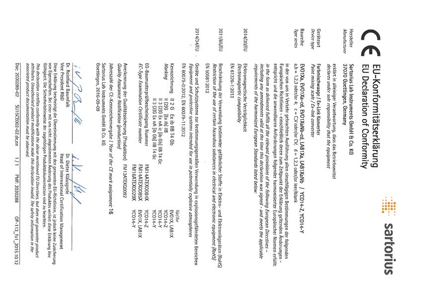
9 EU Declaration of Conformity . . . . . . . . . . . . . . . . . . . . . 12 2.1 Intended Use
This scale is only intended for mixing colors and paints.
Appropriate containers must be used for loading each type
1 About This Document of material.
The scale can be operated via the display as a stand-alone
device or using application software (e.g., a paint-mixing
1.1 Scope program from a paint manufacturer) installed on a connected
PC. The PC is connected to the ex-link converter via a USB
This operating manual applies to paint-mixing scale models: cable. Follow and observe the explosion protection
instructions in Chapter 2.2, page 4.
−− EVO1X
−− LAB1X These instructions are part of the device. The device is
intended exclusively for use in accordance with these
1.2 Symbols Used instructions.
The term “device” used in these instructions always refers to
the combined unit of scale, AC adapter and ex-link converter.
EVO1X | LAB1X Installation Instructions 3
Any further use beyond this is considered improper. If the         2.3      Personnel Qualification
device is not used properly: The protective systems of the
device may be impaired. This can lead to unforeseeable             These instructions are addressed to the target groups below
personal injury or property damage.                                mentioned. All persons working on the device must possess
In the event of use in systems and under ambient conditions        the stated knowledge and authorizations.
with higher safety requirements, you must observe the              If no qualifications are indicated for the actions described in
requirements and provisions applicable in your country.            these instructions: The actions described are addressed to the
                                                                   “User” target group.
Operating Conditions for the Device                                If individual actions must be carried out by other target
The device may only be used indoors.                               groups or by Sartorius Service personnel: The qualification
The device may only be used with the equipment and under           required will be indicated in the description of the action.
the operating conditions described in the Technical Data           Target group Knowledge/responsibilities
section of these instructions.
                                                                   User            The user is familiar with the operation of the
You may not modify the device or make any technical                                device and the associated work processes.
changes on your own. Any retrofitting or technical changes                         The user understands the hazards which may
to the device are only permitted with prior written permission                     arise when working with the device and can
by Sartorius.                                                                      avoid these hazards.
Do not expose the device or accessories supplied by Sartorius                      The user has been trained in the operation of
to extreme temperatures, aggressive chemical vapors,                               the device. Training takes place within the
moisture, shock, vibrations or strong electromagnetic fields.                      scope of startup and is carried out by the
Observe the conditions of operation described in the Technical                     operating engineer/laboratory manager or
Data section.                                                                      the operator of the device.
The casing on all connection cables between the devices as         Operating       The operating engineer/laboratory manager
well as on the wires inside the device housing are made of         engineer/       makes decisions about the use and
PVC. Chemicals that corrode this material must be kept away        laboratory      configuration of the device.
from these cables.                                                 manager         The operating engineer/laboratory manager
                                                                                   has been trained in the operation of the
                                                                                   device. Training takes place within the scope
2.2     Explosion Protection                                                       of startup and is carried out by Sartorius
                                                                                   Service or the operator.
Use within the scope of validity of the European ATEX              Electrician     A qualified electrician has the specialized
Directive:                                                                         training, knowledge, and experience as well
−− In accordance with Directive 2014/34/EU, the model in the                       as familiarity with applicable standards and
   EVO1X | LAB1X series is a category 2 device, suitable for                       regulations to evaluate the assigned work
   use in Zone 1 potentially explosive areas.                                      and identify possible hazards.
−− The ex-link converter YCO14-Z is only suitable for              Operator        The operator of the device is responsible for
   installation as an associated electrical apparatus outside                      compliance with safety requirements and
   of the potentially explosive area.                                              workplace safety regulations.
−− The ex-link converter YCO14-Y is an associated electrical                       The operator must ensure that all persons
   apparatus that can be used in Zone 2.                                           who work on the device have access to the
−− Refer to the EC Type Examination Certificates from                              relevant information and have been
   Page 53 for the device ID codes. Please observe the                             instructed in work on the device.
   safety instructions in drawing 2023040 from Page 53.

Use in Canada and the USA:
The intrinsically safe scales in the EVO1X | LAB1X model series
are suitable for use in Class I, Division 1 and Class I, Zone 1.
The ex-link converter YCO14-Y can be used in Class I, Division
2 and Class I, Zone 2.
Please observe Certificates of Conformity FM16US0226X
and FM16CA0124X as well as Control Drawing 2021459 from
Page 53.

Use in Australia/New Zealand:
Please observe IECEx Certificate of Conformity IECEx FME
14.0008X and Safety Instructions 2023040 from Page 53.

4       EVO1X | LAB1X Installation Instructions
English

2.4     Significance of these Instructions                         −− The surface of the operating display should not be touched
                                                                      with pointed, sharp, hard, or rough objects. You should
Failure to follow the instructions in this manual can have            only use the touch pen provided or your fingertips. Do not
serious consequences, e.g., exposure of individuals to                use parts of clothing (e.g., sleeves) or sponges for cleaning
electrical, mechanical, or chemical hazards.                          because these can scratch the surface (e.g., due to rivets or
ttBefore working with the device: Read the instructions               buttons in the sleeve or sand in the sponge).
  carefully and completely.                                        −− Avoid generating static electricity on the glass panel of
ttIf these instructions are lost: Request a replacement or            the operating display and plastic casing.
  download the latest version from the Sartorius website                          Danger of Damage to the Scale!
  (www.sartorius.com).                                                            Never close a paint can using a hammer while
ttThe information contained in these instructions must be                         it is still on the weighing pan.
  available to all individuals working on the device.                             When closing, place the paint can on a firm,
                                                                                  stable surface.
2.5     Proper Working Order of the Device
A damaged device can cause malfunctions or lead to hard-to-
detect hazards.
ttOnly operate the device when it is safe and in perfect
                                                                   3       Installation
  working order.
ttImmediately disconnect the damaged device from the
                                                                   3.1     Scope of Delivery
  power.
ttHave any malfunctions or damage repaired immediately
  by the Sartorius Service.                                        Model                              PMA.Evolution       PMA.HD
                                                                   Large weighing pan: d 233 mm       x                   –
2.6     Work on the Electrical Equipment of the                    Small weighing pan: d 180 mm       –                   x
        Device                                                     USB cable                          x                   x
                                                                   Ex-link converter                  x                   x
Work on and modifications to the electrical equipment of the
device may only be carried out by Sartorius Service personnel.     Potential equalization cable       x                   x
The device may only be opened by Sartorius Service personnel.      Link cable from converter to
                                                                                                      x                   x
                                                                   scale
          Seal on Scales Verified for Use in Legal
                                                                   Installation instructions          x                   x
          Metrology
          Legislation requires that a seal be affixed to
          verified scales. On Sartorius devices, this seal takes
          the form of a sticker with the “Sartorius” logo.         3.2     Unpacking
          If the seal is removed, the validity of verification
          will become void and you must have your scale            Procedure
          re-verified. The verification supplied here is for
                                                                   ttOpen the packaging, making sure to remove all parts
          verified weighing instruments for use in the EEA.
                                                                      carefully.
          Please keep it in a safe place.
                                                                   ttAfter unpacking the device, check it immediately for any
                                                                      external damage.
                                                                   ttIf the device is stored temporarily: Store the device
2.7     Personal Protective Equipment                                 according to the ambient conditions (ambient conditions
Personal protective equipment to protect against risks arising        see Chapter “8.1 General Data”, page 11).
from the material being processed.                                 ttSave the box and all parts of the packaging for any future
                                                                      transport. All cables should be unplugged when
ttWhen the workplace or the process, in which the device              transporting.
  is used, requires personal protective equipment: Wear
  personal protective equipment.                                   3.3     Selecting a Setup Location
                                                                   Select the right setup location:
2.8     Safety Instructions Concerning Operation                   −− Set up the device on a stable, even surface that is not
        of the Device                                                  exposed to vibrations.
                                                                   −− Maintain free access to the device at all times.
−− Take care that the glass panel of the operating display is      −− The devices must be handled carefully according to the
   not damaged (e.g., by falling objects, impact, or extreme           IP protection rating. The environment must be suitably
   pressure). If the glass panel is damaged, disconnect the            secured.
   device from the power supply immediately.

                                                                                      EVO1X | LAB1X Installation Instructions      5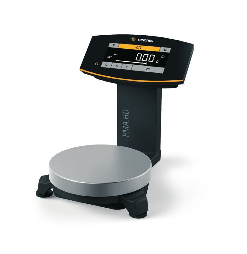
−− In the event of use in systems and under ambient                                         ttConnect the link cable to the
   conditions with higher safety requirements, you must                                       ex-link converter.
   observe the requirements and provisions applicable in
   your country.

Choose a location that is not subject to the following negative
influences:
−− Heat (heater or direct sunlight)
−− Drafts from open windows, AC systems, and doors
−− Extreme vibrations during weighing
                                                                  3.5     Connecting the Grounding Cable
−− Heavy traffic areas (personnel)
−− Extremely high humidity                                        Required qualification: Electrician
−− Electromagnetic fields
−− Extremely dry air                                              This explosion-protected system should be set up according
                                                                  to commonly accepted technical standards. The applicable
Acclimatization                                                   national electrical code and safety regulations for your
                                                                  particular country must be observed.
Condensation from humidity can form on the surfaces of a
                                                                  Before commissioning the scale, a check must be carried out
cold device when it is brought into a warm area. You should
                                                                  by or under the supervision of a qualified electrician to ensure
therefore let a device that has been disconnected from its
                                                                  that the system is in good working order.
power source acclimatize for approximately 2 hours before
reconnecting it to the supply voltage.                            Check whether or not the competent authorities (e.g.,
                                                                  industrial supervisory board) need to be informed. It is also
3.4     Installing the Scale                                      necessary to carry out inspections of the system during
                                                                  operation.
NOTICE                                                            Inspection intervals should be such that any significant
The device must be disconnected from the power supply for         defects that may occur can be identified in good time.
all assembly work.                                                Inspections should be carried out at least once every three
                                                                  years. The applicable requirements and guidelines should
                                                                  also be observed during operation.
3.4.1   Place the weighing pan on the scale                       The system should only be operated for the first time when
                                                                  it is certain that the area is not potentially explosive.
                           ttPlace the weighing pan onto the
                                                                  If deviations are evident during startup due to transport
                             scale from above.
                                                                  damage (e.g., no display, no backlighting), disconnect the
                                                                  scale from the power supply and contact the Sartorius Service
                                                                  Center.
                                                                  Installation must be carried out properly by a trained
                                                                  electrician and according to commonly accepted technical
                                                                  standards.
                                                                                             Connect the scale to the equipo-
3.4.2   Connecting the Scale                                                                 tential bonding conductor using
                                                                                             an equipotential bonding cable
                           ttInsert the link cable plug into                                 with a gauge of at least 4 mm2.
                             the RJ-45 socket on the back of                                ttConnect the cable lug of the
                             the display.                                                     equipotential bonding cable to
                                                                                              the grounding terminal of the
                                                                                              scale.
                                                                                            ttConnect the equipotential
                           ttLay the link cable (blue) through                                bonding cable to the custom-
                             the cable holders on the back of                                 er-supplied equipotential
                             the scale.                                                       bonding conductor.

6       EVO1X | LAB1X Installation Instructions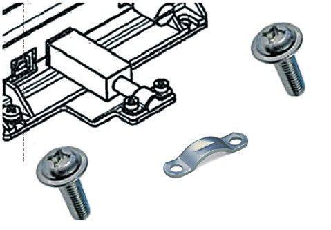
English

                           Connect the ex-link converter to      Bag          Region/country
                           the equipotential bonding conduc-     YEPS01-PS6   −−     Argentina (AR)
                           tor using another equipotential                    −−     Brazil (BR)
                           bonding cable with a gauge of at                   −−     Australia (AU)
                           least 4 mm2.                                       −−     South Africa (ZA)
                           ttConnect the cable lug of the
                               equipotential bonding cable to    YEPS01-PS7   −− China (CN)
                               the grounding terminal of the                  −− India (IN)
                               ex-link converter.                             −− Korea (KR)
                           ttConnect the equipotential
                               bonding cable to the custom-
                               er-supplied equipotential                                  ttInsert the power plug adapter
                               bonding conductor.                                           into the power supply. The
                                                                                            grooved button must be facing
                                                                                            upwards.
3.6      Establishing the Power Supply
                                                                                          ttPush the power plug adapter as
Required qualification: Electrician                                                         far as you can until it clicks into
The scale is connected to the power supply via a PC/                                        place.
notebook or using the optional AC adapter YEPS01-USB                                      ttCheck whether the power plug
(see Chapter “6 Accessories”, page 10), which is supplied with                              adapter is securely locked in
mains adapters for use in various countries.                                                place by pulling it gently.
                                                                                          yyIf the power plug adapter does
                                                                                            not move, it is locked in place.
NOTICE
−− Ensure that the voltage rating printed on the AC adapter
   is identical to your local mains voltage (connection data                              Removing/Replacing the Mains
   see Chapter “8.1 General Data,” page 11).                                              Adapter
−− If the stated supply voltage or the plug design of the AC                              ttPress the grooved button from
   adapter does not comply with your country's standard,                                     above and pull back on the
   please inform your nearest Sartorius representative.                                      mains adapter.
                                                                                          ttPush the power plug adapter
                                                                                             out of the power supply and
Power supply via the AC adapter is only required:
                                                                                             remove it.
−− When no PC or notebook is available.
−− In exceptional cases, when the output voltage of the
   USB interface of the PC or notebook is not sufficient.
                                                                                          Connecting a PC/Notebook
AC adapter assembly is described in the following.                                        ttInsert a USB cable (1) into
                                                                                             the right-hand socket on the
                                                                                             ex-link converter and connect
3.6.1    Installing AC Adapter
                                                                                             the cable to a PC or notebook.
tt      WARNING Lethal electric shock and equipment                           1              If the ex-link converter
     damage due to incorrect power plug adapter! Only use                                    YCO14-Y is being used and
     the country-specific power plug adapter. Never plug                                     installed in Zone 2 or Division 2
     the power plug adapter into the socket when it is                                       potentially explosive areas and
     disconnected from the AC adapter.                                                       the USB cable (1) does
                                                                                             not have an intrinsically safe
ttSelect the correct mains adapter for your mains power
                                                                                             electrical circuit, the cable
  supply. The mains adapter must be suitable for use with
                                                                                             must be secured against
  the wall outlet at the installation site.
                                                                                             disconnection. Refer to the
                                                                                             Control Drawing 2021459 and
Mains adapter sets
                                                                                             Safety Instructions 2023040
Bag                Region/country                                                            from Page 53 as well as the
                                                                                             following illustrations.
YEPS01-PS1         −− USA and Japan (US+JP)
                   −− Europe (EU)
                   −− United Kingdom (GB)

                                                                                  EVO1X | LAB1X Installation Instructions        7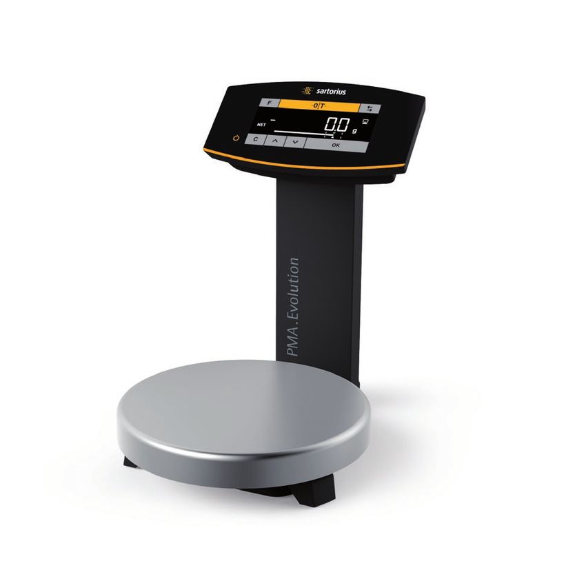
ttFasten the      3.7             Anti-theft Locking Device
                                                   strain relief
                                                   YSR01 to the                                    ttIf required, secure the scale at
                             2                     converter (1)                                     the back.
           2                                       using the two
                                                   screws (2).

                                             1

                                                                   3.8             Leveling
                                                 ttAttach the      Leveling for PMA.HD and Verified Models
                                                   USB cable to
                                                                   Leveling the scale compensates for slant or unevenness at the
                                                   the strain
                                     2                             place of installation. The scale must be perfectly horizontal to
                                                   relief (1)
                                                                   ensure consistent, reproducible weighing results.
                                 3                 using the
                                                   clamp (3)       The scale needs to be re-leveled and then adjusted if
                                                   and the two     necessary each time its setup location is changed.
                                         1
                                                   screws (4).
               2                                                                                   ttTurn the two leveling feet as
                                                                                                      shown in the illustration until
                                                                         12*                          the air bubble is centered within
                                                 ttUse the          9*                                the circle of the level indicator.
                                                   protective                                      −− Air bubble at “12 o'clock:” Turn
                                                                          6*                          both feet clockwise.
                         5                         cap (6) to
                                                   seal up the                                     −− Air bubble at “3 o'clock:” Turn
                                                   left-hand                                          the left foot clockwise and the
                                                                     * o'clock                        right foot counterclockwise.
                                                   USB port (5).
                                                                                                   −− Air bubble at “6 o'clock:” Turn
                                                                                                      both feet counterclockwise.
                         6
                                                                                                   −− Air bubble at “9 o'clock:” Turn
                                                                                                      the left foot counterclockwise
                                                                                                      and the right foot clockwise.

                             Connecting the AC Adapter
                             (Optional); not for YCO14-Y           3.9             Warm-up Time
                             when Installed in Zone 2 or
                             Division 2 Potentially Explosive                       Using a Scale Verified for Use in Legal
                             Areas                                                  Metrology:
    2                        ttInsert an additional USB cable                       Ensure that there is a warm-up time of at least
                                (2) into the ex-link converter.                     24 hours after initial connection to the power
                                                                                    supply.

                             ttInsert the USB cable into the                   0            To ensure accurate results are delivered,
                               YEPS01-USB AC adapter.                                       the scale must warm up for at least
                             ttPlug the AC adapter into a wall                              30 minutes after initial connection to
                               outlet (supply voltage).                                     the power supply.
                                                                                            Only then will the device have reached the
                                                                                            required operating temperature.
                                                                           30

8       EVO1X | LAB1X Installation Instructions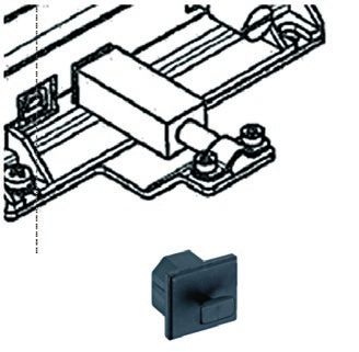
English

4        Cleaning and                                          5       Disposal
         Maintenance
                                                               5.1     Information on Decontamination

4.1      Cleaning                                              According to the EU directives [European directive on
                                                               hazardous substances], the owners of devices that come
Before cleaning the AC adapter, ex-link converter, or the      into contact with hazardous substances are responsible for
scale: Disconnect all devices from the power supply.           properly disposing of these devices and for declaring such
                                                               devices when transporting them.
  WARNING Electrical Hazard from Voltage or
Current                                                            WARNING
Disconnect the AC adapter (if connected) from the mains.       Risk of injury due to contaminated devices!
Unplug any connected data cables from the ex-link converter.
Never open the scale or the AC adapter. The parts contained    Devices contaminated with hazardous materials (NBC contam-
in these cannot be cleaned, repaired or replaced by the        ination) will not be accepted for repair or disposal.
operator.

NOTICE                                                         5.1.1   Information on Disposal
Do not clean the following parts with acetone or aggressive    The device and its accessories do not belong in your regular
cleaning agents:                                               household waste, since they are made of high-grade materials
−− Mains socket                                                which can be recycled and reused. All parts must be disposed
−− Data interface                                              of properly by disposal facilities.
−− Labels, and all other plastic parts
                                                               The packaging is made of environmentally friendly materials
                                                               that can be used as secondary raw materials.
Procedure
ttDisconnect the device from the power supply.
                                                               5.1.2   Disposal
ttNOTICE Make sure that no liquid or dust gets into the
   scale or the AC adapter.
ttNOTICE Corrosion or damage to the device due to              Requirements
   unsuitable cleaning agents!                                 The device has been decontaminated.
   ttDo not use corrosive, chloride-containing and
       aggressive cleaning agents.                             Procedure
   ttDo not use cleaning agents that contain abrasive          ttDispose of the device. Follow the disposal instructions on
       ingredients, e.g. scouring agents, steel wool.             our website (www.sartorius.com).
   ttOnly use soft brushes and cloths for cleaning.            ttDispose of the packaging in accordance with local
   ttDo not use solvent-based cleaning agents.                    government regulations.
Cleaning the Control Panel
ttBefore cleaning the control panel: Turn off the device as
   touching the screen could trigger unwanted inputs.

Cleaning the Device Housing
ttWipe off the housing with a slightly damp cloth. For more
   severe contamination, use a mild soap solution.
ttWipe the device with a soft cloth.

4.2      Servicing
To ensure the continued accuracy of your scale, we
recommend scheduling regular servicing at least once a year.
Sartorius Service offers different service contracts with
maintenance intervals that are tailored to your needs.
A calibration certificate should always be issued as part
of every maintenance session. Safety inspections of the
AC adapter and its connections must be performed at
appropriate intervals by a qualified electrician (e.g. every
2 years).

                                                                                  EVO1X | LAB1X Installation Instructions     9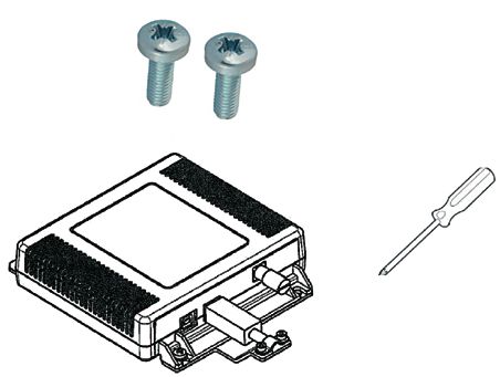
6 Accessories 7 Serial Number Coding
Accessories Order Number Sartorius Lab Instruments GmbH & Co. KG
Power supply (5.2 V/1.4 A) YEPS01-USB 37070 Goettingen, Germany Made in Germany
USB cable, 5 m YCC01-0040M5 产品型号:
Mains adapter set for YEPS01-USB YEPS01-PS1
产品名称:卓逸PMA
−− USA and Japan (US+JP)
−− Europe (EU) 0°C Ta +40°C II 2GEx ib IIB T4 Gb
−− United Kingdom (GB) FM 14ATEX0085X
IECEx FME 14.0008X
Mains adapter set for YEPS01-USB YEPS01-PS6 2809 PCEC CE16.2058X
−− Argentina (AR) CA: Ex ia IS CL I, Div 1, GP C,D T4
−− Brazil (BR) Zone 1, Ex ib IIB T4
−− Australia (AU) USA: IS CL I, Div 1, GP C,D T4
−− South Africa (ZA) CL I, Zone 1, AEx ib IIB T4
Mains adapter set for YEPS01-USB YEPS01-PS7 For installation and maintenance see control drawing
−− China (CN) 2021459. Pour installation et maintenance voir le No
−− India (IN) 2021459 du diagramme de contrôle.
−− Korea (KR) 安装和维护请参见安全说明 2021459。1000011682
Ex-link converter YCO14-Y
The manufacture date of this device is encoded in the serial
Ex-link converter YCO14-Z number. The format is as follows:
Link cable
YMM x x x x x
from converter to scale, 10 m YCC01-0052M10
Y Year
from converter to scale, 20 m YCC01-0052M20 3 2014-2020
from converter to scale, 30 m YCC01-0052M30 4 2021-2027
Strain relief YSR01 5 2028-2034, etc.
Equipotential bonding cable, 2 m YCC01-X046M2
In-use dust cover The Y column indicates the year group, which covers a period
of 7 years. Within each year group, the months (M M) are
for control panel, pack of 10 YDC03PMA10 counted up from 13.
for stand, PMA.Evolution, pack of 10 YDC03PMA-CO10
Year: 2015 2016 2017 2018 2019 ...
for weighing pan, PMA.Evolution, YDC03P- MM: 25-36 37-48 49-60 61-72 73-84 ...
pack of 10 MA-WP10
Calibration weights Example:
for PMA.Evolution: 328xxxxx (April 2015). “xxxxx” is a consecutive number. Every
−− 5 kg, accuracy class F2 YCW654-AC-00 month it starts with 1 and increases consecutively.
−− 2 kg, accuracy class F2 YCW624-AC-00
−− 1 kg, accuracy class F2 YCW614-AC-00
for PMA.HD:
−− 2 kg, accuracy class F1 YCW623-AC-00
−− 1 kg, accuracy class F1 YCW613-AC-00
10 EVO1X | LAB1X Installation InstructionsEnglish
8 Technical Data
8.1 General Data
Specification Unit Value
Scale
Supply voltage Only via USB interface or Sartorius AC adapter YEPS01-USB
Input voltage VDC +4.5 to 5.0
Power consumption W 2.0 (typically)
Further data IP40 in accordance with EN 60529/IEC 60529
Ambient conditions
The technical data apply under the following ambient conditions:
Environment For indoor use only.
Ambient temperature* °C +10 to +30
Operational capability °C Guaranteed between +5 and +40.
Storage and shipping °C -10 to +60
Relative humidity % Up to 80% for temperatures up to 30°C non-condensing, decreasing
linearly up to 50% relative humidity at 40°C
Ex-link converter interface connection USB, type B
Electromagnetic compatibility In accordance with EN 61326-1/IEC 61326-1 Electrical equipment for
measurement, control and laboratory use – EMC requirements – Part 1:
General Requirements.
Interference resistance Basic requirements
Transient emissions Class B
Suitable for use in residential areas and areas that are connected to a
low voltage network that also supplies residential buildings.
Verified scales in accordance with EU requirements comply with the
requirements of Council Directive 2014/31/EC with EN 45501:2015 and
OIML R76:2006.
* For verified scales in accordance with EU requirements, refer to the
information on the scale.
** For verified scales in accordance with EU requirements, the legal
regulations apply.
Available application programs Recalculation, factor calculation, formula
Power supply YEPS01-USB
USB power plug Type FSP007-P01P (manufacturer’s designation)
Primary 100–240 V~, ±10%, 50–60 Hz, ±5%, < 0.2 A
Secondary 5.2 VDC, ± 5%, 1.4 A (max.)
Further data Protection class II
IP40 in accordance with EN 60529/IEC 60529
Ex-link converter YCO14-Y | YCO14-Z
Further data IP40 in accordance with EN 60529/IEC 60529
EVO1X | LAB1X Installation Instructions 118.2 Model-specific Data
Model
Specification Unit Value Value
PMA.Evolution PMA.HD
EVO1X LAB1X
Weighing capacity g 7500 / 999.95 2200
Readability g 0.1 / 0.05 0.01 / 0.1
Tare range (subtractive) g -7500 -2200
External adjustment weight / kg 1, 2, 5 / 1, 2 /
accuracy class F2 or better F1 or better
Diameter of weighing pan mm 233 180
Net weight kg 2.4 2.3
8.3 Verified Models with EC Type Approval Certificate: Model-specific Technical Data
Specification Unit Value
Model PMA.Evolution, EVO1X
Accuracy class II
Type PMA-EV
Weighing capacity max. g 7500
Scale interval d g 0.1
Verification scale interval e g 1
Temperature range +10°C to +30°C
Tare equalization range (subtractive) < 100% from max. weighing capacity
Specification Unit Value
Model PMA.HD, LAB1X
Accuracy class III
Type PMA-HD
Weighing capacity max. g 2200
Scale interval d g 1
Verification scale interval e g 1
Temperature range +10°C to +40°C
Tare equalization range (subtractive) < 100% from max. weighing capacity
9 EU Declaration of Conformity
The attached Declaration of Conformity hereby confirms compliance of the device with the directives cited.
The declaration of conformity supplied here is for verified balances for use in the EEA. Please keep it in a safe place.
12 EVO1X | LAB1X Installation InstructionsDeutsch
Inhalt 1.2.1 Warnungen
1 Über dieses Dokument . . . . . . . . . . . . . . . . . . . . . . . . . . . . 13 WARNUNG
1.1 Gültigkeit . . . . . . . . . . . . . . . . . . . . . . . . . . . . . . . . . . . . 13 Kennzeichnet eine Gefährdung, die Tod oder schwere Körper-
1.2 Darstellungsmittel . . . . . . . . . . . . . . . . . . . . . . . . . . . . 13 verletzung zur Folge haben kann, wenn sie nicht vermieden
wird.
2 Sicherheit . . . . . . . . . . . . . . . . . . . . . . . . . . . . . . . . . . . . . . . 13
2.1 Bestimmungsgemäße Verwendung . . . . . . . . . . . . . . . 13 VORSICHT
2.2 Explosionsschutz . . . . . . . . . . . . . . . . . . . . . . . . . . . . . . 14 Kennzeichnet eine Gefährdung, die eine mittelschwere oder
2.3 Personalqualifikation . . . . . . . . . . . . . . . . . . . . . . . . . . 14 leichte Körperverletzung zur Folge haben kann, wenn sie nicht
2.4 Bedeutung dieser Anleitung . . . . . . . . . . . . . . . . . . . . 15 vermieden wird.
2.5 Einwandfreiheit des Geräts . . . . . . . . . . . . . . . . . . . . . 15
2.6 Arbeiten an der elektrischen Ausrüstung ACHTUNG
des Geräts . . . . . . . . . . . . . . . . . . . . . . . . . . . . . . . . . . . 15 Kennzeichnet eine Gefährdung, die Sachschäden zur Folge
2.7 Persönliche Schutzausrüstung . . . . . . . . . . . . . . . . . . . 15 haben kann, wenn sie nicht vermieden wird.
2.8 Sicherheitshinweise zur Bedienung des Gerätes . . . . 15
3 Installation . . . . . . . . . . . . . . . . . . . . . . . . . . . . . . . . . . . . . . 15 1.2.2 Weitere Darstellungsmittel
3.1 Lieferumfang . . . . . . . . . . . . . . . . . . . . . . . . . . . . . . . . . 15
3.2 Auspacken . . . . . . . . . . . . . . . . . . . . . . . . . . . . . . . . . . . 15 t Handlungsanweisung: Beschreibt Tätigkeiten, die
3.3 Aufstellort wählen . . . . . . . . . . . . . . . . . . . . . . . . . . . . 15 ausgeführt werden müssen.
3.4 Waage montieren . . . . . . . . . . . . . . . . . . . . . . . . . . . . . 16 y Ergebnis: Beschreibt das Ergebnis der ausgeführ-
3.5 Erdung anschließen . . . . . . . . . . . . . . . . . . . . . . . . . . . 16 ten Tätigkeiten.
3.6 Spannungsversorgung herstellen . . . . . . . . . . . . . . . . 17
[ ] Verweis auf Bedien- und Anzeigeelemente
3.7 Diebstahlsicherung . . . . . . . . . . . . . . . . . . . . . . . . . . . . 18
3.8 Nivellieren . . . . . . . . . . . . . . . . . . . . . . . . . . . . . . . . . . . 18 Dieses Symbol gibt einen Hinweis für den eich-
3.9 Anwärmzeit . . . . . . . . . . . . . . . . . . . . . . . . . . . . . . . . . . 18 pflichtigen Verkehr für konformitätsbewertete
(geeichte) Waagen.
4 Reinigung und Wartung . . . . . . . . . . . . . . . . . . . . . . . . . . . 19 Im weiteren Text steht der Begriff ‚geeicht‘ für
4.1 Reinigen . . . . . . . . . . . . . . . . . . . . . . . . . . . . . . . . . . . . . 19 den Fachausdruck konformitätsbewertet.
4.2 Warten . . . . . . . . . . . . . . . . . . . . . . . . . . . . . . . . . . . . . . 19
5 Entsorgung . . . . . . . . . . . . . . . . . . . . . . . . . . . . . . . . . . . . . . 19
5.1 Hinweise zur Dekontamination . . . . . . . . . . . . . . . . . . 19 Abbildungen der Bedienanzeige
Die Abbildungen in dieser Anleitung basieren auf „Stan-
6 Zubehör . . . . . . . . . . . . . . . . . . . . . . . . . . . . . . . . . . . . . . . . . 20
dard“-Waagen. Bei den geeichten Waagen können einige
7 Codierung der Seriennummer . . . . . . . . . . . . . . . . . . . . . . 20 Anzeigedarstellungen und Protokolle von den Abbildungen
etwas abweichen. Wo dies für den Betrieb von Bedeutung ist,
8 Technische Daten . . . . . . . . . . . . . . . . . . . . . . . . . . . . . . . . . 21
werden die Unterschiede im Text erläutert.
8.1 Allgemeine Daten . . . . . . . . . . . . . . . . . . . . . . . . . . . . . 21
8.2 Modellspezifische Daten . . . . . . . . . . . . . . . . . . . . . . . 22
8.3 Geeichte Modelle mit EG-Bauartzulassung:
Modellspezifische technische Daten . . . . . . . . . . . . . . 22 2 Sicherheit
9 EU-Konformitätserklärung . . . . . . . . . . . . . . . . . . . . . . . . 22
2.1 Bestimmungsgemäße Verwendung
1 Über dieses Dokument Diese Waage ist nur bestimmt für das Mischen von Farben und
Lacken. Zur Aufnahme der Materialien müssen geeignete
Gefäße verwendet werden.
1.1 Gültigkeit Die Waage darf sowohl über das Display im Stand Alone
Betrieb, als auch mit Hilfe einer auf dem PC installierten
Diese Betriebsanleitung gilt für Farbmischwaagen der Applikationssoftware (z. B. eine Farbmischapplikation des
Modellreihen: Lackherstellers) gesteuert werden. Der PC wird dabei über ein
USB Kabel mit dem Ex-Link Konverter verbunden. Die Anga-
−− EVO1X
ben zum Explosionsschutz im Kapitel 2.2, Seite 14 sind zu
−− LAB1X
beachten.
1.2 Darstellungsmittel Die Anleitung ist Teil des Geräts. Das Gerät ist ausschließlich
für den Einsatz gemäß dieser Anleitung bestimmt.
Der in der Anleitung verwendete Begriff Gerät bezeichnet immer
die Kombination Waage, Netzgerät und Ex-Link Konverter.
Installationsanleitung EVO1X | LAB1X 13Jede weitere Verwendung gilt als nicht bestimmungsgemäß. Die Certificates of Conformity FM16US0226X und
Wenn das Gerät nicht bestimmungsgemäß eingesetzt wird: FM16CA0124X sowie die Control Drawing 2021459 ab
Die Schutzmaßnahmen des Geräts können beeinträchtigt Seite 53 sind zu beachten.
werden. Dies kann zu unabsehbaren Personenschäden oder
Sachschäden führen. Verwendung in Australien/Neuseeland:
Bei Verwendung in Anlagen und Umgebungsbedingungen mit Das IECEx Certificate of Conformity IECEx FME 14.0008X
erhöhten Sicherheitsanforderungen die Auflagen und Bestim- sowie die Safety Instructions 2023040 ab Seite 53 sind zu
mungen Ihres Landes beachten. beachten.
Einsatzbedingungen für das Gerät
2.3 Personalqualifikation
Das Gerät nur in Gebäuden verwenden.
Das Gerät nur mit den Ausstattungen und unter Betriebsbe- Diese Anleitung richtet sich an die unten genannten Zielgrup-
dingungen einsetzen wie sie in den technischen Daten dieser pen. Alle Personen, die am Gerät arbeiten, müssen über die
Anleitung beschrieben sind. genannten Kenntnisse und Zuständigkeiten verfügen.
Das Gerät nicht eigenmächtig umbauen oder technisch Wenn bei den beschriebenen Tätigkeiten in dieser Anleitung
verändern. Umbaumaßnahmen und technische Änderungen keine Qualifikation angegeben ist: Die beschriebenen Tätig-
am Gerät sind nur nach einer vorherigen schriftlichen keiten richten sich an die Zielgruppe „Bediener“.
Genehmigung durch Sartorius gestattet. Wenn einzelne Tätigkeiten durch andere Zielgruppen oder den
Das Gerät sowie das von Sartorius gelieferte Zubehör nicht Sartorius Service ausgeführt werden müssen: Die benötigte
extremen Temperaturen, aggressiven chemischen Dämpfen, Qualifikation ist bei der Beschreibung der Tätigkeit
Feuchtigkeit, Stößen, Vibrationen oder starken elektromagne- angegeben.
tischen Feldern aussetzen. Einsatzbedingungen gemäß den Zielgruppe Kenntnisse und Zuständigkeiten
Technischen Daten einhalten!
Bediener Der Bediener ist mit dem Betrieb des Geräts und
Die Verbindungskabel zwischen den Geräten sowie die
den damit verbundenen Arbeitsprozessen ver-
Ummantelung der Litzen der inneren Verdrahtungen bestehen
traut. Er kennt die Gefahren, die bei Arbeiten
aus PVC-Materialien. Chemikalien, die diese Materialien
mit dem Gerät auftreten können und kann diese
angreifen, müssen von diesen Leitungen ferngehalten werden.
Gefahren vermeiden.
Der Bediener ist in den Betrieb des Geräts ein-
2.2 Explosionsschutz gewiesen. Die Einweisung erfolgt im Rahmen
der Inbetriebnahme und wird durch den
Betriebsingenieur / Laborleiter oder den Betrei-
Verwendung im Geltungsbereich der europäischen ber des Geräts durchgeführt.
ATEX-Richtlinie:
Betriebsin- Der Betriebsingenieur / Laborleiter entscheidet
−− Bei dem Modell der Reihe EVO1X | LAB1X handelt es sich genieur / über den Einsatz und die Parametrierung des
gemäß Richtlinie 2014/34/EU um ein Gerät der Laborleiter Geräts.
Kategorie 2, das für den Einsatz im explosionsgefährdeten Der Betriebsingenieur / Laborleiter ist in den
Bereich der Zone 1 geeignet ist. Betrieb des Geräts eingewiesen. Die Einweisung
−− Der Ex-Link Konverter YCO14-Z ist als zugehöriges erfolgt im Rahmen der Inbetriebnahme und
elektrisches Betriebsmittel nur zur Installation außerhalb wird durch den Sartorius Service oder den
des explosionsgefährdeten Bereiches geeignet. Betreiber durchgeführt.
−− Der Ex-Link Konverter YCO14-Y ist ein zugehöriges
Elektro- Die Elektrofachkraft kann aufgrund ihrer fachli-
elektrisches Betriebsmittel, welches in Zone 2 verwendet
fachkraft chen Ausbildung, Kenntnisse und Erfahrungen
werden darf.
sowie Kenntnis der einschlägigen Bestimmun-
−− Die Kennzeichnungen der Geräte sind den EU-Type
gen die ihr übertragenen Arbeiten beurteilen
Examination Certificates (EU-Baumusterprüfbescheinigun-
und mögliche Gefahren erkennen.
gen) ab Seite 53 zu entnehmen. Die Sicherheitshinweise
gemäß der Zeichnung 2023040 ab Seite 53 sind zu Betreiber Der Betreiber des Geräts ist für die Einhaltung
befolgen. der Sicherheits- und Arbeitsschutzbestimmun-
gen zuständig.
Verwendung in Kanada und in den USA: Der Betreiber muss sicherstellen, dass alle Perso-
Die eigensicheren Waagen der Modellreihen EVO1X | LAB1X nen, die am Gerät arbeiten, Zugang zu den rele-
sind geeignet für den Einsatz in Class I, Division 1 sowie vanten Informationen haben und in die Arbeit
Class I, Zone 1. Der Ex-Link Konverter YCO14-Y darf in Class I, am Gerät eingewiesen sind.
Division 2 und Class I, Zone 2 eingesetzt werden.
14 Installationsanleitung EVO1X | LAB1XDeutsch
2.4 Bedeutung dieser Anleitung −− Die Oberfläche des Bediendisplays nicht mit spitzen,
scharfen, harten oder rauen Gegenständen berühren,
Die Nichtbeachtung der Anleitung kann ernste Folgen haben, sondern ausschließlich mit einem dafür vorgesehenen
z. B. Gefährdung von Personen durch elektrische, mechanische Touchpen oder mit den Fingerspitzen. Zum Reinigen
oder chemische Einflüsse. keinesfalls Teile der Kleidung (z. B. Jackenärmel) oder
ttVor allen Arbeiten am Gerät die Anleitung aufmerksam Schwämme verwenden, da diese die Oberfläche zerkratzen
und vollständig durchlesen. können (z. B. durch Nieten oder Knöpfe im Jackenärmel
ttBei Verlust der Anleitung Ersatz anfordern oder die oder Sand in Schwämmen).
aktuelle Anleitung von der Sartorius-Internetseite herun- −− Elektrostatische Aufladung der Glasscheibe des Bediendis-
terladen (www.sartorius.com). plays und des Kunststoffgehäuses vermeiden.
ttDie Informationen aus der Anleitung müssen für alle Beschädigungsgefahr der Waage!
Personen verfügbar sein, die am Gerät arbeiten. Verschließen Sie nie die Farbdose mit einem
Hammer, solange diese auf der Waagschale
2.5 Einwandfreiheit des Geräts steht.
Stellen Sie die Farbdose zum Verschließen auf
Ein beschädigtes Gerät kann zu Fehlfunktionen führen oder einen festen stabilen Untergrund.
schwer erkennbare Gefährdungen hervorrufen.
ttDas Gerät nur in sicherheitstechnisch einwandfreiem
Zustand betreiben.
ttBeschädigtes Gerät sofort spannungslos schalten.
ttBeschädigungen umgehend durch den Sartorius Service
3 Installation
beheben lassen.
3.1 Lieferumfang
2.6 Arbeiten an der elektrischen Ausrüstung
des Geräts Modell PMA.Evolution PMA.HD
Jegliche Arbeiten und Modifikationen an der elektrischen Waagschale groß: d 233 mm x –
Ausrüstung des Geräts dürfen nur vom Sartorius Service Waagschale klein: d 180 mm – x
vorgenommen werden. Das Gerät darf nur vom Sartorius USB-Kabel x x
Service geöffnet werden.
Ex-Link Konverter x x
Versiegelungsmarke an geeichten Varianten Potentialausgleichskabel x x
Der Gesetzgeber fordert eine Versiegelung der Link-Kabel vom Konverter zur
geeichten Waage. Diese Versiegelung erfolgt x x
Waage
mittels einer Klebemarke mit Namenszug »Sarto-
Installationsanleitung x x
rius«. Wird sie entfernt, erlischt die Eichgültigkeit
und die Waage muss geeicht werden. Bei geeich-
ten Waagen für den Einsatz im EWR gilt die bei
der Eichung ausgestellte und der Waage beige- 3.2 Auspacken
legte Konformitätserklärung. Bitte unbedingt
aufbewahren. Vorgehen
ttÖffnen Sie die Verpackung und entnehmen Sie vorsichtig
alle Teile.
2.7 Persönliche Schutzausrüstung ttÜberprüfen Sie das Gerät nach dem Auspacken sofort auf
Die persönliche Schutzausrüstung schützt vor Gefährdungen äußere Beschädigungen.
durch die verarbeiteten Materialien. ttWenn das Gerät zwischengelagert wird: Das Gerät gemäß
den Umgebungsbedingungen lagern (Umgebungsbedin-
ttWenn der Arbeitsbereich oder der Prozess, in dem das gungen siehe Kapitel „8.1 Allgemeine Daten“, Seite 21
Gerät eingesetzt wird, eine persönliche Schutzausrüstung ttBewahren Sie alle Teile der Originalverpackung für einen
erfordert: Die persönliche Schutzausrüstung tragen. eventuellen Rücktransport auf. Lassen Sie beim Versand
keine Kabel stecken!
2.8 Sicherheitshinweise zur Bedienung des 3.3 Aufstellort wählen
Gerätes
Den richtigen Standort wählen:
−− Die Glasscheibe des Bediendisplays nicht beschädigen (z. B. −− Das Gerät auf eine stabile, erschütterungsarme, gerade
durch herabfallende Gegenstände, Schläge oder starken Fläche stellen.
Druck). Wird die Glasscheibe beschädigt, ist das Gerät −− Zugang zu dem Gerät jederzeit freihalten.
sofort vom Netz zu trennen!
Installationsanleitung EVO1X | LAB1X 15−− Die Geräte gemäß dem IP-Schutz sorgfältig behandeln. Die ttSchließen Sie das Link-Kabel
Umgebung muss entsprechend gesichert sein. am Ex-Link Konverter an.
−− Bei Verwendung in Anlagen und Umgebungsbedingungen
mit erhöhten Sicherheitsanforderungen die Auflagen und
Bestimmungen Ihres Landes beachten.
Bei der Aufstellung Standorte mit ungünstigen Einflüssen
vermeiden:
−− Hitze (Heizung, Sonneneinstrahlung)
−− Direkter Luftzug durch offene Fenster, Klimaanlagen und
3.5 Erdung anschließen
Türen
−− Erschütterungen während der Messung Benötigte Qualifikation: Elektrofachkraft
−− Personendurchgangsverkehr
−− Extrem hohe Luftfeuchtigkeit Die explosionsgeschützte Anlage nach den anerkannten
−− Elektromagnetische Felder Regeln der Technik errichten. Dabei sind die entsprechenden
−− Extrem trockene Luft nationalen Gesetze / Vorschriften zu beachten.
Vor Inbetriebnahme der Waage muss der ordnungsgemäße
Akklimatisieren Zustand durch eine Elektrofachkraft oder unter Leitung und
Aufsicht einer Elektrofachkraft überprüft werden.
Wenn ein kaltes Gerät in eine warme Umgebung gebracht
wird kann dies zu Kondensation von Luftfeuchtigkeit führen Prüfen Sie, ob die zuständigen Behörden (z. B. Gewerbeauf-
(Betauung). Daher akklimatisieren Sie das vom Netz getrennte sichtsamt) informiert werden müssen. Auch während des
Gerät ca. 2 Stunden, bevor Sie es wieder an die Versorgungs- Betriebes sind Prüfungen der Anlage erforderlich.
spannung anschließen. Die Fristen dazu sind so zu bemessen, dass entstehende
Mängel, mit denen gerechnet werden muss, rechtzeitig
3.4 Waage montieren erkannt werden. Die Prüfungen sind mindestens alle drei Jahre
durchzuführen. Während des Betriebes sind die entsprechen-
ACHTUNG den Auflagen und Richtlinien zu erfüllen.
Für alle Montagearbeiten muss das Gerät von der Spannungs- Die Anlage erstmalig nur dann in Betrieb nehmen, wenn
versorgung getrennt sein. sichergestellt ist, dass der Bereich nicht explosionsgefährdet
ist.
Zeigen sich bei dieser Inbetriebnahme durch Transportschäden
3.4.1 Waagschale aufsetzen Abweichungen (z. B. keine Anzeige, keine Hintergrundbe-
leuchtung), so ist die Waage vom Netz zu trennen und der
ttSetzen Sie die Waagschale von
Sartorius Service zu informieren.
oben auf die Waage auf.
Die Installation muss von einer dafür ausgebildeten Elektro-
fachkraft vorschriftsmäßig und nach den Regeln der Technik
durchgeführt werden.
Verbinden Sie die Waage mit
einem Potenzialausgleichskabel
von mindestens 4 mm2 Querschnitt
mit dem Potenzialausgleich.
3.4.2 Waage anschließen ttSchließen Sie den Kabelschuh
des Potenzialausgleichskabels
ttStecken Sie den Stecker des an die Erdungsklemme der
Link-Kabels auf der Rückseite Waage an.
des Displays in die RJ-45- ttSchließen Sie das Potenzialaus-
Buchse. gleichskabel an den kundensei-
tigen Potenzialausgleich an.
ttVerlegen Sie das Link-Kabel
(blau) durch die Kabelhalter auf
der Rückseite der Waage.
16 Installationsanleitung EVO1X | LAB1XDeutsch
Verbinden Sie den Ex-Link Konver- Beutel Region / Land
ter mit einem weiteren Potenzial- YEPS01-PS6 −− Argentinien (AR)
ausgleichskabel von mindestens −− Brasilien (BR)
4 mm2 Querschnitt mit dem Poten- −− Australien (AU)
zialausgleich. −− Südafrika (ZA)
ttSchließen Sie den Kabelschuh
des Potenzialausgleichskabels YEPS01-PS7 −− China (CN)
an die Erdungsklemme des −− Indien (IN)
Ex-Link Konverters an. −− Korea (KR)
ttSchließen Sie das Potenzialaus-
gleichskabel an den kundensei- ttDen Netzsteckeradapter in die
tigen Potenzialausgleich an. Aufnahme des Netzgeräts
schieben. Die geriffelte Taste
3.6 Spannungsversorgung herstellen muss nach von zeigen.
ttDen Netzsteckeradapter bis zum
Benötigte Qualifikation: Elektrofachkraft
Anschlag schieben, bis er hörbar
Die Spannungsversorgung der Waage erfolgt über einen einrastet.
PC / Notebook oder durch das optionale Netzgerät ttPrüfen, ob der Netzsteckeradap-
YEPS01-USB (siehe Kapitel „6 Zubehör“, Seite 20), das mit ter fest verriegelt ist. Dazu den
verschiedenen länderspezifischen Netzadaptern geliefert wird. Netzsteckeradapter leicht
zurückziehen.
ACHTUNG yyWenn sich der Netzsteckeradap-
−− Der auf dem Netzgerät aufgedruckte Spannungswert muss ter nicht verschieben lässt: Der
mit der lokalen Netzspannung übereinstimmen (Anschluss- Netzsteckeradapter ist verriegelt.
daten siehe Kapitel „8.1 Allgemeine Daten“, Seite 21).
−− Sollte die angegebene Netzspannung oder die Steckeraus- Netzadapter demontieren /
führung des Netzgerätes nicht der verwendeten Länder- tauschen
norm entsprechen, verständigen Sie bitte die nächste ttVon oben auf die geriffelte Taste
Sartorius-Vertretung. drücken und dabei den Netz
adapter nach hinten schieben.
Die Spannungsversorgung über das Netzgerät wird nur ttDen Netzadapter aus dem
benötigt: Netzgerät herausschieben und
−− wenn kein PC oder Notebook vorhanden ist. entnehmen.
−− in Ausnahmefällen die Ausgangsspannung der
USB-Schnittstelle des PCs oder Notebooks nicht ausrei-
chend ist. Anschluss an Personalcomputer/
Notebook
Der Zusammenbau des Netzgerätes ist im Folgenden ttStecken Sie ein USB-Kabel (1)
beschrieben. in die rechte Buchse des
Ex-Link Konverters und
3.6.1 Netzgerät montieren 1 verbinden Sie das Kabel mit
einem Personalcomputer oder
tt WARNUNG Tödliche Stromschläge und Geräteschäden Notebook. Bei Verwendung
durch falsche Netzsteckeradapter! Nur den länderspezifi- und Installation des
schen Netzsteckeradapter verwenden. Den Netzsteckerad- Ex-Link-Konverters YCO14-Y
apter nie getrennt vom Netzgerät in die Steckdose stecken. im explosionsgefährdeten
ttWählen Sie den zu Ihrem Stromnetz passenden Netzadap- Bereich der Zone 2 oder
ter aus. Der Netzadapter muss für die Steckdose am Division 2 und beinhaltet das
Aufstellort geeignet sein. USB-Kabel (1) keine eigensi-
cheren Stromkreise, so muss
Netz-Adaptersets das Kabel gegen Herausziehen
gesichert werden. Siehe
Beutel Region / Land Control Drawing 2021459 und
Safety Instructions 2023040 ab
YEPS01-PS1 −− USA und Japan (US+JP)
Seite 53 sowie folgende
−− Europa (EU)
Abbildungen.
−− Großbritannien (GB)
Installationsanleitung EVO1X | LAB1X 17ttBefestigen 3.7 Diebstahlsicherung
Sie die
Zugentlas- ttSichern Sie die Waage bei
2 tung YSR01 Bedarf an der Rückseite.
2 mit den
beiden
Schrauben (2)
am Konverter
1 (1).
3.8 Nivellieren
ttFixieren Sie Nivellieren bei Modell PMA.HD und bei geeichten Model-
das USB-Ka- len
bel mit der
2 Mit der Nivellierung der Waage können Neigungen am
Klemmschelle
Aufstellort der Waage ausgeglichen werden. Eine exakte
3 (3) und den
waagerechte Stellung der Waage gewährleistet genaue
beiden
Wägeergebnisse.
Schrauben (4)
1 Die Waage muss nach jedem Standortwechsel neu nivelliert
an der
2 Zugentlas- und danach gegebenenfalls justiert werden.
tung (1).
ttDrehen Sie die beiden Fuß-
ttVerschließen schrauben gemäß Abbildung,
Sie den linken 12* bis die Luftblase der Libelle in
USB-An- 9* der Kreismitte steht.
5
schluss (5) −− Luftblase bei »12 Uhr«: beide
6* Fußschrauben im Uhrzeigersinn
mit der
Schutzkappe drehen.
(6). −− Luftblase bei »3 Uhr«: linke
* Uhr Fußschraube im Uhrzeigersinn,
6
rechte Fußschraube gegen den
Uhrzeigersinn drehen.
−− Luftblase bei »6 Uhr«: beide
Fußschrauben gegen den
Anschluss an Netzgerät (optio- Uhrzeigersinn drehen.
nal); nicht beim YCO14-Y, wenn −− Luftblase bei »9 Uhr«: linke
dieser im explosionsgefährdeten Fußschraube gegen den Uhr
Bereich der Zone 2 oder Divi- zeigersinn, rechte Fußschraube
sion 2 installiert ist im Uhrzeigersinn drehen.
2 ttStecken Sie ein weiteres USB
Kabel (2) in den Ex-Link
Konverter. 3.9 Anwärmzeit
Geeichte Waagen im eichpflichtigen Verkehr
ttStecken Sie das USB Kabel in
einsetzen:
das Netzgerät YEPS01-USB.
Anwärmzeit von mindestens 24 Stunden einhalten
ttStecken Sie das Netzgerät in
nach erstmaligem Anschluss an das Stromnetz.
eine Steckdose (Netzspannung).
0 Um genaue Resultate zu liefern, benötigt
die Waage eine Anwärmzeit von mindes-
tens 30 Minuten nach erstmaligem
Anschluss an die Spannungsversorgung.
Erst dann hat das Gerät die notwendige
Betriebstemperatur erreicht.
30
18 Installationsanleitung EVO1X | LAB1XDeutsch
4 Reinigung und Wartung Im Rahmen jeder Wartung sollte immer ein Kalibrierzertifikat
erstellt werden. Lassen Sie eine sicherheitstechnische Überprü-
fung des Netzgerätes und dessen Anschlüsse in angemessenen
Abständen von einer Elektrofachkraft durchführen (z. B. alle
4.1 Reinigen 2 Jahre).
Vor Reinigen des Netzgerätes, des Ex-Link Konverters oder der
Waage: Alle Geräte spannungslos schalten.
5 Entsorgung
WARNUNG Gefahr durch elektrische Span-
nung!
Vorhandenes Netzgerät (optional) vom Netz trennen. Gegebe- 5.1 Hinweise zur Dekontamination
nenfalls angeschlossenes Datenkabel am Ex-Link Konverter
abziehen. Öffnen Sie niemals die Waage oder das Netzgerät. Gemäß EU-Richtlinien zur Europäischen Gefahrstoffverord-
Diese enthalten keine Geräteteile, die vom Bediener gereinigt, nung ist der Eigentümer von Geräten, die mit Gefahrstoffen in
repariert oder ausgetauscht werden können. Berührung gekommen sind, für die sachgerechte Entsorgung
und Deklaration bei deren Transport verantwortlich.
ACHTUNG
Folgende Teile nicht mit Aceton oder aggressiven Reinigungs- WARNUNG
mitteln reinigen:
Verletzungsgefahr durch kontaminierte Geräte!
−− Netzsteckereingang
−− Datenschnittstelle Mit gefährlichen Stoffen kontaminierte Geräte (ABC‑Konta-
−− Schilder sowie alle restlichen Kunststoffteile mination) werden nicht zur Reparatur und Entsorgung
zurückgenommen.
Vorgehen
ttDas Gerät von der Spannungsversorgung trennen. 5.1.1 Hinweise zur Entsorgung
ttACHTUNG Darauf achten, dass keine Flüssigkeit oder Das Gerät und das Zubehör gehören nicht in den Hausmüll,
Staub in die Waage oder in das Netzgerät gelangen. denn sie sind aus hochwertigen Materialien hergestellt, die
ttACHTUNG Korrosion oder Beschädigungen am Gerät recycelt und wiederverwendet werden können. Alle Teile
durch ungeeignete Reinigungsmittel! müssen durch Entsorgungseinrichtungen fachgerecht entsorgt
ttKeine ätzenden, chloridhaltigen und aggressiven werden.
Reinigungsmittel verwenden.
ttKeine Reinigungsmittel verwenden, die scheuernde Die Verpackung besteht aus umweltfreundlichen Materialien,
Bestandteile enthalten, z. B. Scheuermilch, Stahlwolle. die als Sekundärrohstoffe dienen können.
ttZur Reinigung nur weiche Bürsten und Putzlappen
verwenden. 5.1.2 Entsorgen
ttKeine lösemittelhaltigen Reinigungsmittel verwenden.
Bedienfeld reinigen Voraussetzungen
ttVor dem Reinigen des Bedienfeldes: Das Gerät ausschalten, Das Gerät ist dekontaminiert.
da durch die Berührung sonst ungewollt Eingaben
erfolgen können. Vorgehen
ttDas Gerät entsorgen. Dazu die Entsorgungshinweise auf
Gerätegehäuse reinigen unserer Internetseite (www.sartorius.com) beachten.
ttDas Gehäuse mit einem leicht feuchten Reinigungstuch ttDie Verpackung gemäß den landesrechtlichen Bestimmun-
abwischen. Für stärkere Verschmutzungen eine milde gen entsorgen.
Seifenlauge verwenden.
ttDas Gerät danach mit einem weichem Tuch abwischen.
4.2 Warten
Um die fortdauernde Messsicherheit Ihrer Waage zu gewähr-
leisten, empfehlen wir die regelmäßige, mindestens jährliche
Wartung. Der Sartorius Service bietet Ihnen hierzu unter-
schiedliche Wartungsverträge an, die wir individuell an Ihre
Bedürfnisse anpassen.
Installationsanleitung EVO1X | LAB1X 19You can also read