User and installation manual - LEAKSHIELD - Aqua Computer
←
→
Page content transcription
If your browser does not render page correctly, please read the page content below
aquacomputer                                                      LEAKSHIELD

         User and installation manual

                             LEAKSHIELD

                             aquasuite version X.42            ENGLISH: PAGE 1
                                                               DEUTSCH: SEITE 34
                           Current as of August 2021

All information contained in this manual is subject to change without prior notice.
                                 All rights reserved.

© 2021                    Aqua Computer GmbH & Co. KG                          -1-
                         Gelliehäuser Str. 1, 37130 Gleichen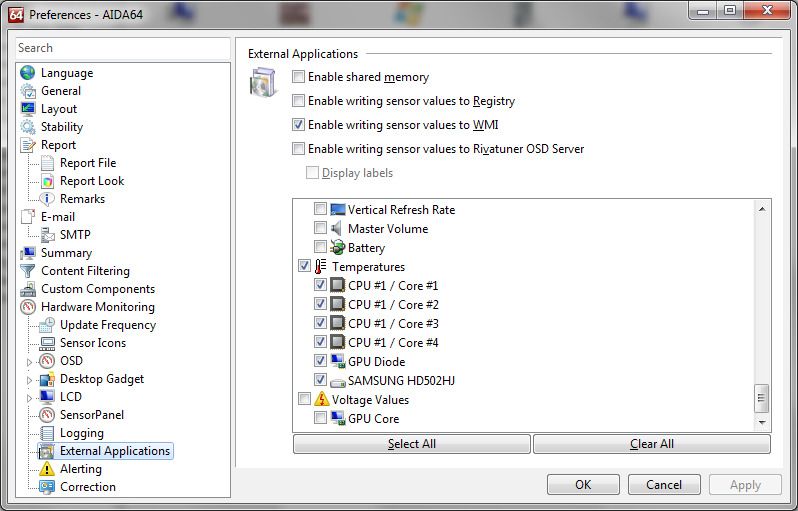
LEAKSHIELD                                                                 aquacomputer
Table of contents
1. Preface.........................................................................................4
2. Scope of delivery..........................................................................4
3. Safety precautions.........................................................................5
4. Requirements for the operation of LEAKSHIELD...............................5
5. Installation....................................................................................6
        5.1. Installation on ULTITUBE reservoirs (34137)....................................6
        5.2. Installation on aqualis or aquainlet series reservoirs (34144/34146). .6
6. Electrical connections....................................................................6
        6.1. Connector “USB”..........................................................................6
        6.2. Connector “signal”.......................................................................7
7. Operation on the device................................................................7
8. aquasuite software........................................................................8
        8.1. Installation of the aquasuite software...............................................8
        8.2. Basic operation............................................................................9
        8.3. Symbols in the headlines................................................................9
9. Overview pages (aquasuite).........................................................10
        9.1. Desktop mode............................................................................10
        9.2. Creating new overview pages and activating edit mode..................10
        9.3. Adding new elements..................................................................10
        9.4. Editing existing elements..............................................................11
        9.5. Values and names......................................................................11
        9.6. Detailed data elements................................................................11
        9.7. Log data chart............................................................................11
        9.8. User defined: Images, text, drawing elements.................................11
        9.9. Export and import of overview pages.............................................12
10. Data quick view and data log (aquasuite)...................................12
        10.1. Log settings..............................................................................13
        10.2. Analyze data............................................................................13
        10.3. Manual data export...................................................................14
        10.4. Automatic data export...............................................................14
11. Page “LEAKSHIELD”..................................................................15
        11.1. The settings wizard....................................................................16
        11.2. The "Test" action.......................................................................18
        11.3. The "Measure fill level" action.....................................................18
        11.4. The "Deaerate system" action......................................................19
        11.5. The "Refill system" action............................................................19
12. Sensor configuration.................................................................19
        12.1. Pressure...................................................................................20
        12.2. Fill level...................................................................................20
        12.3. Volume change........................................................................20
-2-                               Aqua Computer GmbH & Co. KG                                      © 2021
                                 Gelliehäuser Str. 1, 37130 Gleichen
aquacomputer                                                                         LEAKSHIELD
        12.4. Pressure change.......................................................................20
        12.5. Pump speed.............................................................................20
        12.6. Flow........................................................................................21
        12.7. Software sensors.......................................................................21
13. Display configuration................................................................22
        13.1. Display pages...........................................................................22
        13.2. Display settings.........................................................................23
14. RGBpx configuration.................................................................23
        14.1. Create and configure additional LED controllers...........................23
        14.2. Modify existing LED controllers...................................................24
        14.3. Modify LED assignments............................................................24
        14.4. Duplicate LED controllers...........................................................24
        14.5. Delete LED controllers...............................................................24
15. Alarm configuration..................................................................24
        15.1. Leakage warning and alarms.....................................................25
        15.2. Fill level warning and alarm.......................................................25
        15.3. System alarm............................................................................25
16. The Status page........................................................................25
17. Profiles.....................................................................................26
        17.1. Manual profile selection............................................................26
        17.2. Automatic profile selection.........................................................26
        17.3. Profile configuration..................................................................26
18. System settings .........................................................................27
        18.1. Device information....................................................................27
        18.2. Device settings..........................................................................27
        18.3. Time settings............................................................................27
        18.4. Standby behavior......................................................................27
        18.5. Firmware update and language selection (aquasuite only).............27
19. Playground (aquasuite)..............................................................28
        19.1. Virtual Software Sensors.............................................................28
        19.2. Global profiles.........................................................................28
        19.3. Hotkeys...................................................................................29
20. aquasuite web..........................................................................29
        20.1. Data export..............................................................................29
        20.2. Data access.............................................................................30
        20.3. Data import..............................................................................30
21. Basic settings (aquasuite)...........................................................30
        21.1. Language................................................................................30
        21.2. Reorder menu items..................................................................30
        21.3. Units.......................................................................................31
        21.4. Application start-up...................................................................31
        21.5. Service administration...............................................................31

© 2021                           Aqua Computer GmbH & Co. KG                                           -3-
                                Gelliehäuser Str. 1, 37130 Gleichen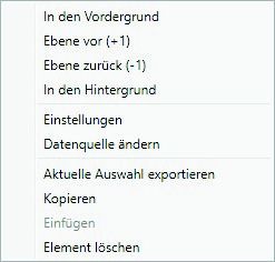
LEAKSHIELD                                                             aquacomputer
       21.6. Audio and video.......................................................................31
       21.7. Updates and update service.......................................................31
22. Technical details and care instructions........................................33
       22.1. Technical details.......................................................................33
       22.2. Care instructions.......................................................................33
       22.3. Waste disposal.........................................................................33
       22.4. Contact Aqua Computer............................................................33

1. Preface
LEAKSHIELD is a worldwide unique leakage protection system for liquid cooling
systems developed by Aqua Computer. It actively generates an optimally comput-
ed negative pressure in the cooling system which actively prevents the escape of
coolant in the event of a leak.

If a leak occurs, only air is sucked into the cooling system.

For this purpose, an integrated vacuum pump is activated in a fraction of a second
in the event of a leak and continues to maintain the required vacuum.

In addition, LEAKSHIELD uses a highly accurate sensor to detect and indicate even
minimal leaks. This allows countermeasures to be taken at a very early stage.

The system is also able to determine the fill level in the reservoir.

LEAKSHIELD was developed for the ULTITUBE reservoir series, but can also be
used with other reservoirs, e. g. from the aqualis, aquatube or aquainlet series, via
an adapter set (LEAKSHIELD UNIVERSAL). For further information, please refer to
the corresponding instructions for the adapter set.

LEAKSHIELD has an OLED display and a button control which allow the most im-
portant functions to be controlled directly on the device.

2. Scope of delivery
   ●   One LEAKSHIELD device
   ●   One internal USB cable (replacement part no. 53215)
   ●   34144 only: Two gaskets (replacement part number 94214)
   ●   34146 only: Two gaskets (replacement part number 94299)

3. Safety precautions
The following safety precautions have to be observed at all times:

-4-                            Aqua Computer GmbH & Co. KG                                    © 2021
                              Gelliehäuser Str. 1, 37130 Gleichen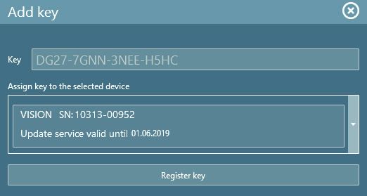
aquacomputer                                                        LEAKSHIELD
   ●   Read this manual thoroughly and entirely!
   ●   Save your data onto suitable media before working on your hardware!
   ●   This product is not designed for use in life support appliances, devices, or
       systems where malfunction of this product can reasonably be expected to re-
       sult in personal injury. Aqua Computer GmbH & Co. KG customers using or
       selling this product for use in such application do so at their own risk and
       agree to fully indemnify Aqua Computer GmbH & Co. KG for any damages
       resulting from such application!
   ●    Never touch the membrane on the bottom side of LEAKSHIELD. Damage to
       the membrane can cause moisture to enter LEAKSHIELD and subsequently
       cause the unit to fail. If you notice any damage to the membrane, contact
       the Aqua Computer Technical Support
   ●   Use only DP Ultra as coolant

4. Requirements for the operation of LEAKSHIELD
In order to operate LEAKSHIELD properly, there are some principles to be ob-
served when selecting the cooling system.

LEAKSHIELD can only be used if the maximum pump pressure
                                                       ressure in the system is less
than 450 mbar.
          mbar This is the case for almost all systems with one pump. For systems
with more than one pump, this must be checked accordingly, e. g. by measuring
the pressure.

The second prerequisite is that the tubing is suitable for the required vacuum.
                                                                        vacuum

As a broad rule, the outer diameter of PVC tubing should be at least 1.5 times the
inner diameter of soft tubing.

For PUR tubing, a factor of 1.2 is usually sufficient. Hardtubes are generally suit-
able. Without information on compatibility, we recommend testing at slightly in-
creased negative pressure and maximum water temperature before use.

The components of the water cooling system have to be suitable for the operation
with LEAKSHIELD as well and have to withstand the necessary negative pressure
permanently. For Aqua Computer products this applies without exceptions. For
products from other suppliers, you have to check this before starting operation!

It is also important that there is sufficient air volume in the reservoir.
                                                                reservoir For safe oper-
ation, there should be at least 100 ml of air in the reservoir.

To ensure safe operation, only coolants of the DP Ultra series are approved for
use. Even if many other coolants are certainly trouble-free, we cannot guarantee
the function with these coolants.
© 2021                      Aqua Computer GmbH & Co. KG                            -5-
                           Gelliehäuser Str. 1, 37130 Gleichen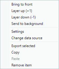
LEAKSHIELD                                                       aquacomputer
Especially coolants with particles are able to clog or even destroy the membrane
of LEAKSHIELD. Under no circumstances should coolants with flammable sub-   sub-
stances be used!

5. Installation
5.1. Installation on ULTITUBE reservoirs (34137)
Hold the glass tube of the reservoir and remove the top lid from the reservoir by
turning it anti-clockwise. Install LEAKSHIELD by screwing it onto the ULTITUBE. Af-
ter installation, the display can still be rotated to a desired position.

5.2. Installation on aqualis or aquainlet series reservoirs (34144/34146)
Attention: Drain all coolant from the reservoir before unscrewing the top lid!
Coolant will otherwise leak from both ends of the glass tube!
Remove the top lid from the reservoir by turning it anti-clockwise. For security rea-
sons, remove the glass tube and replace the gasket between reservoir base and
glass tube. Realign the glass tube with the base of the reservoir and screw LEAK-
SHIELD onto the reservoir using another new gasket. Make sure all components
are properly aligned and fasten LEAKSHIELD securely to the reservoir. After instal-
lation, the display can still be rotated to a desired position.

6. Electrical connections
ATTENTION: Completely turn off your power supply or disconnect the mains pow-
er cord from the wall outlet before connecting or disconnecting any cables to/from
the device!

6.1. Connector “USB”
This connector is used for USB communication with a PC. Connect to an internal
USB header of your motherboard. Take special care to make sure the pin align-
ment matches your motherboard!

ATTENTION: To be able to operate LEAKSHIELD even when the PC is in standby,
you must configure the USB port in the Bios settings in such a way that the power
supply remains activated. Alternatively, you can use external USB power supplies
for the power supply. For a transportation, you can also use a USB power bank

Pin assignment:   Pin 1   GND    (black), optional
                  Pin 2   GND    (black)
                  Pin 3   D+     (green)
                  Pin 4   D-     (white)
                  Pin 5   +5 V   (red)
-6-                         Aqua Computer GmbH & Co. KG                      © 2021
                           Gelliehäuser Str. 1, 37130 Gleichen
aquacomputer LEAKSHIELD
The corresponding connector on the motherboard is usually
a 9 pin connector with two independent USB ports. Both
rows of 4/5 pins can be used to connect an USB device.
The black wires (GND) are to be connected to the side of
the missing pin, see picture with colored pin assignment.
6.2. Connector “signal”
The header can be connected to the power switch header of the motherboard us-
ing an additional specialized cable (53216, not included in delivery).
Pin assignment: Pin 1: GND
Pin 2: not connected
Pin 3: open drain max 3.3 V / 5 mA
In the event of an alarm, this interface can be used to shut down the computer in
the same way as pressing the power button. A short or long press can be config-
ured.
7. Operation on the device
The most important functions of LEAKSHIELD can be controlled directly on the de-
vice. A button located at the right side of the LEAKSHIELD silicone illuminated ring
is used to control the menu.
By a short press on the button, it is possible to navigate directly through the display
pages.
If the button is pressed for longer than one second, the menu is displayed.
At this moment, "MENU" appears briefly in the display, followed by the menu
items.
By shortly pressing the key, you can now select between the following items:
SHIELD (mode selection)
Complete protection and detection of leakages. This function can only be used re-
liably after a configuration via the aquasuite!
MONITOR (mode selection)
The system is monitored for leaks by using a low negative pressure. There is no
protection against leakage in this mode.
RELEASE (mode selection)
© 2021 Aqua Computer GmbH & Co. KG -7-
Gelliehäuser Str. 1, 37130 GleichenLEAKSHIELD aquacomputer
The LEAKSHIELD system is switched off. The vacuum is automatically released, and
pressure equalization occurs automatically.
TESTER (Action)
In this action, a leak test of the cooling system is enabled. A configurable negative
pressure is generated as a test pressure and then the pressure loss is displayed.
FILL (Action)
This action makes it possible to suck coolant into the system. A vacuum of between
250 and 300 mbar is generated for this purpose.
During filling, the water pump must be switched off. Therefore, we recommend fill-
fill-
ing while the PC is on standby!
DEAERATION (action)
This action supports the venting of the system during filling by cyclically generating
and releasing negative pressure.
LEVEL SENSOR (action)
The measurement of the level in the reservoir is triggered by this action. This func-
tion can only be used appropriately after configuration via the aquasuite!
EXIT
Exit the menu.
The respective function is selected by pressing the key again for a longer than 1
second.
8. aquasuite software
The Windows software aquasuite is an extensive software suite and can be used
for configuration and monitoring. The software is not required for operation
though. All configuration parameters can be saved into the device's memory.
Please note: Depending on the type of product you are using, some features may
not be available for your device.
8.1. Installation of the aquasuite software
For configuration and monitoring of our products with USB interface, the aquasui-
te software is available for download from our website www.aqua-computer.de.
You will find the setup program in the support section of the website under Down-
loads/Software.
The setup program checks all connected USB devices for embedded update ser-
vice periods and offers various aquasuite versions depending on detected devices.
If no device with update service for the latest aquasuite version is found, a warning
-8- Aqua Computer GmbH & Co. KG © 2021
Gelliehäuser Str. 1, 37130 Gleichenaquacomputer LEAKSHIELD
is displayed and older aquasuite versions that do not require an update service
purchase can be selected for installation. For installation and update service vali-
dation, an internet connection is required.
The latest aquasuite version may also be installed if no suitable update service pe-
riod has been found in a device. Subsequently, update service may be purchased
or an existing key may be entered within the aquasuite. These functions can be ac-
cessed in the aquasuite/Updates tab.
8.2. Basic operation
The program window is divided into two main areas. On the left side, a list of
“overview pages”, data quick view, data logger, device pages, aquasuite web and
aquasuite configuration is displayed, the right side shows the details of the current-
ly selected list element. The list can be hidden or restored by clicking the arrow
symbol in the upper left corner.
List elements may be minimized or maximized for easier access by clicking the title
bar. The title bars may contain various symbols that will be explained in the follo-
wing chapter.
8.3. Symbols in the headlines
Click the plus symbol in the “Overview pages” headline to create a new
overview page.
Clicking the monitor symbol will toggle desktop mode for this overview
page. While desktop mode is active, the color of the symbol will change
to orange.
Overview page: Clicking the padlock symbol will unlock or lock this over-
view page for editing. Device: Device can not be used due to update ser-
vice problems, see “Updates and update service” for details.
Clicking the gear symbol will access the basic configuration page of the
selected list element.
In order to save all settings into a device, click the disk symbol in the
headline.
This symbol indicates that communication with this device is not possible
at the moment. Check USB connection and power supply of the device if
necessary.
9. Overview pages (aquasuite)
Current sensor readings and diagrams from all supported devices can be dis-
played in overview pages. For each device a pre-configured overview page is au-
tomatically generated the first time the device is connected to the PC. These pages
© 2021 Aqua Computer GmbH & Co. KG -9-
Gelliehäuser Str. 1, 37130 GleichenLEAKSHIELD aquacomputer
can be individually modified and new pages can be created. Within one overview
page, data from all connected devices can be accessed.
9.1. Desktop mode
Each overview page can be displayed directly on your desktop. You can enable
desktop mode for an overview page by clicking the monitor symbol in the list of
overview pages. Desktop mode can only be enabled for one overview page at a
time. With desktop mode enabled, elements of the overview page may cover pro-
gram symbols on your desktop, but mouse clicks are transmitted to underlying
desktop symbols.
If a overview page is unlocked for editing while desktop mode is active, the page
will be displayed in the aquasuite window for editing and the current desktop will
be displayed as background for your convenience.
9.2. Creating new overview pages and activating edit mode
In order to create a new overview page, click the plus symbol in the headline
“Overview pages”.
Existing overview pages can be unlocked for editing by clicking lock symbol in the
page listing.
9.3. Adding new elements
If the currently selected overview page is unlocked for editing, a plus symbol is dis-
played in the top right corner of the screen. Click the symbol to add a
new element to the page and select the desired element from the followi-
ng list. All available data is displayed in a tree diagram, click the arrow
symbols to access individual items.
Confirm your selection by clicking the check symbol in the bottom right corner.
The new element will be displayed in the upper left corner and the configuration
window is displayed. Configure the element as described in the next chapters.
- 10 - Aqua Computer GmbH & Co. KG © 2021
Gelliehäuser Str. 1, 37130 Gleichenaquacomputer LEAKSHIELD
9.4. Editing existing elements
If the currently selected overview page is unlocked for
editing, right-clicking an element will access a context
menu.
To access the settings of an element, select “Settings”
in the context menu or simply double click the element.
If you want to move an element, “drag” this element
while holding down the mouse button. Release the
mouse button when the element is at the desired positi-
on.
9.5. Values and names
If the currently selected overview page is unlocked for editing, right-click an ele-
ment and select “Settings”. You may also double click the element.
Font face, size and color as well as position, decimal places and unit can be confi-
gured for individual values.
9.6. Detailed data elements
If the currently selected overview page is unlocked for editing, right-click an ele-
ment and select “Settings”. You may also double click the element. Apart from po-
sition, size and color, the style of the element can be selected and configured. The
following styles are available:
● Headline only: Compact display as a headline.
● Text: Displays the numerical value in a box with a headline.
● Bar graph: Displays numerical value as well as bar graph.
● Chart: Displays the value in chronological sequence as a chart.
● Gauge: Displays the value as a analog gauge.
All display styles offer extensive configuration options, additionally statistical data
such as minimum, maximum and average can be displayed.
9.7. Log data chart
This element can be used to display charts on overview pages. The charts have to
be created using the data log functionality of the aquasuite before they become
available for overview pages. Please refer to the next chapter for details. Once a
chart has been configured, it can be selected from the “Chart selection” list on the
“Display” tab of the settings dialog.
9.8. User defined: Images, text, drawing elements
By using user defined controls, simple drawing elements such as circles, rectangles
and texts as well as images and more sophisticated elements can be added to an
overview page. To do so, add an “User defined” element to an overview page.
Switch to the “Display” tab in following dialog box, select the type of element to be
© 2021 Aqua Computer GmbH & Co. KG - 11 -
Gelliehäuser Str. 1, 37130 GleichenLEAKSHIELD aquacomputer
created from the drop down menu and confirm your selection by clicking the
“Load preset” button. Depending on the type of element, an additional dialog may
appear before the code (XAML, Extensible Application Markup Language) of the
new element is displayed in the lower part of the dialog window. You may want to
customize the code. By clocking the “Ok” Button, the new control is saved to the
overview page.
Step-by-step example to add an image: Select “Image” from the drop down menu
and click the “Load preset” button. Select an image file using the following file se-
lection dialog. The code is then displayed in the lower part of the dialog window
an can be modified. Save the new control by clicking the “Ok” button. The picture
will be displayed on the overview page.
More complex controls such as data bindings and animations are also available
but will require some programming experience for configuration.
9.9. Export and import of overview pages
Elements and complete overview pages can exported from the aquasuite and can
then be imported either on the same PC or on other PCs. For export as well as im-
port, the overview page must be in edit mode.
To export a complete page, right click a free spot of the page and select “Export
page” from the context menu. To export individual elements, select the element or
elements, perform a right click and select “Export selected” from the context menu.
For import, right click a free spot of the page and select “Import page” or “Import
items”from the context menu. Using “Import page”, the current page will be dele-
ted and only the imported page items will be displayed, using “Import items” will
add the items from file to the current page without altering the existing items. Du-
ring import, the elements will be assigned to devices using the following scheme:
If a device with identical serial number is found on the computer, no changes are
made.
If no device with identical serial number is found on the computer, the element will
be assigned to the first device found of identical type.
When importing complex pages with elements referring to more than one device, it
is recommended to edit the device assignment in the file using a text editor prior to
importing.
10. Data quick view and data log (aquasuite)
All data currently monitored by the aquasuite can be accessed in the “Data quick
view” section. This includes data from connected USB devices as well as hardware
data supplied by the Aqua Computer background service. Displayed data may be
filtered using the text box next to the magnifier icon, a chart shows the develop-
ment over a maximum of ten minutes. All data shown here is not stored per-
manently.
- 12 - Aqua Computer GmbH & Co. KG © 2021
Gelliehäuser Str. 1, 37130 Gleichenaquacomputer LEAKSHIELD
In contrast, the “Data log” may be used to selectively and permanently store data
from all connected Aqua Computer devices and hardware data supplied by the
background service. Logged data can then be analyzed by creating charts or be
exported to files. Data is only logged while the aquasuite software is being execu-
ted.
10.1. Log settings
The log settings can be accessed by clicking the “Log settings” element
below the “Data log” headline in the listing. To log data, create a new
log data set by clicking the plus symbol in the upper right corner of the
settings window. Enter name, time interval and configure automatic deletion of old
data to meet your requirements. You may then add the data sources to log by
clicking the plus symbol in the “Data sources” window section. You may add an
unlimited number of data sources to each log data set, the total number of log
data sets is also unlimited.
10.2. Analyze data
Logged data can be visually evaluated as charts. To do so, select “Analy-
ze data” below the “Data log” headline in the listing. The chart will initial-
ly be empty, directly below the chart are eight buttons to modify the chart.
In the lower section of the window, the chart data can be configured.
To add data to the chart, first select the “Data sources” tab in the chart configura-
tion and select a data set to be displayed. If no data sources are available, you
will have to configure the log settings as described in the chapter “Log settings” of
this manual. Select the time period to be displayed on the right side of the window
and add the data to the chart by clicking the “Add data to chart” button. Repeat
this procedure if you want to display more than one data set in the chart.
You may modify the chart using the “Chart setup” and “Data series setup” tabs.
Finally, you can use the “Chart manager” tab to save the current chart configurati-
on and to load or delete previously saved configurations. All saved chart configu-
rations will be available on overview pages for the “Log data chart” element.
The currently displayed chart can be edited by using the buttons directly below the
chart and may also be saved as an image file. The button corresponding to the
currently selected function is highlighted by an orange frame. Please refer to the
following list for details on each function:
To save the currently displayed chart as an image file, click the floppy
disk symbol and select a name and location in the following dialog.
This function can be used to add horizontal lines to the chart. While this
function is activated, simply click into the chart to add a line at the current
cursor position.
© 2021 Aqua Computer GmbH & Co. KG - 13 -
Gelliehäuser Str. 1, 37130 GleichenLEAKSHIELD aquacomputer
This function can be used to add vertical lines to the chart. While this
function is activated, simply click into the chart to add a line at the current
cursor position.
This function can be used to add annotations to the chart. While this
function is activated, simply click into the chart to add an annotation at
the current cursor position. By clicking into the text box, you may edit the
text. You may also drag the little circle beside the text box to move the connecting
line to the desired position. Use drag and drop to move existing annotations.
This function can be used to remove horizontal/vertical lines or annotati-
ons from the chart. While this function is activated, simply click the ele-
ment to be removed.
This function can be used to move the visible portion of the chart. Press
and hold the mouse button while moving the cursor in the chart to select
the position to be displayed, then release the button.
This function can be used to zoom in and out. Use the mouse wheel or
select the area to be displayed. You can reset the zoom settings by dou-
ble-clicking in the chart area.
This function can be used to reload and update the chart.
This function will completely remove the chart.
10.3. Manual data export
Saved data can be exported from the data log into a XML file. To do so, select
“Analyze data” below the “Data log” headline in the listing. Select the “Data
sources” tab in the chart configuration and select a data set to be exported. If no
data sources are available, you will have to configure the log settings as described
in the chapter “Log settings” of this manual. Select the time period to be exported
on the right side of the window and start the export process by clicking the “Export
data” button. Enter a file name and path in the following dialog window.
10.4. Automatic data export
The automatic data export feature can be used to save data from the
aquasuite into an XML file on the hard disk or in the RAM (“memory map-
ped file”) in a regular time interval. The automatic data export will always
overwrite the previously saved data, so the file always contains only the most re-
cent data set. Select “Automatic data export” below the “Data log” headline in the
listing to access the settings screen. Create a new export data set by clicking the
plus symbol in the upper right corner of the screen. Enter name, path and time in-
terval to meet your requirements. You may then add the data sources to log by
clicking the plus symbol in the “Data sources” window section. You may add an
- 14 - Aqua Computer GmbH & Co. KG © 2021
Gelliehäuser Str. 1, 37130 Gleichenaquacomputer LEAKSHIELD
unlimited number of data sources to each export data set, the total number of ex-
port data sets is also unlimited.
11. Page “LEAKSHIELD”
Click on the "LEAKSHIELD" device page below the "LEAKSHIELD" entry.
The most important LEAKSHIELD functions are visualized and triggered
on this page.
In the right view you see an overview page. In the upper area, the most important
information about LEAKSHIELD is displayed. This includes the current vacuum, the
required vacuum for protection against leakage, the status, the current fill level of
the reservoir and the current volume change in the system.
The "Mode" display informs you about the current operating mode of your LEAK-
SHIELD. By clicking on this area you can change the modes.
The following modes are available:
• SHIELD (Complete protection by negative pressure and leak detection)
• MONITOR (Low negative pressure, leak detection only)
• RELEASE (System is switched off, automatic pressure compensation)
Below follows the an area „Action“ where you can select important device func-
tions directly by clicking on one of the symbols.
The following actions are available:
• Test: Test the cooling system for leaks
• Measure fill level: Measure the level in the reservoir.
• Deaerate system: Supports the venting of the system during filling
• Refill system: Suck coolant into the system
Depending on the currently selected action, the further display of the lower area of
this page changes.
In SHIELD and MONITOR mode, the middle area shows a diagram with the cur-
rent negative pressure and information on the minimum necessary negative pres-
sure, the current setpoint and the maximum negative pressure.
Below this is a diagram showing the pump running time per day. This serves as a
simple indicator for minor leakages. Tight systems should have a pumping time of
less than 15 seconds per day on average.
© 2021 Aqua Computer GmbH & Co. KG - 15 -
Gelliehäuser Str. 1, 37130 GleichenLEAKSHIELD aquacomputer
Upon completion of an action, LEAKSHIELD automatically returns to the previously
selected mode.
When starting up, first call up the settings wizard. You activate this by clicking on
the gearwheel at the very top right in the title bar.
11.1. The settings wizard
After calling up the wizard, a selection first appears in which you can choose be-
tween the wizard for the basic setting and an editing of the current setting. For
commissioning, leave the first preselected option selected and use the right arrow
to call up the next dialog.
In the reservoir dialog, select the reservoir you are using.
LEAKSHIELD needs this information to be able to determine the fill level correctly
and e.g. to be able to calculate the volume change properly.
For Aqua Computer products, you can select the reservoir used directly from the
drop-down selection field. For other reservoirs, you can enter user-defined values
manually.
Settings for total volume, the remaining air volume at maximum fill level as well as
at minimum fill level have to be made.
In addition, there is the option to measure the fill level automatically on a regular
basis. If this action is activated, LEAKSHIELD will measure the level regularly when
changes are made to the system (e.g. opening the reservoir) and after certain
times.
Caution: During the fill level measurement, the vacuum is released for a short
time. At this time there is no protection against leakage!
Now switch to the Pump dialog by clicking on the arrow symbol.
The pump used is the most important information for the operation of LEAK-
SHIELD. The pump type and the speed of the pump are used to calculate the pres-
sure of the pump at the operating point and LEAKSHIELD can adjust the vacuum
to your system accordingly.
The aquasuite automatically searches for Aqua Computer pumps in your system in
the background. If connected pumps are found via USB or aquabus, the correct
pump is usually preselected.
- 16 - Aqua Computer GmbH & Co. KG © 2021
Gelliehäuser Str. 1, 37130 Gleichenaquacomputer LEAKSHIELD
For Aqua Computer pumps that are not found automatically, you can select the
installed pump directly in the drop-down selection.
Other pumps can be configured via the user-defined setting. In this case you need
information about the maximum pressure of the pump and the maximum speed.
In addition, the aquasuite tries to find a data source for the speed of the pump. If
there is no selection in the data source field or if the selection is wrong, you can
correct it manually.
The pump speed is important to automatically adjust the vacuum to the operating
point of the pump.
Now go to the "Flow" section.
A flow sensor is not mandatory for the correct function of LEAKSHIELD. However, it
helps to calculate the operating point more precisely and to be able to reduce the
vacuum further.
LEAKSHIELD automatically searches for Aqua Computer flow sensors. If sensors
are found, the most useful sensor is automatically selected.
You can also make a selection manually using the "+" button or perform a new
search for sensors using the "Search Flow Sensor" function.
The next page "Pressure" allows you to skip the previously calculated values. This
function is only useful for experts and is not recommended.
The selection "Use adaptive pressure" is preselected and lets LEAKSHIELD adap-
tively calculate the optimal values at any time. If this selection is deactivated,
LEAKSHIELD works with the maximum possible pressure for the selected pump as
the operating point.
By selecting "Time controlled generation of negative pressure" you can select two
times at which LEAKSHIELD will build up the negative pressure again. This allows
you to schedule the operating noise of LEAKSHIELD at a time that does not disturb
you.
After leaving this page, you will reach the "Standby" section.
When booting from standby, no data can be sent to LEAKSHIELD via USB yet.
Therefore LEAKSHIELD needs defaults for the operating point of the pump. You
can select this data via speed and flow defaults. In addition, current values can be
taken from the assigned data source. If you do not know the data, you should not
activate a reduction of the vacuum in standby in the following option
© 2021 Aqua Computer GmbH & Co. KG - 17 -
Gelliehäuser Str. 1, 37130 GleichenLEAKSHIELD aquacomputer
In the standby of the PC the negative pressure can be reduced significantly if the
pump is switched off with the PC. To enable this, you can activate the correspond-
ing function here. The negative pressure in this condition can also be selected.
Now switch to the LEAKSHIELD "Mode" page.
You can now select the operating mode of LEAKSHIELD. As a most common rule,
the "SHIELD" mode should be selected. If the vacuum of LEAKSHIELD is not suffi-
cient to protect your system (too strong pump, several pumps), you can use the
mode "MONITOR". This will be indicated by corresponding warnings in the upper
part of the page.
The "RELEASE" mode only leads to a pressure equalization to the environment.
You will then be taken to a "Summary" of the selected settings and can check them
once again. Possible notes and warnings are displayed at the top of the table.
To change settings once again, you can navigate through the pages by pressing
the arrow icons. The checkmark symbol on the Summary page transfers the set-
tings to your LEAKSHIELD. If you cancel the wizard by clicking the "X" icon (top
right), the previous settings will be saved.
11.2. The "Test" action
In the Test mode, the desired negative pressure is requested first. You can perform
a leak test with negative pressures between 80 and 450 mbar.
Then LEAKSHIELD starts to prepare the test and to create the negative pressure.
Once this process is complete, LEAKSHIELD will show you a graph of the pressure
change over time. You can use the "Reference" button to select the current pres-
sure as a reference. In addition, the data source of the diagram can be changed.
The absolute current negative pressure, the pressure difference to the reference
value and the current pressure change are available for selection.
With the mouse you can enlarge areas in the diagram.
By pressing the "Cancel" field, you leave the test mode again.
11.3. The "Measure fill level" action
If you activate the fill level measurement by clicking on the symbol "Measure fill
level", a bar graph appears in the lower area which shows you the progress of the
measurement.
To do this, LEAKSHIELD first releases the negative pressure and then generates a
low negative pressure of approx. 100 mbar. The result of the measurement is then
displayed.
- 18 - Aqua Computer GmbH & Co. KG © 2021
Gelliehäuser Str. 1, 37130 Gleichenaquacomputer LEAKSHIELD
Note: There is no sufficient leakage protection during the level measurement. If
you have reason to believe that your system is not completely tight, you should not
activate the level measurement!
11.4. The "Deaerate system" action
After activating the action "Deaerate system", two progress bars appear. The first
shows the progress of the current cycle, the second the overall progress.
During this action, negative pressure is cyclically built up and released again. This
removes trapped air in the system step by step through expansion and compres-
sion.
11.5. The "Refill system" action
fill--
During filling, the water pump must be switched off. Therefore, we recommend fill
ing by pressing the button on LEAKSHIELD and while the PC is on standby!
If the action "Refill system" is selected, LEAKSHIELD generates a negative pressure
between 250 and 300 mbar. Coolant can be sucked into the system by this.
Pressing the "Pause" button pauses the pumping action, but the vacuum is not re-
leased. This prevents coolant from flowing back into the container.
If the process is terminated by pressing the "Exit" button, LEAKSHIELD switches to
the previously selected mode.
12. Sensor configuration
Select “Sensors” from the device list below the “LEAKSHIELD” entry. In the
upper area of the window, the 18 usable sensors are displayed with the
actual measured value. In the lower area of the window, the configura-
tion of the selected sensor can be made.
There are local sensors, sensors with extended configuration and software sensors
in this selection.
The local sensors are measured values of the sensors of LEAKSHIELD. For these
sensors, only the name and log interval can be selected.
The sensors with extended configuration are sensors for which extended settings
can be made and which have influence on the operation of LEAKSHIELD. These
settings are also possible via the wizard.
© 2021 Aqua Computer GmbH & Co. KG - 19 -
Gelliehäuser Str. 1, 37130 GleichenLEAKSHIELD aquacomputer
The software sensors (sensor 1-12) on the other hand are placeholders for data to
be transferred from your PC to LEAKSHIELD via USB.
Here all data of the aquasuite (incl. hardware monitoring and other Aqua Com-
puter devices) are available. In addition, a scaling factor and an offset can be se-
lected for these sensors.
The data transmitted in this way can later be shown on the display of LEAKSHIELD,
for example, or serve as a data source for RGBpx effects.
Please note that this data is only available when the Aqua Computer background
service is running and a USB connection to LEAKSHIELD exists. During the boot
process, for example, this is not the case!
The most important sensor values of LEAKSHIELD:
12.1. Pressure
The first displayed sensor indicates the current negative pressure in mbar.
12.2. Fill level
The second displayed sensor indicates the current fill level of the reservoir in per-
cent.
In the configuration section you have the possibility to start the fill level measure-
ment and to adjust the settings given in the wizard for this section. You will find
more information about the details in chapter 11.1 (Reservoir).
We recommend to make the settings only through the wizard.
12.3. Volume change
The third displayed sensor provides information about the volume change in ml/h.
This value can give you information about smaller leakages. However, this value
also changes when the temperature of your system changes.
12.4. Pressure change
The fourth displayed sensor provides similar information as the volume change
value, but here the pressure change is given in mbar per minute.
12.5. Pump speed
The fifth displayed sensor shows the current pump speed (if available). This value is
transmitted via USB from the Aqua Computer background service to LEAKSHIELD.
You can customize the sensor name and log interval.
- 20 - Aqua Computer GmbH & Co. KG © 2021
Gelliehäuser Str. 1, 37130 Gleichenaquacomputer LEAKSHIELD
In the configuration you can also view the settings of the wizard for the "Pump"
area and change them directly. You can find more information about the details in
chapter 10.1 (Pump). However, we recommend to make the settings only using the
wizard.
12.6. Flow
The sixth sensor displayed is the flow measurement value of your system (if avail-
able). This value is transmitted via USB from the Aqua Computer background ser-
vice to LEAKSHIELD.
In the configuration, you also have direct access to the settings made in the wizard
in the "Flow" area. In addition, you can adjust the sensor name and the log inter-
val.
You can find more information about the details in chapter 11.1 (Flow). We rec-
ommend that you only make the settings using the wizard.
12.7. Software sensors
The last twelve sensors in the list are software sensors and can be used to transmit
sensor data that is not physically available to LEAKSHIELD from the computer by
USB connection.
Select the appropriate unit for each configured data source. For manipulation of
the displayed sensor value, a scale factor and an offset may be configured. Data
from third party software regularly requires the scale factor to be adjusted.
Transmission of sensor data via USB interface
During installation of the aquasuite, the background service “Aqua Computer Ser-
vice” is also installed. This service supplies various data from PC components and
imported data from aquasuite web, additionally sensor data provided by third par-
ty software can be accessed. In order to access third party software data, the third
party software has to be correctly installed, configured and running.
Currently, the “Aqua Computer Service” supports data transfer from “HWiNFO”
(REALiX, Freeware, www.hwinfo.com) and “AIDA64” (FinalWire Ltd., subject to li-
cense fees, www.aida64.com).
HWiNFO automatically exports all sensor values, the “Sensor Status” Window has
to be open.
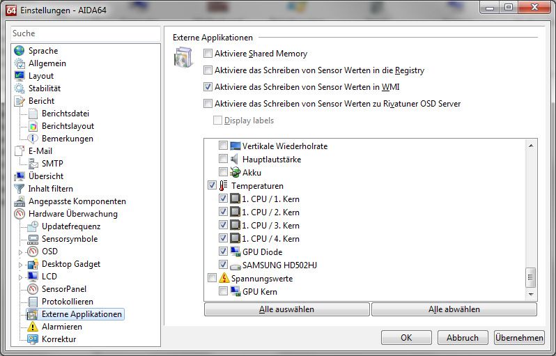
In the AIDA64 preferences menu, writing to WMI must be activated in the “external
applications” sub-menu:
© 2021 Aqua Computer GmbH & Co. KG - 21 -
Gelliehäuser Str. 1, 37130 GleichenLEAKSHIELD aquacomputer
By clicking the plus symbol labeled “Data source”, one of the provided sensors
can be assigned to the selected software sensor.
13. Display configuration
Click on the "Display" device page below the "LEAKSHIELD" entry. In the
upper part of the window the 10 available display pages of LEAKSHIELD
are shown. The content of these pages can be customized in each case.
13.1. Display pages
First select one of the 10 display pages for further configuration.
Then you can open the template selection by clicking on the enlarged preview of
the display.
A dialog opens allowing you to select a template from a gallery. Select a template
and you will be taken back to the configuration.
Depending on the selected template, one or more sensor values can be config-
ured.
If you want to display data from the hardware monitoring, for example, these must
be provided via a software sensor. Then the corresponding software sensor can
serve as data source for a template. In some cases, icons can also be selected for
the values or your own icons can be loaded.
In the template "Logo" you can display your own logo.
- 22 - Aqua Computer GmbH & Co. KG © 2021
Gelliehäuser Str. 1, 37130 Gleichenaquacomputer LEAKSHIELD
For each page you can select whether it should be displayed in standby of the PC
and whether it should be displayed in normal operation.
This allows a different selection of pages to be displayed for standby and opera-
tion.
13.2. Display settings
The brightness of the display as well as an automatic change of the display pages
can be configured.
The brightness can also be set for inactivity (no user interaction) and the display
can be switched off completely.
In addition, settings can be made here as to whether and after what time the dis-
play pages should change automatically.
The other options allow the display to be rotated by 180° and the display to be in-
verted.
Automatic inversion is activated at the factory. This significantly reduces the burn-in
of permanently activated pixels, which is typical for OLEDs.
As with all OLED displays, the brightness of active pixels decreases over time. For
homogeneous wear of all pixels, the display can be operated inverted half the
time. To compensate for existing wear, the inverted mode can also be activated
permanently.
The last option available here is the automatic shutdown of the display in standby.
This option significantly increases the life span of the display!
14. RGBpx configuration
Select “RGBpx” from the device list below the “LEAKSHIELD” entry. The
integrated RGBpx lighting (6 LEDs) can be configured.
14.1. Create and configure additional LED controllers
New LED controllers can be added by clicking the plus symbol. Alterna-
tively, use the right mouse button and select “New” from the context
menu. Select the desired effect from the superimposed list of available ef-
fects. The controller name can be altered from its default as well. Confirm you se-
lection by clicking the check symbol in the lower right corner.
The configuration of the newly added LED controller can be modified in the lower
area of the window. Most effects offer extensive customization options such as col-
© 2021 Aqua Computer GmbH & Co. KG - 23 -
Gelliehäuser Str. 1, 37130 GleichenLEAKSHIELD aquacomputer
or selection or speed adjustment. Additionally, many effects can be configured to
modify effect parameters depending on current sensor data.
In total, up to eight LED controllers (two for integrated lighting, six for external
components) can be configured.
14.2. Modify existing LED controllers
Existing LED controllers can be selected by clicking the corresponding col-
or bars, the configuration of the selected controller can then be modified
in the lower area of the window.
By clicking the gear symbol, the effect to be displayed can be changed and the
controller name can be altered. Confirm you selection by clicking the check sym-
bol in the lower right corner.
14.3. Modify LED assignments
Existing LED controllers can be moved by using “drag&drop”on the corre-
sponding color bars. The horizontal position of the color bar defines the
position of the effect on the connected LEDs. The vertical position deter-
mines the priority of the LED controllers, if multiple controllers are assigned to a
range of LEDs. Controllers positioned further up in the list have higher priority than
controllers further below.
The length of the bar (corresponding to the number of LEDs assigned) can be
changed by moving the right/left edge of the color bar.
14.4. Duplicate LED controllers
Select the LED controller(s) to be duplicated and click the duplicate sym-
bol to create new LED controllers using identical configurations. Alterna-
tively, use the right mouse button and select “Duplicate” from the context
menu.
In total, up to eight LED controllers (two for integrated lighting, six for external
components) can be configured.
14.5. Delete LED controllers
Select the LED controller(s) to be deleted and click the delete symbol to
delete the selected controllers. Alternatively, use the right mouse button
and select “Delete” from the context menu.
15. Alarm configuration
Select “Alarms” from the device list below the “LEAKSHIELD” entry.
- 24 - Aqua Computer GmbH & Co. KG © 2021
Gelliehäuser Str. 1, 37130 Gleichenaquacomputer LEAKSHIELD
15.1. Leakage warning and alarms
In the Leakage alarms section, one warning and two leakage alarms can be con-
figured. The threshold for the warning can be set via a slider depending on the
volume change. In addition, it is possible to select whether an acoustic alarm is to
be emitted in the event of a warning.
For two further alarms for smaller and larger leakages, the action can also be se-
lected here. These alarms are triggered by LEAKSHIELD with a predefined algo-
rithm and cannot be configured further.
The leakage alarms are always visualized acoustically and visually.
An action is also available for each warning and alarm. After pressing the "Edit ac-
tion" button, you can define a key sequence or an action of the power button via
the signal output within a dialog.
This enables the emergency shutdown of the computer when connecting the "sig-
nal" connector to the power button connector of the mainboard using a proper
connection cable (article 53216). Connect the alarm cable to the mainboard.
Then check the correct function by provoking an alarm. During the emergency
shutdown, data may be lost because the operating system and opened programs
are not closed properly!
15.2. Fill level warning and alarm
A warning and an alarm are available for the filling level. Both thresholds can be
set freely and an acoustic alarm can be activated for the warning.
As already described for the leakage alarms, the corresponding actions are also
available here.
The alarm is always visualized acoustically and optically.
15.3. System alarm
The system alarm is triggered in case of errors at LEAKSHIELD or the power supply.
Only the action in case of an alarm can be selected.
System alarms are always evaluated and visualized acoustically and optically.
16. The Status page
Click on the "Status" device page below the "LEAKSHIELD" entry.
© 2021 Aqua Computer GmbH & Co. KG - 25 -
Gelliehäuser Str. 1, 37130 GleichenLEAKSHIELD aquacomputer
On the Status page, all current operating data of LEAKSHIELD are visualized. For
this purpose, the status, the current negative pressure, the volume change in ml/h
and the pressure change in mbar per minute are displayed as values in the upper
area.
By clicking on one of the radio buttons, the corresponding value can be displayed
in a diagram below in the change over time.
The size of the diagram can be changed by using the dividing line below the dia-
gram.
In the middle of the page a symbolic illustration of LEAKSHIELD is shown. This
shows the components of the system, such as the vacuum pump, valves, etc., rep-
resented by symbols.
Currently active components are displayed in green. All important measured val-
ues are shown in the schematic.
In the lower part of the page, the current events are displayed in a list together
with the time and further details. In case of malfunctions, this list can be exported
and sent to Aqua Computer for further analysis.
17. Profiles
Select “Profiles” from the device list below the “LEAKSHIELD” entry.
The profile management can be used to to save four configurations as
profiles and activate them manually or automatically. Profile manage-
ment is a software feature of the aquasuite and requires a USB connection to the
LEAKSHIELD.
17.1. Manual profile selection
Select the profile to be activated by clicking the corresponding button.
17.2. Automatic profile selection
Profiles can be activated automatically using the global profiles feature of the
aquasuite, see chapter 14.2. for details.
17.3. Profile configuration
All configuration changes are automatically stored in the currently active profile.
The current configuration can also be stored in any other profile by clicking the
corresponding button.
- 26 - Aqua Computer GmbH & Co. KG © 2021
Gelliehäuser Str. 1, 37130 GleichenYou can also read